NISSAN TEANA 2003 Service Manual
TEANA 2003
NISSAN
NISSAN
https://www.carmanualsonline.info/img/5/57392/w960_57392-0.png
NISSAN TEANA 2003 Service Manual
Trending: bolt pattern, timing chain installation, warning, differential, keyless entry, start stop button, temperature
Page 2781 of 3502
![NISSAN TEANA 2003 Service Manual ACTIVE AFS
LT-93
C
D
E
F
G
H
I
J
L
MA
B
LT
DTC B2516 [SHIFT POS SIG (P, R)]BKS002FF
1. CHECK SIFT SIGNAL
1. Select “ADAPTIVE LIGHT” on CONSULT-II. Select “DATA
MONITOR” on “SELECT DIAG MOD NISSAN TEANA 2003 Service Manual ACTIVE AFS
LT-93
C
D
E
F
G
H
I
J
L
MA
B
LT
DTC B2516 [SHIFT POS SIG (P, R)]BKS002FF
1. CHECK SIFT SIGNAL
1. Select “ADAPTIVE LIGHT” on CONSULT-II. Select “DATA
MONITOR” on “SELECT DIAG MOD](/img/5/57392/w960_57392-2780.png)
ACTIVE AFS
LT-93
C
D
E
F
G
H
I
J
L
MA
B
LT
DTC B2516 [SHIFT POS SIG (P, R)]BKS002FF
1. CHECK SIFT SIGNAL
1. Select “ADAPTIVE LIGHT” on CONSULT-II. Select “DATA
MONITOR” on “SELECT DIAG MODE” screen.
2. When select lever is operated, check indication of the following
item.
OK or NG
OK >> INSPECTION END.
NG >> Check parking/neutral position (PNP) switch. Refer to
AT- 1 6 6 , "
PNP SWITCH" (with A/T) or CVT-62, "DTC
P0705 PARK/NEUTRAL POSITION SWITCH" (with CVT). If above system is normal, replace
AFS control unit. Refer to LT- 9 4 , "
Removal and Installation of AFS Control Unit" .
DTC B2517 [VEHICLE SPEED SIG]BKS002FG
1. CHECK VEHICLE SPEED SIGNAL
1. Select “ADAPTIVE LIGHT” on CONSULT-II. Select “DATA
MONITOR” on “SELECT DIAG MODE” screen.
2. When vehicle is moving, check the value in “VHCL SPD”.
Is the value in speedometer almost same as that in the monitor?
YES >> INSPECTION END.
NO >> Check METER & A/C AMP self-diagnosis result. Refer
to DI-29, "
SELF-DIAGNOSTIC RESULTS" . If above
system is normal, replace AFS control unit.
TEST ITEM Operation condition Reference value
SLCT LVR POSI Depending on select lever position P−1
PKIB8782E
PKIB8782E
Page 2782 of 3502
LT-94
ACTIVE AFS
Aiming AdjustmentBKS002FH
Refer to LT- 3 3 , "Aiming Adjustment" .
Bulb ReplacementBKS002FI
Refer to LT- 3 5 , "BENDING LAMP" .
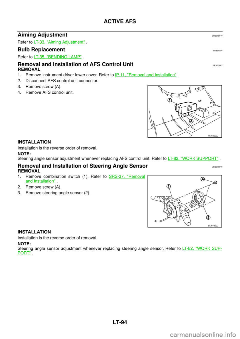
Removal and Installation of AFS Control UnitBKS002FJ
REMOVAL
1. Remove instrument driver lower cover. Refer to IP-11, "Removal and Installation" .
2. Disconnect AFS control unit connector.
3. Remove screw (A).
4. Remove AFS control unit.
INSTALLATION
Installation is the reverse order of removal.
NOTE:
Steering angle sensor adjustment whenever replacing AFS control unit. Refer to LT- 8 2 , "
WORK SUPPORT" .
Removal and Installation of Steering Angle SensorBKS002FK
REMOVAL
1. Remove combination switch (1). Refer to SRS-37, "Removal
and Installation" .
2. Remove screw (A).
3. Remove steering angle sensor (2).
INSTALLATION
Installation is the reverse order of removal.
NOTE:
Steering angle sensor adjustment whenever replacing steering angle sensor. Refer to LT- 8 2 , "
WORK SUP-
PORT" .
PKIC9222J
SKIB7829J
Page 2783 of 3502
HEADLAMP AIMING CONTROL (AUTO)
LT-95
C
D
E
F
G
H
I
J
L
MA
B
LT
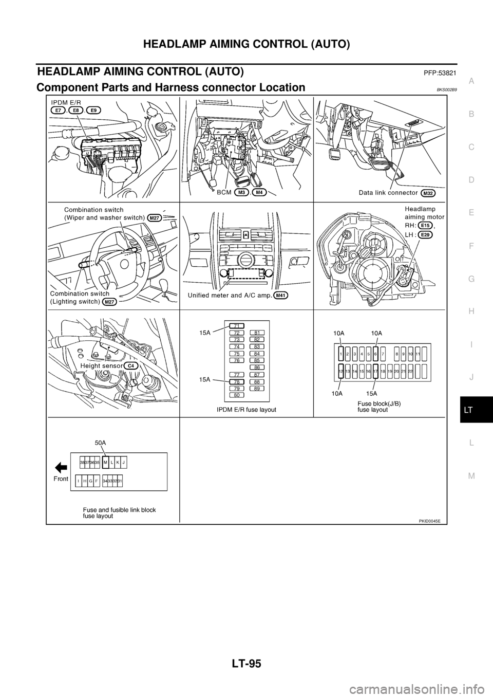
HEADLAMP AIMING CONTROL (AUTO)PFP:53821
Component Parts and Harness connector LocationBKS002B9
PKID0045E
Page 2784 of 3502

LT-96
HEADLAMP AIMING CONTROL (AUTO)
System DescriptionBKS002BA
The height sensor is located on the right side of the rear suspension member. With the lighting switch in the
1ST or 2ND position, the height sensor detects vehicle height change by sensing the displacement of the sus-
pension arm. And the height sensor transmits a corresponding signal to the headlamp aiming motors. The sig-
nal drives the headlamp aiming motors, which adjusts the low beam reflector of each headlamp to an angle
appropriate for the vehicle height.
The aiming motor drive signal level retains when the following conditions are not met.
�When the stopped vehicle changes the height and keeps it for more than 10 seconds, the height sensor
outputs a aiming motor drive signal. And height sensor keeps signal voltage to headlamp aiming motor.
Upon reception of the aiming motor drive signal, both headlamp aiming motors cause the low beam reflec-
tors to move to the position commanded by the signal.
�When the vehicle is running (excluded when accelerating/decelerating), the height sensor transmits aim-
ing motor drive signal to headlamp aiming motors at the predetermined intervals. The voltage level of
every signal input is maintained unchanged until the next signal is input.
Upon reception of the aiming motor drive signal, both headlamp aiming motors cause the low beam reflec-
tors to move to the position commanded by the signal.
�When the vehicle is accelerating or decelerating, the height sensor keeps the same aiming motor drive
signal voltage level rather than changing it, so that the low beam reflectors of both headlamps do not
operate.
When the lighting switch is turned OFF position, the height sensor retains the aiming motor drive signal level
at that moment and stops transmitting the signal.
OUTLINE
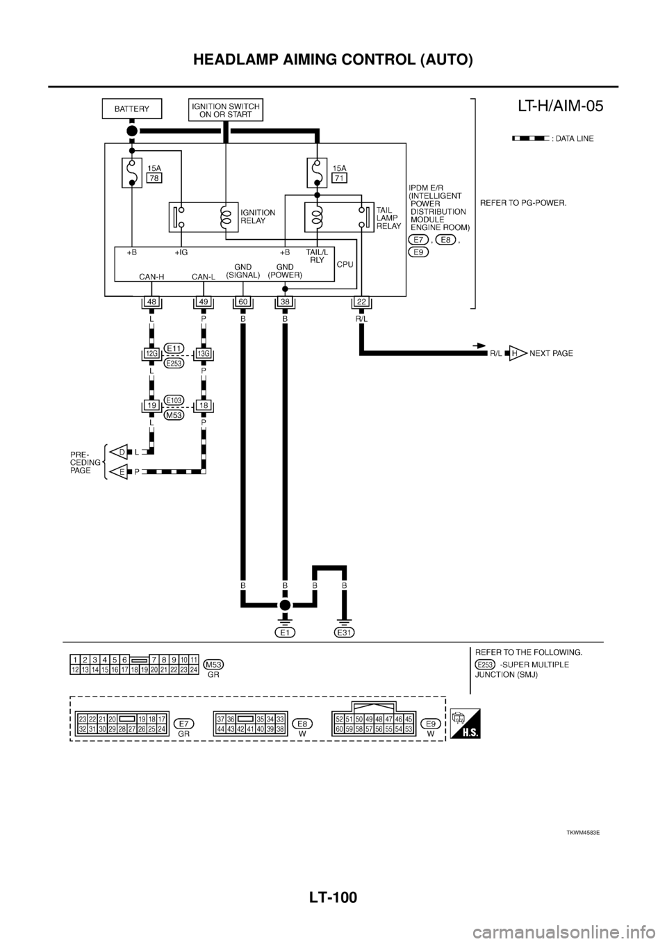
Power is supplied at all times
�to ignition relay [located in IPDM E/R (Intelligent Power Distribution Module Engine Room)], from battery
direct,
�through 15A fuse (No. 71, located in IPDM E/R)
�to tail lamp relay (located in IPDM E/R) and
�to CPU (central processing unit) in IPDM E/R,
�through 15A fuse (No. 78, located in IPDM E/R)
�to CPU in IPDM E/R,
�through 50A fusible link (letter M, located in fuse and fusible link block)
�to BCM terminal 55,
�through 15A fuse [No. 17, located in fuse block (J/B)]
�to BCM terminal 42.
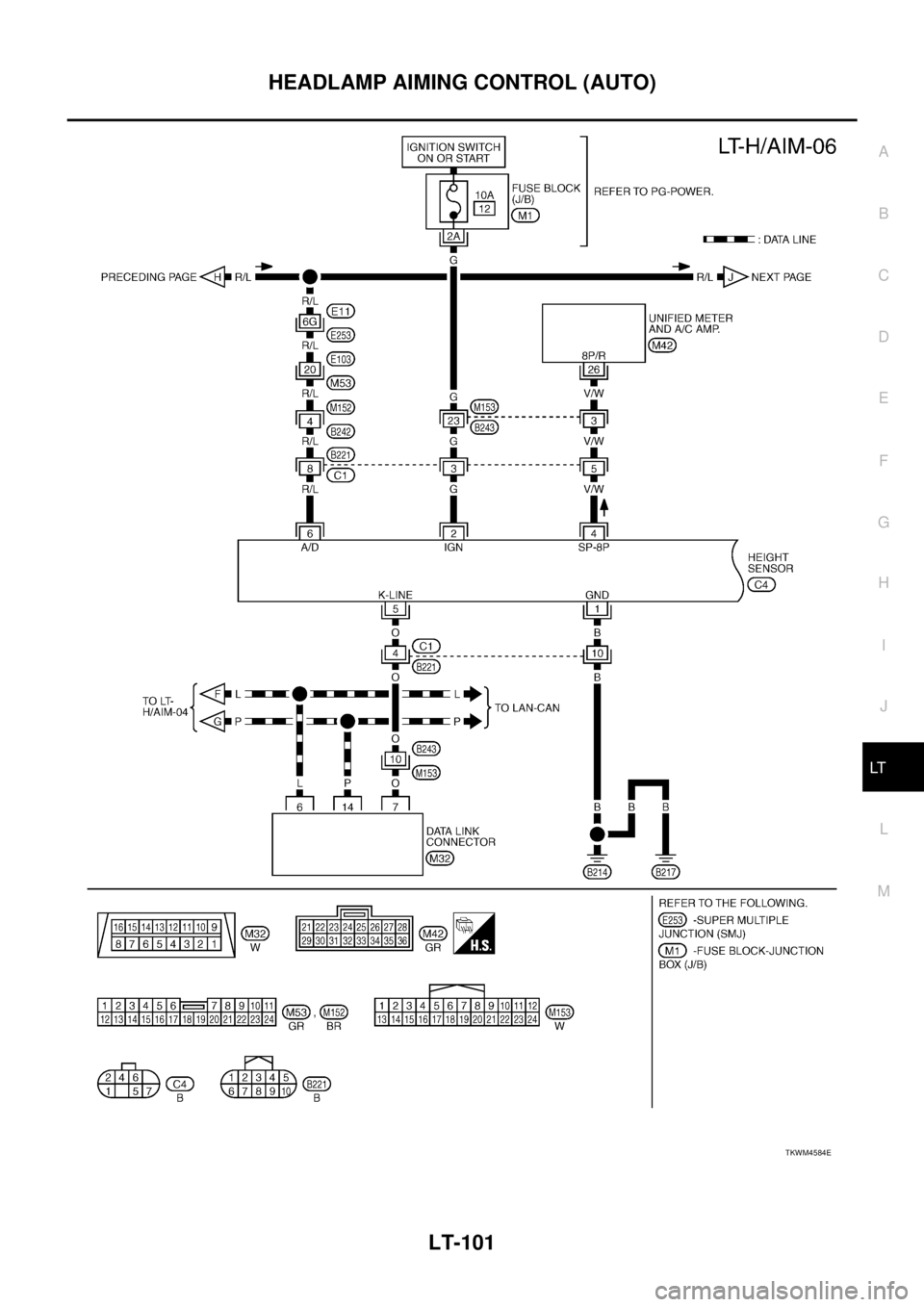
With the ignition switch in the ON or START position, power is supplied
�to ignition relay (located in IPDM E/R),
�through 10A fuse [No. 1, located in fuse block (J/B)]
�to BCM terminal 38,
�through 10A fuse [No. 12, located in fuse block (J/B)]
�to height sensor terminal 2.
With the ignition switch in ACC or ON position, power is supplied
�through 10A fuse [No. 6, located in fuse block (J/B)]
�to BCM terminal 11.
Ground is supplied
�to BCM terminal 52
�through grounds M71 and M72,
�to IPDM E/R terminals 38 and 60
�through grounds E1 and E31,
�to height sensor terminal 1
�through grounds B214 and B217.
Page 2785 of 3502

HEADLAMP AIMING CONTROL (AUTO)
LT-97
C
D
E
F
G
H
I
J
L
MA
B
LT
HEADLAMP AUTO AIMING CONTROL OPERATION
The height sensor is located on the right side of the rear suspension member and detects vehicle height
change by sensing the displacement of the suspension arm.
When the lighting switch is turned to the 1ST or 2ND position, power is supplied
�through IPDM E/R terminal 22
�to height sensor terminal 6 and
�to front combination lamp RH and LH terminals 3.
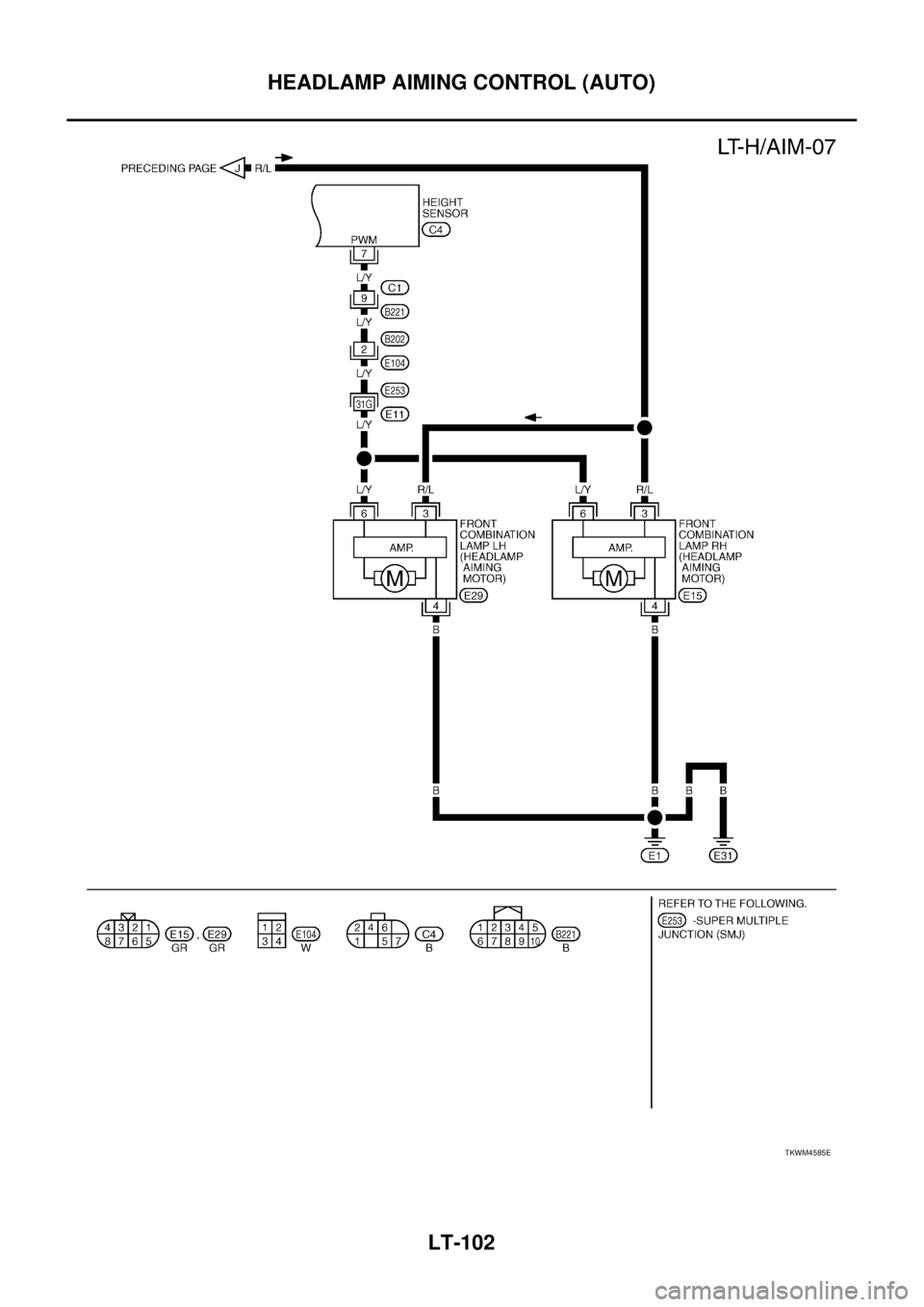
At the same time, the vehicle height signal (voltage signal that corresponds to the vehicle height) is applied
�through height sensor terminal 7
�to front combination lamp RH and LH terminals 6.
Ground is supplied
�to front combination lamp RH and LH terminals 4
�through grounds E1 and E31.
CAN Communication System DescriptionBKS0041M
CAN (Controller Area Network) is a serial communication line for real time application. It is an on-vehicle mul-
tiplex communication line with high data communication speed and excellent error detection ability. Many elec-
tronic control units are equipped onto a vehicle, and each control unit shares information and links with other
control units during operation (not independent). In CAN communication, control units are connected with 2
communication lines (CAN H line, CAN L line) allowing a high rate of information transmission with less wiring.
Each control unit transmits/receives data but selectively reads required data only.
CAN Communication UnitBKS0041N
Refer to LAN-49, "CAN System Specification Chart" .
Page 2786 of 3502
LT-98
HEADLAMP AIMING CONTROL (AUTO)
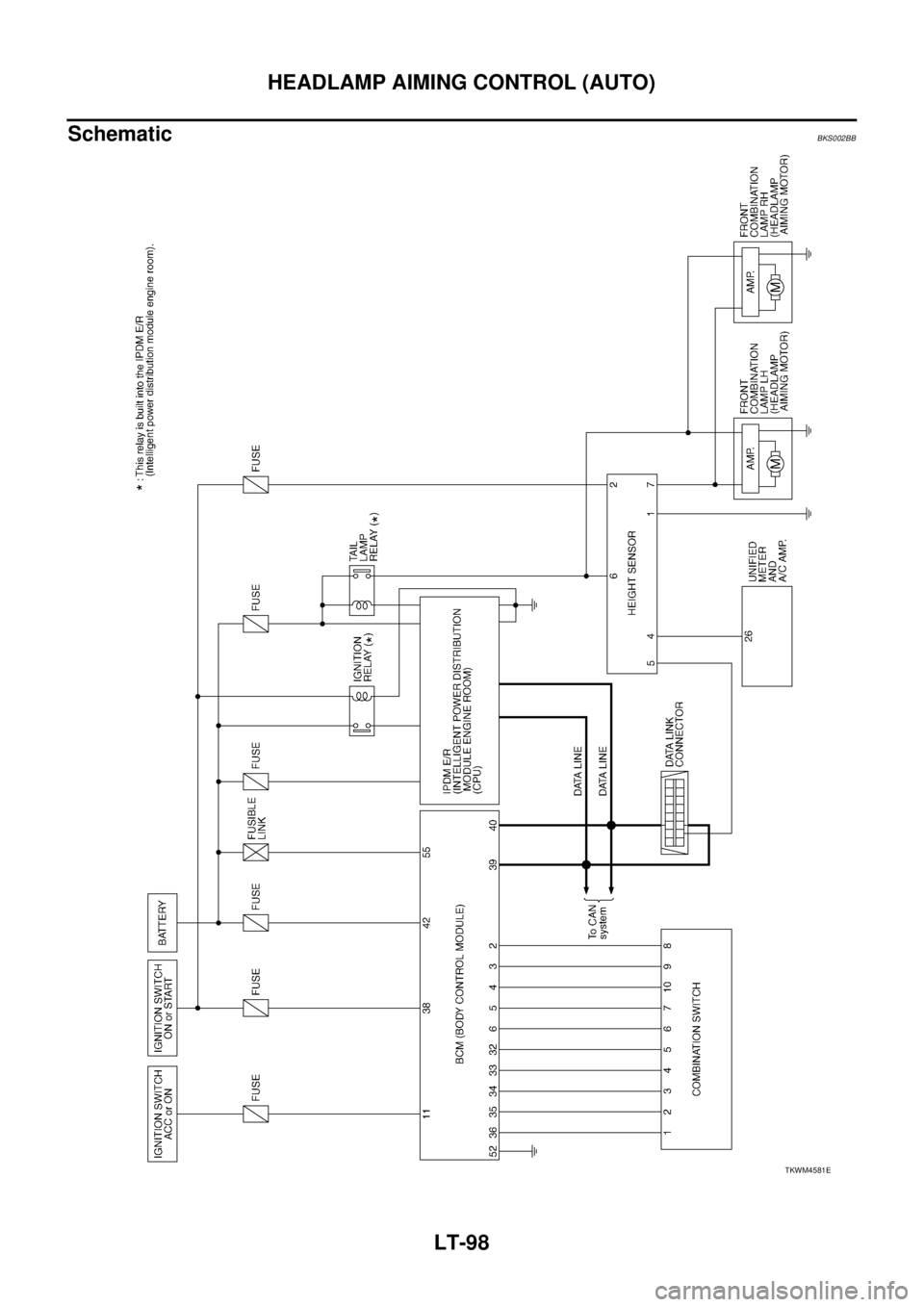
SchematicBKS002BB
TKWM4581E
Page 2787 of 3502
HEADLAMP AIMING CONTROL (AUTO)
LT-99
C
D
E
F
G
H
I
J
L
MA
B
LT
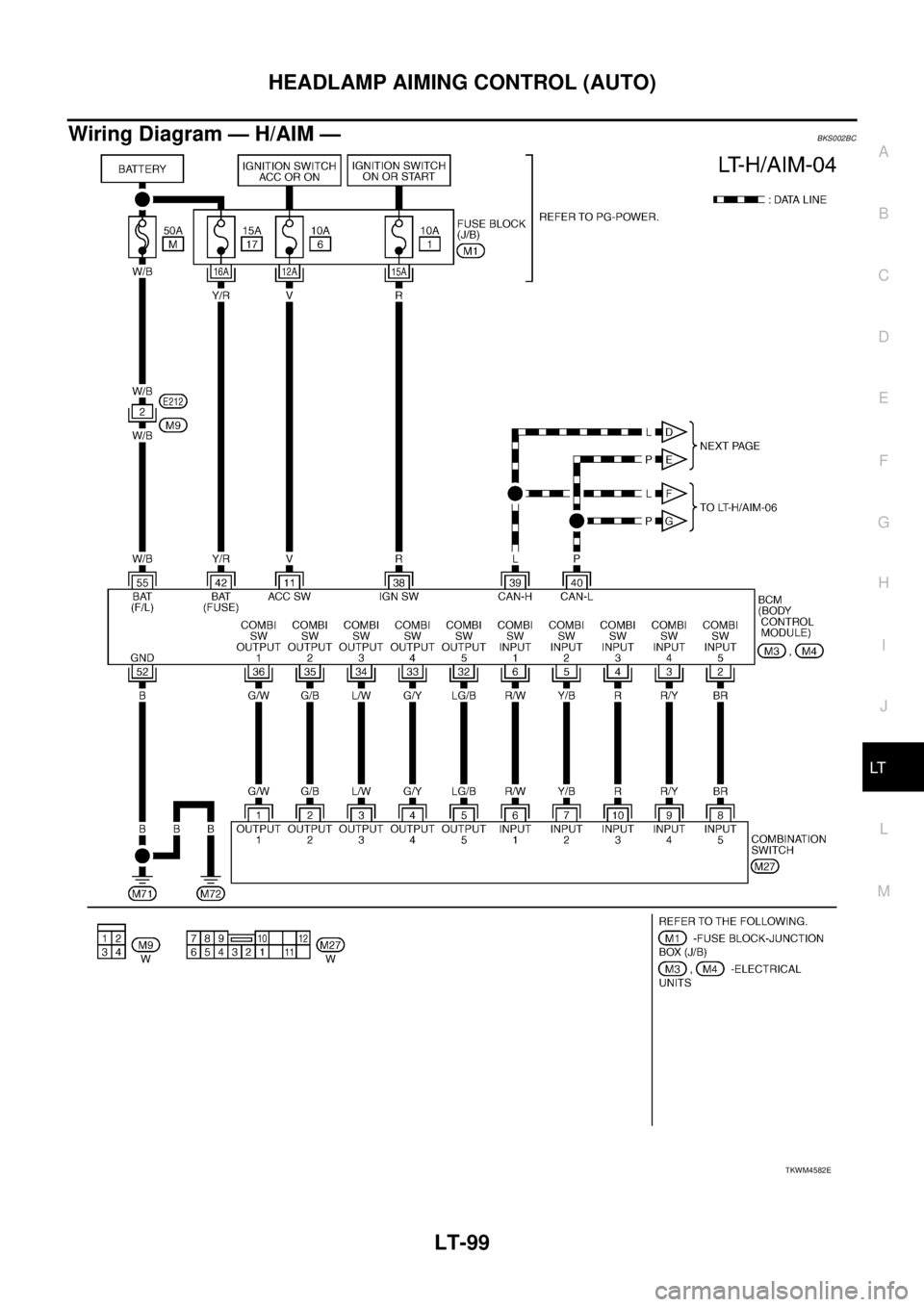
Wiring Diagram — H/AIM —BKS002BC
TKWM4582E
Page 2788 of 3502
LT-100
HEADLAMP AIMING CONTROL (AUTO)
TKWM4583E
Page 2789 of 3502
HEADLAMP AIMING CONTROL (AUTO)
LT-101
C
D
E
F
G
H
I
J
L
MA
B
LT
TKWM4584E
Page 2790 of 3502
LT-102
HEADLAMP AIMING CONTROL (AUTO)
TKWM4585E
Trending: tires, weight, low beam, ECO mode, height, navigation system, air conditioning
![NISSAN TEANA 2003 Service Manual ACTIVE AFS
LT-93
C
D
E
F
G
H
I
J
L
MA
B
LT
DTC B2516 [SHIFT POS SIG (P, R)]BKS002FF
1. CHECK SIFT SIGNAL
1. Select “ADAPTIVE LIGHT” on CONSULT-II. Select “DATA
MONITOR” on “SELECT DIAG MOD NISSAN TEANA 2003 Service Manual ACTIVE AFS
LT-93
C
D
E
F
G
H
I
J
L
MA
B
LT
DTC B2516 [SHIFT POS SIG (P, R)]BKS002FF
1. CHECK SIFT SIGNAL
1. Select “ADAPTIVE LIGHT” on CONSULT-II. Select “DATA
MONITOR” on “SELECT DIAG MOD](/img/5/57392/w960_57392-2780.png)
