fuel consumption NISSAN TEANA 2008 User Guide
[x] Cancel search | Manufacturer: NISSAN, Model Year: 2008, Model line: TEANA, Model: NISSAN TEANA 2008Pages: 5121, PDF Size: 69.03 MB
Page 1863 of 5121
![NISSAN TEANA 2008 User Guide EC-402
< SYMPTOM DIAGNOSIS >[VQ25DE, VQ35DE]
ENGINE CONTROL SYSTEM SYMPTOMS
SYMPTOM
Reference
page
HARD/NO START/RESTART (EXCP. HA)
ENGINE STALL
HESITATION/SURGING/FLAT SPOT
SPARK KNOCK/DETONATION
LA](/img/5/57391/w960_57391-1862.png "NISSAN TEANA 2008 User Guide EC-402
< SYMPTOM DIAGNOSIS >[VQ25DE, VQ35DE]
ENGINE CONTROL SYSTEM SYMPTOMS
SYMPTOM
Reference
page
HARD/NO START/RESTART (EXCP. HA)
ENGINE STALL
HESITATION/SURGING/FLAT SPOT
SPARK KNOCK/DETONATION
LA")
EC-402
< SYMPTOM DIAGNOSIS >[VQ25DE, VQ35DE]
ENGINE CONTROL SYSTEM SYMPTOMS
SYMPTOM
Reference
page
HARD/NO START/RESTART (EXCP. HA)
ENGINE STALL
HESITATION/SURGING/FLAT SPOT
SPARK KNOCK/DETONATION
LACK OF POWER/POOR ACCELERATION
HIGH IDLE/LOW IDLE
ROUGH IDLE/HUNTING
IDLING VIBRATION
SLOW/NO RETURN TO IDLE
OVERHEATS/WATER TEMPERATURE HIGH
EXCESSIVE FUEL CONSUMPTION
EXCESSIVE OIL CONSUMPTION
BATTERY DEAD (UNDER CHARGE)
Warranty symptom code AA AB AC AD AE AF AG AH AJ AK AL AM HA
Fuel Fuel tank
5
5FL-9
Fuel piping 5 5 5 5 5 5FL-4
Va p o r l o c k—
Valve deposit
5 555 55 5—
Poor fuel (Heavy weight gasoline,
Low octane)—
Air Air duct
55555 5EM-26
Air cleanerEM-26
Air leakage from air duct
(Mass air flow sensor — electric
throttle control actuator)
5555EM-26
Electric throttle control actuatorEM-29
Air leakage from intake manifold/
Collector/GasketEM-29,
EM-32
Cranking Battery
111111
11PG-109
Generator circuitCHG-20
Starter circuit 3STR-5,
STR-6
Signal plate 6EM-104
PNP signal 4TM-48,
TM-214
Engine Cylinder head
55555 55 5EM-97
Cylinder head gasket 4 3
Cylinder block
66666 66 64
EM-110
Piston
Piston ring
Connecting rod
Bearing
Crankshaft
Page 1864 of 5121
![NISSAN TEANA 2008 User Guide ENGINE CONTROL SYSTEM SYMPTOMS
EC-403
< SYMPTOM DIAGNOSIS >[VQ25DE, VQ35DE]
C
D
E
F
G
H
I
J
K
L
MA
EC
N
P O
1 - 6: The numbers refer to the order of inspection.Va l v e
mecha-
nismTiming chain
55555](/img/5/57391/w960_57391-1863.png "NISSAN TEANA 2008 User Guide ENGINE CONTROL SYSTEM SYMPTOMS
EC-403
< SYMPTOM DIAGNOSIS >[VQ25DE, VQ35DE]
C
D
E
F
G
H
I
J
K
L
MA
EC
N
P O
1 - 6: The numbers refer to the order of inspection.Va l v e
mecha-
nismTiming chain
55555")
ENGINE CONTROL SYSTEM SYMPTOMS
EC-403
< SYMPTOM DIAGNOSIS >[VQ25DE, VQ35DE]
C
D
E
F
G
H
I
J
K
L
MA
EC
N
P O
1 - 6: The numbers refer to the order of inspection.Va l v e
mecha-
nismTiming chain
55555 55 5EM-65
CamshaftEM-84
Intake valve timing controlEM-65
Intake valve
3EM-97
Exhaust valve
Exhaust Exhaust manifold/Tube/Muffler/
Gasket
55555 55 5EM-34
, EX-
4Three way catalyst
Lubrica-
tionOil pan/Oil strainer/Oil pump/Oil
filter/Oil gallery/Oil cooler
55555 55 5LU-7
, LU-
10, LU-11,
LU-13
Oil level (Low)/Filthy oilLU-7
Cooling
Radiator/Hose/Radiator filler cap
55555 55 45CO-12,
CO-12
Thermostat 5CO-23
Water pumpCO-18
Water galleryCO-2
Cooling fan
5CO-16
Coolant level (Low)/Contaminat-
ed coolantCO-8
NVIS (NISSAN Vehicle Immobilizer System —
NATS)11SEC-14
SYMPTOM
Reference
page
HARD/NO START/RESTART (EXCP. HA)
ENGINE STALL
HESITATION/SURGING/FLAT SPOT
SPARK KNOCK/DETONATION
LACK OF POWER/POOR ACCELERATION
HIGH IDLE/LOW IDLE
ROUGH IDLE/HUNTING
IDLING VIBRATION
SLOW/NO RETURN TO IDLE
OVERHEATS/WATER TEMPERATURE HIGH
EXCESSIVE FUEL CONSUMPTION
EXCESSIVE OIL CONSUMPTION
BATTERY DEAD (UNDER CHARGE)
Warranty symptom code AA AB AC AD AE AF AG AH AJ AK AL AM HA
Page 3090 of 5121
![NISSAN TEANA 2008 User Guide LAN
CAN COMMUNICATION SYSTEM
LAN-23
< FUNCTION DIAGNOSIS >[CAN]
C
D
E
F
G
H
I
J
K
L B A
O
P N
NOTE:
Refer to LAN-19, "
Abbreviation List" for the abbreviations of the connecting units.
T: Transmit R:](/img/5/57391/w960_57391-3089.png "NISSAN TEANA 2008 User Guide LAN
CAN COMMUNICATION SYSTEM
LAN-23
< FUNCTION DIAGNOSIS >[CAN]
C
D
E
F
G
H
I
J
K
L B A
O
P N
NOTE:
Refer to LAN-19, \"
Abbreviation List\" for the abbreviations of the connecting units.
T: Transmit R:")
LAN
CAN COMMUNICATION SYSTEM
LAN-23
< FUNCTION DIAGNOSIS >[CAN]
C
D
E
F
G
H
I
J
K
L B A
O
P N
NOTE:
Refer to LAN-19, "
Abbreviation List" for the abbreviations of the connecting units.
T: Transmit R: Receive
Signal name/Connecting unitECM
ADP
AV
HVAC
M&A
STRG
BCM
ABS
TCM
IPDM-E
A/C compressor request signal TR
Accelerator pedal position signal T R R
ASCD CRUISE indicator signal T R
ASCD operation signal T R
ASCD SET indicator signal T R
Closed throttle position signal T R
Cooling fan speed request signal TR
Engine and CVT integrated control signalTR
RT
Engine coolant temperature signal T R
Engine speed signal T R R R
Engine status signal T R R
Fuel consumption monitor signal T R
Malfunctioning indicator lamp signal T R
Power generation command value signal TR
System setting signalTR
RT R
RT
Rear window defogger switch signal T R
A/C switch signal R T T
Blower fan motor switch signal R T T
Distance to empty signal R T
Fuel level low warning signal R T
Sleep-ready signalTR
RT
Sport mode switch signal T R
Vehicle speed signalRR T R RR
RR R R T
Wake up signal T R
Steering angle sensor signal T R
Buzzer output signal R T
Door switch signal R R R T R
Door unlock signal R T
Front fog light request signal R T R
Front wiper request signalTR
Headlamp washer request signal T R
High beam request signal R T R
Hood switch signalTR
Horn reminder signalTR
Ignition switch ON signalTR
RT
Page 3261 of 5121

MWI
METER SYSTEM
MWI-7
< FUNCTION DIAGNOSIS >
C
D
E
F
G
H
I
J
K
L
MB A
O
P
System Description Signal source
Meter/gaugeSpeedometer Receives vehicle speed signal and indicates vehicle speed.ABS actuator and elec-
tric unit (control unit)
Tachometer Receives engine speed signal and indicates engine speed. ECM
Fuel gauge Receives fuel level sensor signal and indicates fuel level. Fuel level sensor unit
Engine coolant tem-
perature gaugeReceives engine coolant temperature signal and indicates coolant
temperature.ECM
Warning lamp/
indicator lampOil pressure warning
lampReceives oil pressure warning lamp signal and illuminates warning
lamp.IPDM E/R
Master warning Illuminates according to warning output on information display. —
Information
displayDoor open warning Receives door switch signals and displays warning. BCM
Trunk open warning Receives trunk switch signals and displays warning. BCM
Parking brake re-
lease warningReceives parking brake switch signal and vehicle speed signal and
displays warnings.Parking brake switch
ABS actuator and elec-
tric unit (control unit)
Low fuel warningReceives fuel gauge signal and displays warning if fuel level de-
creases to 11 (2-2/5 Imp gal) or less.Fuel level sensor unit
Low outside tempera-
ture warningMonitors ambient sensor signal and displays warning if ambient
temperature decreases to 3°C (37°F) or less. (If enabled)Ambient sensor
Instantaneous fuel
consumptionCalculates instantaneous fuel consumption based on received ve-
hicle speed signals and fuel consumption monitor signal and dis-
plays it.ECM
ABS actuator and elec-
tric unit (control unit)
Average fuel con-
sumptionCalculates average fuel consumption in a reset-to-reset interval
based on received vehicle speed signals and fuel consumption
monitor signal and displays it.ECM
ABS actuator and elec-
tric unit (control unit)
Average vehicle
speedCalculates average vehicle speed in a reset-to-reset interval based
on received vehicle speed signals and displays it.ABS actuator and elec-
tric unit (control unit)
Travel time Displays accumulated key switch ON time from reset to reset. —
Travel distanceCalculates accumulated travel distance in a reset-to-reset interval
based on received vehicle speed signals and displays it.ABS actuator and elec-
tric unit (control unit)
Possible driving dis-
tanceCalculates possible driving distance based on received fuel con-
sumption monitor signal, vehicle speed signals and fuel level sen-
sor signal and displays it.ABS actuator and elec-
tric unit (control unit)
ECM
Fuel level sensor unit
Ambient air tempera-
tureCorrects ambient air temperature value based on received ambient
sensor signals and displays it.Ambient sensor
Page 3264 of 5121
MWI-10
< FUNCTION DIAGNOSIS >
METER SYSTEM
METER SYSTEM : Component Description
INFOID:0000000003792510
SPEEDOMETER
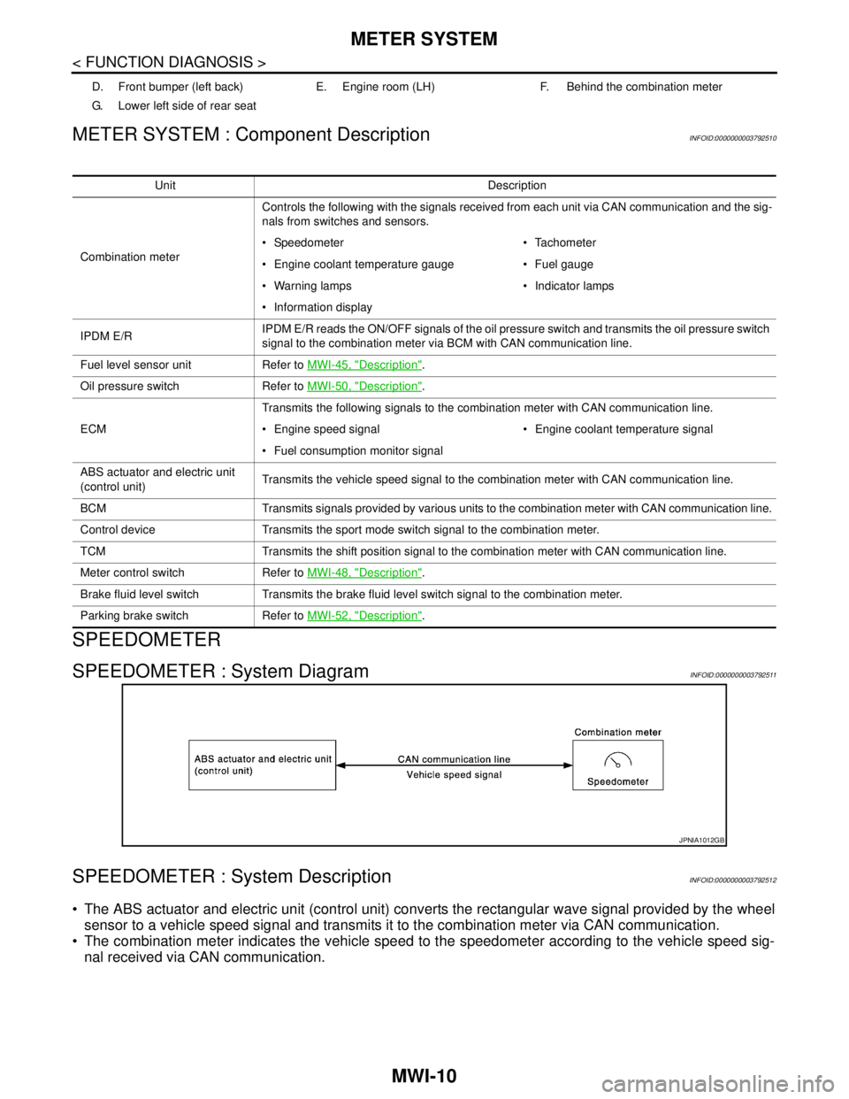
SPEEDOMETER : System DiagramINFOID:0000000003792511
SPEEDOMETER : System DescriptionINFOID:0000000003792512
The ABS actuator and electric unit (control unit) converts the rectangular wave signal provided by the wheel
sensor to a vehicle speed signal and transmits it to the combination meter via CAN communication.
The combination meter indicates the vehicle speed to the speedometer according to the vehicle speed sig-
nal received via CAN communication.
D. Front bumper (left back) E. Engine room (LH) F. Behind the combination meter
G. Lower left side of rear seat
Unit Description
Combination meterControls the following with the signals received from each unit via CAN communication and the sig-
nals from switches and sensors.
Speedometer Tachometer
Engine coolant temperature gauge Fuel gauge
Warning lamps Indicator lamps
Information display
IPDM E/RIPDM E/R reads the ON/OFF signals of the oil pressure switch and transmits the oil pressure switch
signal to the combination meter via BCM with CAN communication line.
Fuel level sensor unit Refer to MWI-45, "
Description".
Oil pressure switch Refer to MWI-50, "
Description".
ECMTransmits the following signals to the combination meter with CAN communication line.
Engine speed signal Engine coolant temperature signal
Fuel consumption monitor signal
ABS actuator and electric unit
(control unit)Transmits the vehicle speed signal to the combination meter with CAN communication line.
BCM Transmits signals provided by various units to the combination meter with CAN communication line.
Control device Transmits the sport mode switch signal to the combination meter.
TCM Transmits the shift position signal to the combination meter with CAN communication line.
Meter control switch Refer to MWI-48, "
Description".
Brake fluid level switch Transmits the brake fluid level switch signal to the combination meter.
Parking brake switch Refer to MWI-52, "
Description".
JPNIA1012GB
Page 3282 of 5121

MWI-28
< FUNCTION DIAGNOSIS >
METER SYSTEM
LOW FUEL WARNING
The combination meter indicates the low fuel warning judged by the fuel level sensor signal received from the
fuel level sensor unit.
Warning operation condition
Fuel level: Approx. 11 (2 - 2/5 Imp gal) or less
DOOR/TRUNK OPEN WARNING
The combination meter indicates the door open warning judged by each door switch signal received from the
BCM via CAN communication line.
The combination meter indicates the trunk open warning judged by trunk switch signal received from the
BCM via CAN communication line.
INSTANTANEOUS FUEL CONSUMPTION
The combination meter receives the fuel consumption monitor signal from the ECM and the vehicle speed
signal from the ABS actuator and electric unit (control unit) via CAN communication.
The combination meter calculates instantaneous fuel consumption according to the fuel consumption moni-
tor signal and the vehicle speed signal received via CAN communication.
AVERAGE FUEL CONSUMPTION
The combination meter receives the fuel consumption monitor signal from the ECM and the vehicle speed
signal from the ABS actuator and electric unit (control unit) via CAN communication.
The combination meter calculates the average fuel consumption according to the fuel consumption monitor
signal and the vehicle speed signal received via CAN communication.
The average fuel consumption displayed on the information display is uploaded in approximately 30-second
intervals.
NOTE:
When turning ON the ignition switch after triggering a reset or removing/installing the battery, “−−−−” is indi-
cated until 30 seconds/500 m (0.31 miles) of driving.
AVERAGE VEHICLE SPEED
The combination meter receives the vehicle speed signal from the ABS actuator and electric unit (control
unit) via CAN communication.
Measures the time while the ignition switch is ON through the combination meter.
The combination meter the average vehicle speed according to the above signals.
The average vehicle speed displayed on the information display is uploaded in approximately 30-second
intervals.
NOTE:
When turning ON the ignition switch after triggering a reset or removing/installing the battery, “−−−−” is indi-
cated until 30 seconds/500 m (0.31 miles) of driving.
TRAVEL TIME
Measures the time while the ignition switch is ON through the combination meter.
TRAVEL DISTANCE
The combination meter receives the vehicle speed signal from the ABS actuator and electric unit (control
unit) via CAN communication.
The combination meter calculates the vehicle distance according to the vehicle speed signal. The vehicle
distance is displayed.
POSSIBLE DRIVING DISTANCE
The combination meter calculates possible driving distance according to the vehicle speed signal and fuel
consumption monitor signal transmitted via CAN communication and the fuel level sensor signal transmitted
from the fuel level sensor.
NOTE:
When turning ON the ignition switch after removing/installing the battery, “−−−−” is indicated until 30 sec-
onds.
The indicated values may not match each other when refueling with the ignition switch ON. Refer to MWI-
124, "INFORMATION DISPLAY : Description".
AMBIENT AIR TEMPERATURE
The combination meter receives the ambient sensor signal from the ambient sensor.
The combination meter calculates the ambient temperature according to the ambient sensor signal.
The indicated temperature does not increase if the vehicle speed is less than 20 km/h (12 MPH).
Page 3285 of 5121
MWI
METER SYSTEM
MWI-31
< FUNCTION DIAGNOSIS >
C
D
E
F
G
H
I
J
K
L
MB A
O
P
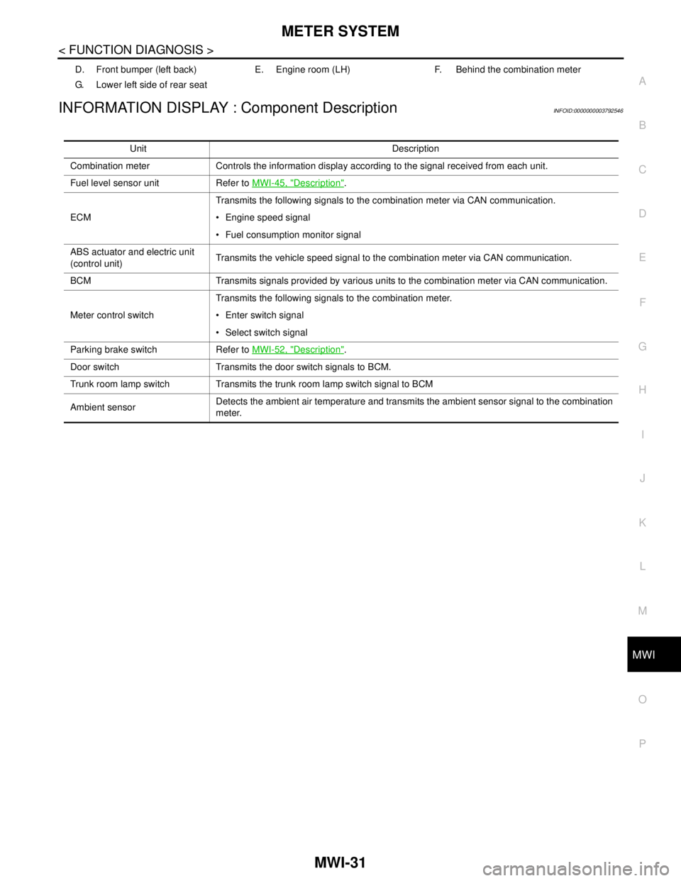
INFORMATION DISPLAY : Component DescriptionINFOID:0000000003792546
D. Front bumper (left back) E. Engine room (LH) F. Behind the combination meter
G. Lower left side of rear seat
Unit Description
Combination meter Controls the information display according to the signal received from each unit.
Fuel level sensor unit Refer to MWI-45, "
Description".
ECMTransmits the following signals to the combination meter via CAN communication.
Engine speed signal
Fuel consumption monitor signal
ABS actuator and electric unit
(control unit)Transmits the vehicle speed signal to the combination meter via CAN communication.
BCM Transmits signals provided by various units to the combination meter via CAN communication.
Meter control switchTransmits the following signals to the combination meter.
Enter switch signal
Select switch signal
Parking brake switch Refer to MWI-52, "
Description".
Door switch Transmits the door switch signals to BCM.
Trunk room lamp switch Transmits the trunk room lamp switch signal to BCM
Ambient sensorDetects the ambient air temperature and transmits the ambient sensor signal to the combination
meter.
Page 3321 of 5121

MWI
COMBINATION METER
MWI-67
< ECU DIAGNOSIS >
C
D
E
F
G
H
I
J
K
L
MB A
O
P
DTC IndexINFOID:0000000003792591
Function Specifications
Speedometer
Reset to zero by suspending communication. Tachometer
Water temperature gauge
Illumination controlWhen suspending communication, changes to nighttime
mode.
Information displayDoor open warning
The display turns off by suspending communication. Trunk open warning
Parking brake release warning
Instantaneous fuel warning When reception time of an abnormal signal is 2 seconds or
less, the last received datum is used for calculation to indi-
cate the result.
When reception time of an abnormal signal is more than two
seconds, the last result calculated during normal condition
is indicated. Average fuel consumption
Average vehicle speed
Travel distance
Buzzer The buzzer turns off by suspending communication.
Warning lamp/indicator
lampABS warning lamp
The lamp turns on by suspending communication. VDC OFF indicator lamp
SLIP indicator lamp
Brake warning lamp
High beam indicator lamp
The lamp turns off by suspending communication. Front fog light indicator lamp
Rear fog light indicator lamp
Turn signal indicator lamp
Light indicator lamp
Oil pressure warning lamp
Malfunction indicator lamp
CRUISE indicator lamp
SPORT indicator lamp
Key warning lamp
Display contents of CONSULT-III Diagnostic item is detected when ... Refer to
CAN COMM CIRCUIT
[U1000]When combination meter is not transmitting or receiving CAN communication signal
for 2 seconds or more.MWI-37,
"Diagnosis
Procedure"
CONTROL UNIT (CAN)
[U1010]When detecting error during the initial diagnosis of the CAN controller of combina-
tion meter.MWI-38, "Diagnosis
Procedure"
VEHICLE SPEED
[B2205]The abnormal vehicle speed signal is input from the ABS actuator and electric unit
(control unit) for 2 seconds or more.MWI-39, "Diagnosis
Procedure"
ENGINE SPEED
[B2267]If ECM continuously transmits abnormal engine speed signals for 2 seconds or
more.MWI-40, "Diagnosis
Procedure"
WATER TEMP
[B2268]If ECM continuously transmits abnormal engine coolant temperature signals for 60
seconds or more.MWI-41, "Diagnosis
Procedure"
Page 4970 of 5121

WCS-40
< ECU DIAGNOSIS >
COMBINATION METER
DTC Index
INFOID:0000000003838733
Function Specifications
Speedometer
Reset to zero by suspending communication. Tachometer
Water temperature gauge
Illumination controlWhen suspending communication, changes to nighttime
mode.
Information displayDoor open warning
The display turns off by suspending communication. Trunk open warning
Parking brake release warning
Instantaneous fuel warning When reception time of an abnormal signal is 2 seconds or
less, the last received datum is used for calculation to indi-
cate the result.
When reception time of an abnormal signal is more than two
seconds, the last result calculated during normal condition
is indicated. Average fuel consumption
Average vehicle speed
Travel distance
Buzzer The buzzer turns off by suspending communication.
Warning lamp/indicator
lampABS warning lamp
The lamp turns on by suspending communication. VDC OFF indicator lamp
SLIP indicator lamp
Brake warning lamp
High beam indicator lamp
The lamp turns off by suspending communication. Front fog light indicator lamp
Rear fog light indicator lamp
Turn signal indicator lamp
Light indicator lamp
Oil pressure warning lamp
Malfunction indicator lamp
CRUISE indicator lamp
SPORT indicator lamp
Key warning lamp
Display contents of CONSULT-III Diagnostic item is detected when ... Refer to
CAN COMM CIRCUIT
[U1000]When combination meter is not transmitting or receiving CAN communication signal
for 2 seconds or more.MWI-37,
"Diagnosis
Procedure"
CONTROL UNIT (CAN)
[U1010]When detecting error during the initial diagnosis of the CAN controller of combina-
tion meter.MWI-38, "Diagnosis
Procedure"
VEHICLE SPEED
[B2205]The abnormal vehicle speed signal is input from the ABS actuator and electric unit
(control unit) for 2 seconds or more.MWI-39, "Diagnosis
Procedure"
ENGINE SPEED
[B2267]If ECM continuously transmits abnormal engine speed signals for 2 seconds or
more.MWI-40, "Diagnosis
Procedure"
WATER TEMP
[B2268]If ECM continuously transmits abnormal engine coolant temperature signals for 60
seconds or more.MWI-41, "Diagnosis
Procedure"