interior NISSAN TEANA 2008 User Guide
[x] Cancel search | Manufacturer: NISSAN, Model Year: 2008, Model line: TEANA, Model: NISSAN TEANA 2008Pages: 5121, PDF Size: 69.03 MB
Page 837 of 5121

BCS-20
< FUNCTION DIAGNOSIS >
DIAGNOSIS SYSTEM (BCM)
*: Factory setting
DATA MONITOR
Service item Setting item Setting
SET I/L D-UNLCK INTCONOn* With the interior room lamp timer function
Off Without the interior room lamp timer function
ROOM LAMP TIMER SETMODE 2 7.5 sec.
Sets the interior room lamp ON time. (Timer operating time) MODE 3* 15 sec.
MODE 4 30 sec.
ROOM LAMP ON TIME SETMODE 1 0.5 sec.
Sets the interior room lamp gradual brightening time. MODE 2* 1 sec.
MODE 3 2 sec.
MODE 4 3 sec.
MODE 5 0 sec.
ROOM LAMP OFF TIME SETMODE 1 0.5 sec.
Sets the interior room lamp gradual dimming time. MODE 2 1 sec.
MODE 3 2 sec.
MODE 4* 3 sec.
MODE 5 0 sec.
R LAMP TIMER LOGIC SETMODE 1* Interior room lamp timer activates with synchronizing all doors.
MODE 2Interior room lamp timer activates with synchronizing the driver door
only.
Monitor item
[Unit]Description
REQ SW-DR
[On/Off]The switch status input from request switch (driver side)
REQ SW-AS
[On/Off]The switch status input from front request switch (passenger side)
PUSH SW
[On/Off]The switch status input from push-button ignition switch
KEY SW-SLOT
[On/Off]Key switch status input from key slot
DOOR SW-DR
[On/Off]The switch status input from front door switch (driver side)
DOOR SW-AS
[On/Off]The switch status input from front door switch (passenger side)
DOOR SW-RR
[On/Off]The switch status input from rear door switch RH
DOOR SW- RL
[On/Off]The switch status input from rear door switch LH
DOOR SW-BK
[On/Off]NOTE:
The item is indicated, but not monitored.
CDL LOCK SW
[On/Off]Lock switch status received from door lock/unlock switch
CDL UNLOCK SW
[On/Off]Unlock switch status received from door lock/unlock switch
KEY CYL LK-SW
[On/Off]NOTE:
The item is indicated, but not monitored.
KEY CYL UN-SW
[On/Off]NOTE:
The item is indicated, but not monitored.
Page 838 of 5121

BCS
DIAGNOSIS SYSTEM (BCM)
BCS-21
< FUNCTION DIAGNOSIS >
C
D
E
F
G
H
I
J
K
L B A
O
P N
ACTIVE TEST
HEADLAMP
HEADLAMP : CONSULT-III Function (BCM - HEAD LAMP)INFOID:0000000003897061
WORK SUPPORT
*: Factory setting
DATA MONITOR
TRNK/HAT MNTR
[On/Off]The switch status input from trunk room lamp switch
RKE-LOCK
[On/Off]Lock signal status received from remote keyless entry receiver
RKE-UNLOCK
[On/Off]Unlock signal status received from remote keyless entry receiver Monitor item
[Unit]Description
Test item Operation Description
INT LAMPOnOutputs the interior room lamp control signal to turn map lamp and personal lamp ON
(Map lamp switch is in DOOR position).
Off Stops the interior room lamp control signal to turn map lamp and personal lamp OFF.
STEP LAMP TESTOn Outputs the step lamp control signal to turn step lamp ON.
Off Stops the step lamp control signal to turn step lamp OFF.
LUGGAGE LAMP TESTOn Outputs the trunk room lamp control signal to turn trunk room lamp ON.
Off Stops the trunk room lamp control signal to turn trunk room lamp OFF.
Service item Setting item Setting
BATTERY SAVER SETOn* With the exterior lamp battery saver function
Off Without the exterior lamp battery saver function
ILL DELAY SETMODE 1* 45 sec.
Sets delay timer function timer operation time.
(All doors closed) MODE 2Without the func-
tion
MODE 3 30 sec.
MODE 4 60 sec.
MODE 5 90 sec.
MODE 6 120 sec.
MODE 7 150 sec.
MODE 8 180 sec.
CUSTOM A/LIGHT SET-
TINGMODE 1* Normal
MODE 2 More sensitive setting than normal setting (Turns ON earlier than normal operation.)
MODE 3 More sensitive setting than MODE 2 (Turns ON earlier than MODE 2.)
MODE 4 Less sensitive setting than normal setting (Turns ON later than normal operation.)
Monitor item
[Unit]Description
PUSH SW
[On/Off]The switch status input from push-button ignition switch
ENGINE STATE
[Stop/Stall/Crank/Run]The engine status received from ECM with CAN communication
Page 844 of 5121

BCS
DIAGNOSIS SYSTEM (BCM)
BCS-27
< FUNCTION DIAGNOSIS >
C
D
E
F
G
H
I
J
K
L B A
O
P N
ACTIVE TEST
RKE-PANICNOTE:
This item is displayed, but cannot be monitored.
RKE-P/W OPENNOTE:
This item is displayed, but cannot be monitored.
RKE-MODE CHG Indicates [ON/OFF] condition of MODE CHANGE signal from Intelligent Key.
RKE OPE COUN1When remote keyless entry receiver receives the signal transmitted while operating on Intelligent Key, the
numerical values start changing.
RKE OPE COUN2NOTE:
This item is displayed, but cannot be monitored. Monitor Item Condition
Test item Description
BATTERY SAVERThis test is able to check interior room lamp operation.
The interior room lamp will be activated when “ON” on CONSULT-III screen is touched.
PW REMOTO DOWN SETNOTE:
This item is displayed, but cannot be used.
OUTSIDE BUZZERThis test is able to check Intelligent Key warning buzzer operation.
The Intelligent Key warning buzzer will be activated when “ON” on CONSULT-III screen is touched.
INSIDE BUZZERThis test is able to check warning chime in combination meter operation.
Take away warning chime sounds when “TAKE OUT” on CONSULT-III screen is touched.
Key warning chime sounds when “KEY” on CONSULT-III screen is touched.
P position warning chime sounds when “KNOB” on CONSULT-III screen is touched.
INDICATORThis test is able to check warning lamp operation.
“KEY” Warning lamp illuminates when “RED ON” on CONSULT-III screen is touched.
“KEY” Warning lamp blinks when “RED IND” on CONSULT-III screen is touched.
INT LAMPThis test is able to check interior room lamp operation.
The interior room lamp will be activated when “ON” on CONSULT-III screen is touched.
LCDThis test is able to check meter display information
Engine start information displays when “BP N” on CONSULT-III screen is touched.
Engine start information displays when “BP I” on CONSULT-III screen is touched.
Key ID warning displays when “ID NG” on CONSULT-III screen is touched.
Steering lock information displays when “ROTAT” on CONSULT-III screen is touched.
P position warning displays when “SFT P” on CONSULT-III screen is touched.
Intelligent Key insert information displays when “INSRT” on CONSULT-III screen is touched.
Intelligent Key low battery warning displays when “BATT” on CONSULT-III screen is touched.
Take away warning displays when “OUTKEY” on CONSULT-III screen is touched.
OFF position warning displays when “LK WN” on CONSULT-III screen is touched.
TRUNK/GLASS HATCHThis test is able to check trunk lid opener actuator open operation.
This actuator opens when “OPEN” on CONSULT-III screen is touched.
FLASHERThis test is able to check security hazard lamp operation.
The hazard lamps will be activated when “RH” or “LH”on CONSULT-III screen is touched.
HORNThis test is able to check horn operation.
The horn will be activated when “ON” on CONSULT-III screen is touched.
P RANGEThis test is able to check control device power supply
Control device power is supplied when “ON” on CONSULT-III screen is touched.
ENGINE SW ILLUMIThis test is able to check push-ignition switch illumination operation.
Push-ignition switch illumination illuminates when “ON” on CONSULT-III screen is touched.
LOCK INDICATORThis test is able to check LOCK indicator in push-ignition switch operation.
LOCK indicator in push-ignition switch illuminates when “ON” on CONSULT-III screen is touched.
ACC INDICATORThis test is able to check ACC indicator in push-ignition switch operation.
ACC indicator in push-ignition switch illuminates when “ON” on CONSULT-III screen is touched.
IGNITION ON INDThis test is able to check ON indicator in push-ignition switch operation.
ON indicator in push-ignition switch illuminates when “ON” on CONSULT-III screen is touched.
Page 846 of 5121

BCS
DIAGNOSIS SYSTEM (BCM)
BCS-29
< FUNCTION DIAGNOSIS >
C
D
E
F
G
H
I
J
K
L B A
O
P N
When performed “RESET SETTING VALUE” on “Work Support (BCM - BCM)”, set “WIPER SPEED SETTING” on “Work Support (BCM
- WIPER)” to “On”.
IMMU
IMMU : CONSULT-III Function (BCM - IMMU)INFOID:0000000003897057
APPLICATION ITEM
CONSULT-III performs the following functions via CAN communication with BCM.
DATA MONITOR
ACTIVE TEST
BATTERY SAVER
BATTERY SAVER : CONSULT-III Function (BCM - BATTERY SAVER)INFOID:0000000003897060
WORK SUPPORT
*: Factory setting
DATA MONITOR
Diagnosis mode Function Description
DATA MONITOR The BCM input/output signals are displayed.
ACTIVE TEST The signals used to activate each device are forcibly supplied from BCM.
Monitor item Content
CONFRM ID ALL
Indicates [YET] at all time.
Switches to [DONE] when a registered Intelligent Key is inserted into the key slot. CONFIRM ID4
CONFIRM ID3
CONFIRM ID2
CONFIRM ID1
TP 4
Indicates the number of ID which has been registered. TP 3
TP 2
TP 1
PUSH SW Indicates [ON/OFF] condition of push-button ignition switch.
KEY SW -SLOT Indicates [ON/OFF] condition of key slot.
Test item Description
THEFT INDThis test is able to check security indicator lamp operation.
The lamp will be turned on when “ON” on CONSULT-III screen touched.
Service item Setting item Setting
BATTERY SAVER SETOn* With the exterior lamp battery saver function
Off Without the exterior lamp battery saver function
ROOM LAMP BAT SAV SETOn* With the interior room lamp battery saver function
Off Without the interior room lamp battery saver function
ROOM LAMP TIMER SETMODE 1* 30 min.
Sets the interior room lamp battery saver timer operating
time.
MODE 2 60 min.
Page 847 of 5121

BCS-30
< FUNCTION DIAGNOSIS >
DIAGNOSIS SYSTEM (BCM)
ACTIVE TEST
*: Each lamp switch is in ON position.
TRUNK
TRUNK : CONSULT-III Function (BCM - TRUNK)INFOID:0000000003897054
BCM CONSULT-III FUNCTION
CONSULT-III performs the following functions via CAN communication with BCM.
DATA MONITOR
Monitor item
[Unit]Description
REQ SW-DR
[On/Off]The switch status input from request switch (driver side)
REQ SW-AS
[On/Off]The switch status input from front request switch (passenger side)
PUSH SW
[On/Off]The switch status input from push-button ignition switch
KEY SW-SLOT
[On/Off]Key switch status input from key slot
DOOR SW-DR
[On/Off]The switch status input from front door switch (driver side)
DOOR SW-AS
[On/Off]The switch status input from front door switch (passenger side)
DOOR SW-RR
[On/Off]The switch status input from rear door switch RH
DOOR SW- RL
[On/Off]The switch status input from rear door switch LH
DOOR SW-BK
[On/Off]NOTE:
The item is indicated, but not monitored.
CDL LOCK SW
[On/Off]Lock switch status received from door lock/unlock switch
CDL UNLOCK SW
[On/Off]Unlock switch status received from door lock/unlock switch
KEY CYL LK-SW
[On/Off]NOTE:
The item is indicated, but not monitored.
KEY CYL UN-SW
[On/Off]NOTE:
The item is indicated, but not monitored.
TRNK/HAT MNTR
[On/Off]The switch status input from trunk room lamp switch
RKE-LOCK
[On/Off]Lock signal status received from remote keyless entry receiver
RKE-UNLOCK
[On/Off]Unlock signal status received from remote keyless entry receiver
Test item Operation Description
BATTERY SAVEROff Cuts the interior room lamp power supply to turn interior room lamp OFF.
On Outputs the interior room lamp power supply to turn interior room lamp ON.*
Diagnosis mode Function Description
DATA MONITOR The BCM input/output signals are displayed.
ACTIVE TEST The signals used to activate each device are forcibly supplied from BCM.
Page 864 of 5121

BCS
BCM (BODY CONTROL MODULE)
BCS-47
< ECU DIAGNOSIS >
C
D
E
F
G
H
I
J
K
L B A
O
P N
PHYSICAL VALUES
Te r m i n a l N o .
(Wire color)Description
ConditionVa l u e
(Approx.)
Signal nameInput/
Output +–
1
(W/B)GroundBattery power sup-
plyInput Ignition switch OFF Battery voltage
2
(R/Y)GroundP/W power supply
(BAT)Output Ignition switch OFF Battery voltage
3
(L/W)GroundP/W power supply
(IGN)Output Ignition switch ON Battery voltage
4
(P/W)GroundInterior room lamp
power supplyOutputInterior room lamp battery saver is activated.
(Cuts the interior room lamp power supply)0 V
Interior room lamp battery saver is not activat-
ed.
(Outputs the interior room lamp power supply)Battery voltage
5
(G/Y)GroundPassenger door
UNLOCKOutput Passenger doorUNLOCK (Actuator is ac-
tivated)Battery voltage
Other than UNLOCK (Ac-
tuator is not activated)0 V
7
(R/W)Ground Step lamp Output Step lampON 0 V
OFF Battery voltage
8
(V)Ground All doors LOCK Output All doorsLOCK (Actuator is acti-
vated)Battery voltage
Other than LOCK (Actua-
tor is not activated)0 V
9
(G)GroundDriver door UN-
LOCKOutput Driver doorUNLOCK (Actuator is ac-
tivated)Battery voltage
Other than UNLOCK (Ac-
tuator is not activated)0 V
10
(G/Y)GroundRear RH door and
rear LH door UN-
LOCKOutputRear RH door
and rear LH doorUNLOCK (Actuator is ac-
tivated)Battery voltage
Other than UNLOCK (Ac-
tuator is not activated)0 V
11
(Y/R)GroundBattery power sup-
plyInput Ignition switch OFF Battery voltage
13
(B)
Ground Ground — Ignition switch ON 0 V
15
(Y)Ground ACC indicator lamp Output Ignition switchOFF (LOCK indicator is
not illuminated)Battery voltage
ACC or ON 0 V
17
(G/B)GroundTurn signal RH
(Front and door mir-
ror)OutputIgnition switch
ONTurn signal switch OFF 0 V
Turn signal switch RH
6.5 V
PKID0926E
Page 865 of 5121
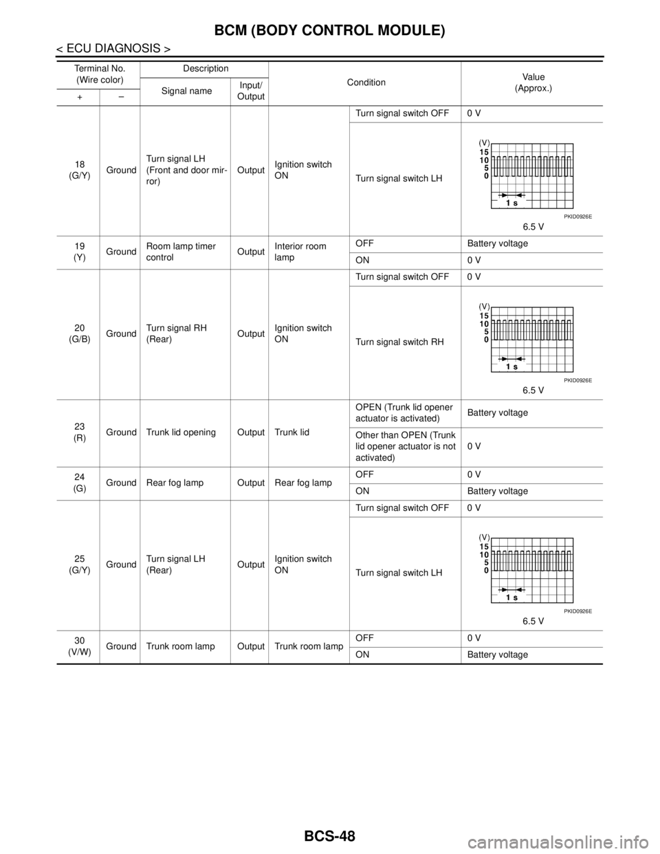
BCS-48
< ECU DIAGNOSIS >
BCM (BODY CONTROL MODULE)
18
(G/Y)GroundTurn signal LH
(Front and door mir-
ror)OutputIgnition switch
ONTurn signal switch OFF 0 V
Turn signal switch LH
6.5 V
19
(Y)GroundRoom lamp timer
controlOutputInterior room
lampOFF Battery voltage
ON 0 V
20
(G/B)GroundTurn signal RH
(Rear)OutputIgnition switch
ONTurn signal switch OFF 0 V
Turn signal switch RH
6.5 V
23
(R)Ground Trunk lid opening Output Trunk lidOPEN (Trunk lid opener
actuator is activated)Battery voltage
Other than OPEN (Trunk
lid opener actuator is not
activated)0 V
24
(G)Ground Rear fog lamp Output Rear fog lampOFF 0 V
ON Battery voltage
25
(G/Y)GroundTurn signal LH
(Rear)OutputIgnition switch
ONTurn signal switch OFF 0 V
Turn signal switch LH
6.5 V
30
(V/W)Ground Trunk room lamp Output Trunk room lampOFF 0 V
ON Battery voltage Te r m i n a l N o .
(Wire color)Description
ConditionVa l u e
(Approx.)
Signal nameInput/
Output +–
PKID0926E
PKID0926E
PKID0926E
Page 1158 of 5121

DEF-8
< FUNCTION DIAGNOSIS >
DIAGNOSIS SYSTEM (BCM)
DIAGNOSIS SYSTEM (BCM)
COMMON ITEM
COMMON ITEM : CONSULT-III Function (BCM - COMMON ITEM)INFOID:0000000003940040
APPLICATION ITEM
CONSULT-III performs the following functions via CAN communication with BCM.
SYSTEM APPLICATION
BCM can perform the following functions for each system.
NOTE:
It can perform the diagnosis modes except the following for all sub system selection items.
×: Applicable item
NOTE:
*: This item is displayed, but is not used.
FREEZE FRAME DATA (FFD) AND IGN COUNTER
Freeze Frame Data
Diagnosis mode Function Description
Work Support Changes the setting for each system function.
Self Diagnostic Result Displays the diagnosis results judged by BCM.
CAN Diag Support MonitorMonitors the reception status of CAN communication viewed from BCM. Refer to CONSULT-III opera-
tion manual.
Data Monitor The BCM input/output signals are displayed.
Active Test The signals used to activate each device are forcibly supplied from BCM.
Ecu Identification The BCM part number is displayed.
Configuration Read and save the vehicle specification.
Write the vehicle specification when replacing BCM.
System Sub system selection itemDiagnosis mode
Work Support Data Monitor Active Test
Door lock DOOR LOCK×××
Rear window defogger REAR DEFOGGER××
Warning chime BUZZER××
Interior room lamp timer INT LAMP×××
Exterior lamp HEAD LAMP×××
Wiper and washer WIPER×××
Turn signal and hazard warning lamps FLASHER×××
— AIR CONDITONER*
Intelligent Key system
Engine start systemINTELLIGENT KEY×××
Combination switch COMB SW×
Body control system BCM×
NVIS - NATS IMMU××
Interior room lamp battery saver BATTERY SAVER×××
Trunk lid opener system TRUNK××
Vehicle security system THEFT ALM×××
— RETAINED PWR*×
Signal buffer system SIGNAL BUFFER××
— TPMS (AIR PRESSURE MONITOR)*×××
Page 1181 of 5121
BCM (BODY CONTROL MODULE)
DEF-31
< ECU DIAGNOSIS >
C
D
E
F
G
H
I
J
K
MA
B
DEF
N
O
P
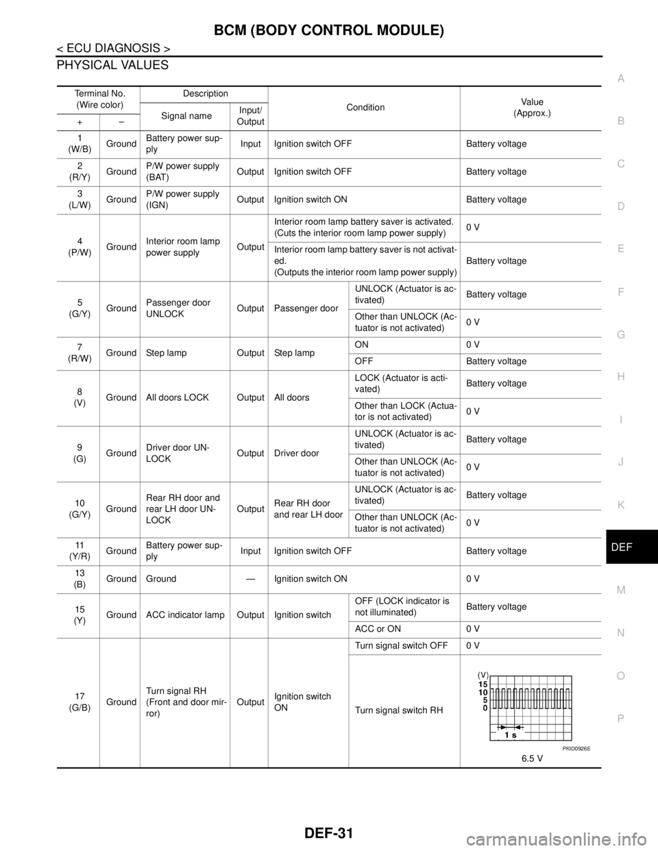
PHYSICAL VALUES
Te r m i n a l N o .
(Wire color)Description
ConditionVa l u e
(Approx.)
Signal nameInput/
Output +–
1
(W/B)GroundBattery power sup-
plyInput Ignition switch OFF Battery voltage
2
(R/Y)GroundP/W power supply
(BAT)Output Ignition switch OFF Battery voltage
3
(L/W)GroundP/W power supply
(IGN)Output Ignition switch ON Battery voltage
4
(P/W)GroundInterior room lamp
power supplyOutputInterior room lamp battery saver is activated.
(Cuts the interior room lamp power supply)0 V
Interior room lamp battery saver is not activat-
ed.
(Outputs the interior room lamp power supply)Battery voltage
5
(G/Y)GroundPassenger door
UNLOCKOutput Passenger doorUNLOCK (Actuator is ac-
tivated)Battery voltage
Other than UNLOCK (Ac-
tuator is not activated)0 V
7
(R/W)Ground Step lamp Output Step lampON 0 V
OFF Battery voltage
8
(V)Ground All doors LOCK Output All doorsLOCK (Actuator is acti-
vated)Battery voltage
Other than LOCK (Actua-
tor is not activated)0 V
9
(G)GroundDriver door UN-
LOCKOutput Driver doorUNLOCK (Actuator is ac-
tivated)Battery voltage
Other than UNLOCK (Ac-
tuator is not activated)0 V
10
(G/Y)GroundRear RH door and
rear LH door UN-
LOCKOutputRear RH door
and rear LH doorUNLOCK (Actuator is ac-
tivated)Battery voltage
Other than UNLOCK (Ac-
tuator is not activated)0 V
11
(Y/R)GroundBattery power sup-
plyInput Ignition switch OFF Battery voltage
13
(B)
Ground Ground — Ignition switch ON 0 V
15
(Y)Ground ACC indicator lamp Output Ignition switchOFF (LOCK indicator is
not illuminated)Battery voltage
ACC or ON 0 V
17
(G/B)GroundTurn signal RH
(Front and door mir-
ror)OutputIgnition switch
ONTurn signal switch OFF 0 V
Turn signal switch RH
6.5 V
PKID0926E
Page 1182 of 5121
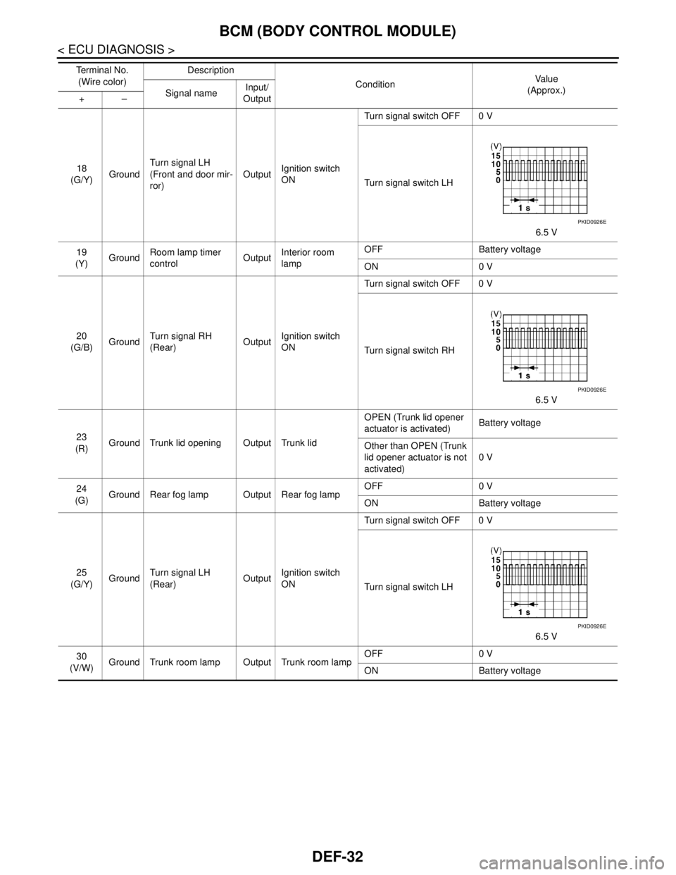
DEF-32
< ECU DIAGNOSIS >
BCM (BODY CONTROL MODULE)
18
(G/Y)GroundTurn signal LH
(Front and door mir-
ror)OutputIgnition switch
ONTurn signal switch OFF 0 V
Turn signal switch LH
6.5 V
19
(Y)GroundRoom lamp timer
controlOutputInterior room
lampOFF Battery voltage
ON 0 V
20
(G/B)GroundTurn signal RH
(Rear)OutputIgnition switch
ONTurn signal switch OFF 0 V
Turn signal switch RH
6.5 V
23
(R)Ground Trunk lid opening Output Trunk lidOPEN (Trunk lid opener
actuator is activated)Battery voltage
Other than OPEN (Trunk
lid opener actuator is not
activated)0 V
24
(G)Ground Rear fog lamp Output Rear fog lampOFF 0 V
ON Battery voltage
25
(G/Y)GroundTurn signal LH
(Rear)OutputIgnition switch
ONTurn signal switch OFF 0 V
Turn signal switch LH
6.5 V
30
(V/W)Ground Trunk room lamp Output Trunk room lampOFF 0 V
ON Battery voltage Te r m i n a l N o .
(Wire color)Description
ConditionVa l u e
(Approx.)
Signal nameInput/
Output +–
PKID0926E
PKID0926E
PKID0926E