interior NISSAN TEANA 2008 Service Manual
[x] Cancel search | Manufacturer: NISSAN, Model Year: 2008, Model line: TEANA, Model: NISSAN TEANA 2008Pages: 5121, PDF Size: 69.03 MB
Page 1 of 5121
MODEL J32 SERIES
© 2008 NISSAN INTERNATIONAL SA
Allrightsreserved.NopartofthisElectronicServiceManualmaybereproducedorstoredinaretrievalsystem,ortransmittedinanyform,or by any means, electronic, mechanical, photocopying, recording or otherwise, without the prior written permission of Nissan InternationalSA, Switzerland.
AGENERALINFORMATION
BENGINE
DTRANSMISSION&DRIVELINE
ESUSPENSION
FBRAKES
GSTEERING
HRESTRAINTS
IVENTILATION,HEATER&AIRCONDITIONER
JBODYINTERIOR
KBODYEXTERIOR,DOOR,ROOF&VEHICLESECURITY
LDRIVERCONTROLS
MELECTRICAL&POWERCONTROL
NDRIVERINFORMATION&MULTIMEDIA
PMAINTENANCE
GIGeneralInformation
EMEngineMechanical
LUEngineLubricationSystem
COEngineCoolingSystem
ECEngineControlSystem
FLFuelSystem
EXExhaustSystem
STRStartingSystem
ACCAcceleratorControlSystem
TMTransaxle &Transmission
FAXFrontAxle
RAXRearAxle
FSUFrontSuspension
RSURearSuspension
WTRoadWheels &Tires
BRBrakeSystem
PBParkingBrakeSystem
BRCBrakeControlSystem
STSteeringSystem
STCSteeringControlSystem
SBSeatBelt
SRSRSAirbag
SRCSRSAirbagControlSystem
VTLVentilationSystem
HAHeater &AirConditioningSystem
HACHeater &AirConditioningControlSystem
INTInterior
IPInstrumentPanel
SESeat
ADPAutomaticDrivePositioner
DLKDoor &Lock
SECSecurityControlSystem
GWGlass &WindowSystem
PWCPowerWindowControlSystem
RFRoof
EXTExterior
MIRMirrors
EXLExteriorLightingSystem
INLInteriorLightingSystem
WWWiper &Washer
DEFDefogger
HRNHorn
PWOPowerOutlet
BCSBodyControlSystem
LANLANSystem
PCSPowerControlSystem
CHGChargingSystem
PGPowerSupply,Ground&CircuitElements
MWIMeter,WarningLamp&Indicator
WCSWarningChimeSystem
AVAudio,Visual&NavigationSystem
MAMaintenance
QUICKREFERENCEINDEX
A
B
C
D
E
F
G
H
I
J
K
L
M
N
O
P
M
Publication Number:
SM8E00-1J32E0E
Page 7 of 5121

ADP-1
BODY INTERIOR
C
D
E
F
G
H
I
K
L
M
SECTION ADP
A
B
ADP
N
O
P
CONTENTS
AUTOMATIC DRIVE POSITIONER
BASIC INSPECTION ....................................4
DIAGNOSIS AND REPAIR WORKFLOW ..........4
Work Flow .................................................................4
INSPECTION AND ADJUSTMENT .....................7
ADDITIONAL SERVICE WHEN REMOVING BAT-
TERY NEGATIVE TERMINAL .....................................
7
ADDITIONAL SERVICE WHEN REMOVING
BATTERY NEGATIVE TERMINAL : Description ......
7
ADDITIONAL SERVICE WHEN REMOVING
BATTERY NEGATIVE TERMINAL : Special Re-
pair Requirement .......................................................
7
ADDITIONAL SERVICE WHEN REPLACING
CONTROL UNIT ..........................................................
7
ADDITIONAL SERVICE WHEN REPLACING
CONTROL UNIT : Description ..................................
7
ADDITIONAL SERVICE WHEN REPLACING
CONTROL UNIT : Special Repair Requirement .......
7
SYSTEM INITIALIZATION ..........................................8
SYSTEM INITIALIZATION : Description ...................8
SYSTEM INITIALIZATION : Special Repair Re-
quirement ..................................................................
8
MEMORY STORING ....................................................8
MEMORY STORING : Description ............................8
MEMORY STORING : Special Repair Require-
ment ..........................................................................
9
SYSTEM SETTING ......................................................9
SYSTEM SETTING : Description ..............................9
SYSTEM SETTING : Special Repair Requirement
....
10
FUNCTION DIAGNOSIS ..............................12
AUTOMATIC DRIVE POSITIONER SYSTEM ....12
AUTOMATIC DRIVE POSITIONER SYSTEM ...........12
AUTOMATIC DRIVE POSITIONER SYSTEM :
System Diagram ......................................................
12
AUTOMATIC DRIVE POSITIONER SYSTEM :
System Description ..................................................
12
AUTOMATIC DRIVE POSITIONER SYSTEM :
Component Parts Location ......................................
14
AUTOMATIC DRIVE POSITIONER SYSTEM :
Component Description ..........................................
15
MANUAL FUNCTION ................................................16
MANUAL FUNCTION : System Diagram ................16
MANUAL FUNCTION : System Description ............16
MANUAL FUNCTION : Component Parts Loca-
tion ...........................................................................
17
MANUAL FUNCTION : Component Description .....18
MEMORY FUNCTION ................................................18
MEMORY FUNCTION : System Diagram ...............19
MEMORY FUNCTION : System Description ...........19
MEMORY FUNCTION : Component Parts Loca-
tion ...........................................................................
21
MEMORY FUNCTION : Component Description ....22
EXIT ASSIST FUNCTION ..........................................22
EXIT ASSIST FUNCTION : System Diagram ..........23
EXIT ASSIST FUNCTION : System Description .....23
EXIT ASSIST FUNCTION : Component Parts Lo-
cation .......................................................................
25
EXIT ASSIST FUNCTION :
Component Description ..........................................
26
ENTRY ASSIST FUNCTION ......................................26
ENTRY ASSIST FUNCTION : System Diagram .....27
ENTRY ASSIST FUNCTION : System Description
....
27
ENTRY ASSIST FUNCTION : Component Parts
Location ...................................................................
29
ENTRY ASSIST FUNCTION :
Component Description ..........................................
30
INTELLIGENT KEY INTERLOCK FUNCTION ..........30
Page 89 of 5121
BCM (BODY CONTROL MODULE)
ADP-83
< COMPONENT DIAGNOSIS >
C
D
E
F
G
H
I
K
L
MA
B
ADP
N
O
P
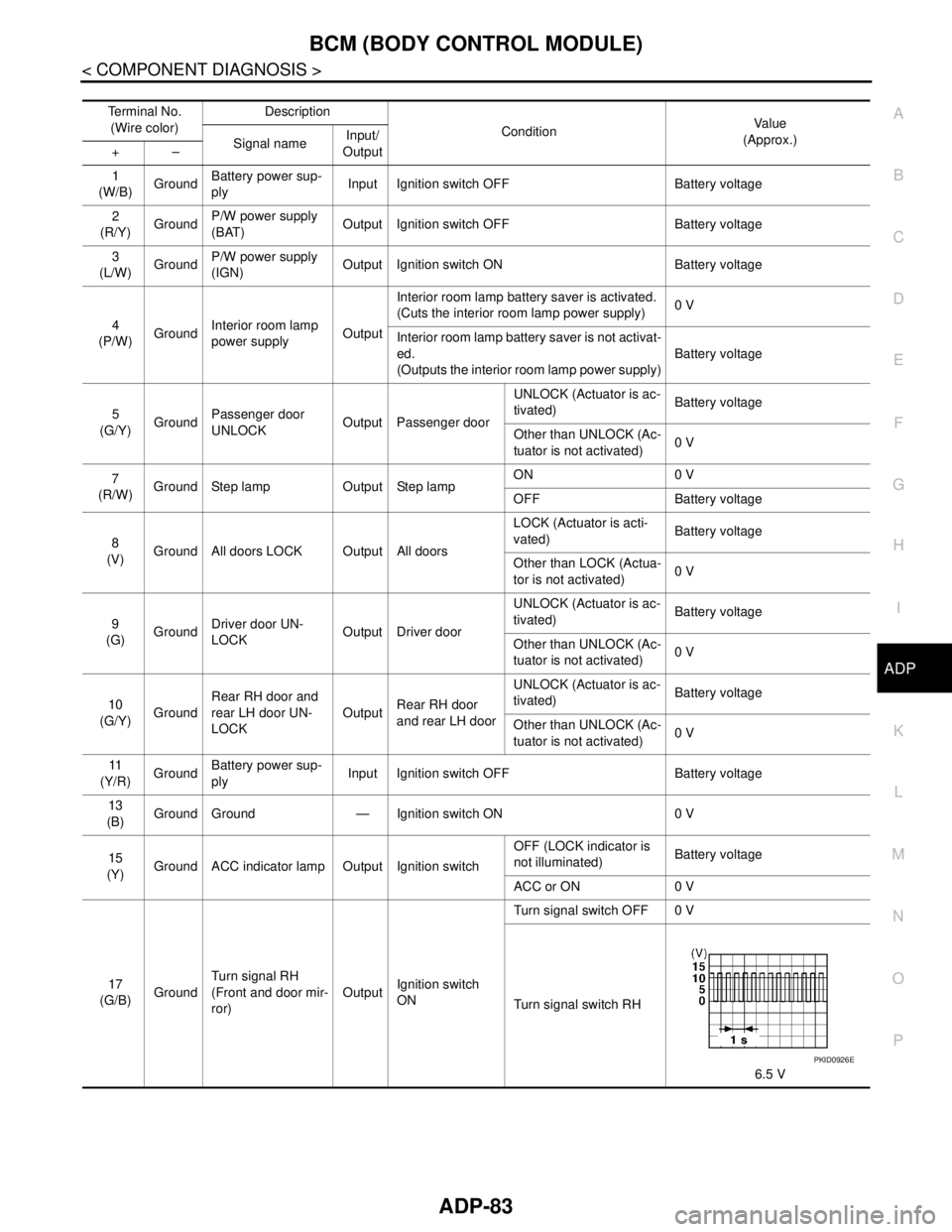
Te r m i n a l N o .
(Wire color)Description
ConditionVa l u e
(Approx.)
Signal nameInput/
Output +–
1
(W/B)GroundBattery power sup-
plyInput Ignition switch OFF Battery voltage
2
(R/Y)GroundP/W power supply
(BAT)Output Ignition switch OFF Battery voltage
3
(L/W)GroundP/W power supply
(IGN)Output Ignition switch ON Battery voltage
4
(P/W)GroundInterior room lamp
power supplyOutputInterior room lamp battery saver is activated.
(Cuts the interior room lamp power supply)0 V
Interior room lamp battery saver is not activat-
ed.
(Outputs the interior room lamp power supply)Battery voltage
5
(G/Y)GroundPassenger door
UNLOCKOutput Passenger doorUNLOCK (Actuator is ac-
tivated)Battery voltage
Other than UNLOCK (Ac-
tuator is not activated)0 V
7
(R/W)Ground Step lamp Output Step lampON 0 V
OFF Battery voltage
8
(V)Ground All doors LOCK Output All doorsLOCK (Actuator is acti-
vated)Battery voltage
Other than LOCK (Actua-
tor is not activated)0 V
9
(G)GroundDriver door UN-
LOCKOutput Driver doorUNLOCK (Actuator is ac-
tivated)Battery voltage
Other than UNLOCK (Ac-
tuator is not activated)0 V
10
(G/Y)GroundRear RH door and
rear LH door UN-
LOCKOutputRear RH door
and rear LH doorUNLOCK (Actuator is ac-
tivated)Battery voltage
Other than UNLOCK (Ac-
tuator is not activated)0 V
11
(Y/R)GroundBattery power sup-
plyInput Ignition switch OFF Battery voltage
13
(B)
Ground Ground — Ignition switch ON 0 V
15
(Y)Ground ACC indicator lamp Output Ignition switchOFF (LOCK indicator is
not illuminated)Battery voltage
ACC or ON 0 V
17
(G/B)GroundTurn signal RH
(Front and door mir-
ror)OutputIgnition switch
ONTurn signal switch OFF 0 V
Turn signal switch RH
6.5 V
PKID0926E
Page 90 of 5121
ADP-84
< COMPONENT DIAGNOSIS >
BCM (BODY CONTROL MODULE)
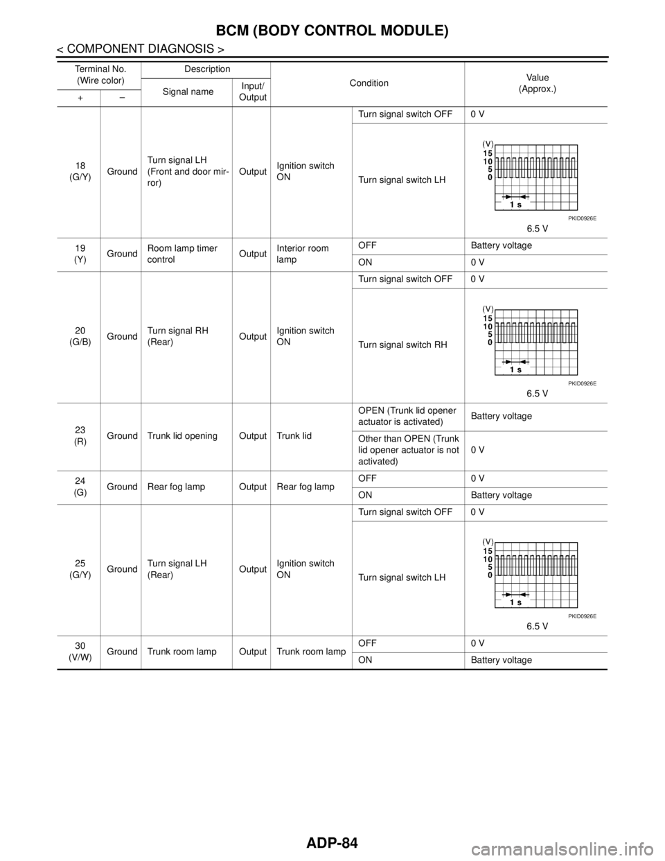
18
(G/Y)GroundTurn signal LH
(Front and door mir-
ror)OutputIgnition switch
ONTurn signal switch OFF 0 V
Turn signal switch LH
6.5 V
19
(Y)GroundRoom lamp timer
controlOutputInterior room
lampOFF Battery voltage
ON 0 V
20
(G/B)GroundTurn signal RH
(Rear)OutputIgnition switch
ONTurn signal switch OFF 0 V
Turn signal switch RH
6.5 V
23
(R)Ground Trunk lid opening Output Trunk lidOPEN (Trunk lid opener
actuator is activated)Battery voltage
Other than OPEN (Trunk
lid opener actuator is not
activated)0 V
24
(G)Ground Rear fog lamp Output Rear fog lampOFF 0 V
ON Battery voltage
25
(G/Y)GroundTurn signal LH
(Rear)OutputIgnition switch
ONTurn signal switch OFF 0 V
Turn signal switch LH
6.5 V
30
(V/W)Ground Trunk room lamp Output Trunk room lampOFF 0 V
ON Battery voltage Te r m i n a l N o .
(Wire color)Description
ConditionVa l u e
(Approx.)
Signal nameInput/
Output +–
PKID0926E
PKID0926E
PKID0926E
Page 311 of 5121
![NISSAN TEANA 2008 Service Manual AV
NORMAL OPERATING CONDITION
AV-167
< SYMPTOM DIAGNOSIS >[BASE AUDIO AND DISPLAY SYSTEM]
C
D
E
F
G
H
I
J
K
L
MB A
O
P
NORMAL OPERATING CONDITION
DescriptionINFOID:0000000003882786
BASIC OPERATIONS
RE](/img/5/57391/w960_57391-310.png "NISSAN TEANA 2008 Service Manual AV
NORMAL OPERATING CONDITION
AV-167
< SYMPTOM DIAGNOSIS >[BASE AUDIO AND DISPLAY SYSTEM]
C
D
E
F
G
H
I
J
K
L
MB A
O
P
NORMAL OPERATING CONDITION
DescriptionINFOID:0000000003882786
BASIC OPERATIONS
RE")
AV
NORMAL OPERATING CONDITION
AV-167
< SYMPTOM DIAGNOSIS >[BASE AUDIO AND DISPLAY SYSTEM]
C
D
E
F
G
H
I
J
K
L
MB A
O
P
NORMAL OPERATING CONDITION
DescriptionINFOID:0000000003882786
BASIC OPERATIONS
RELATED TO AUDIO
The majority of the audio malfunctions are the result of outside causes (bad CD/cassette, electromagnetic
interference, etc.). Check the symptoms below to diagnose the malfunction.
The vehicle itself can be a source of noise if noise prevention parts or electrical equipment is malfunctioning.
Check if noise is caused and/or changed by engine speed, ignition switch turned to each position, and oper-
ation of each piece of electrical equipment, and then determine the cause.
NOTE:
CD-R is not guaranteed to play because they can contain compressed audio (MP3, WMA) or could be incor-
rectly mastered by the customer on a computer.
Check if the CDs carry the Compact Disc Logo. If not, the disc is not mastered to the red book Compact Disc
Standard and may not play.
Symptom Possible cause Possible solution
No image is displayed.The brightness is at the lowest setting. Adjust the brightness of the display.
The system in the video mode. Push
The display is turned off. Push
The screen is too dim. The move-
ment is slow.The temperature in the interior of the vehicle is low. Wait until the interior of the vehicle has
warmed up.
Some pixels in the display are dark-
er or brighter than others.This condition is an inherent characteristic of liquid
crystal displays.This is not a malfunction.
Some menu items cannot be se-
lected.Some menu items become unavailable while the ve-
hicle is driven.Park the vehicle in a safe location, and
then operate the multi AV system.
Symptom Cause and Counter measure
Cannot playCheck if the CD was inserted correctly.
Check if the CD is scratched or dirty.
Check if there is condensation inside the player, and if there is, wait until the condensation is gone
(about 1 hour) before using the player.
If there is a temperature increase error, the player will play correctly after it returns to the normal
temperature.
If there is a mixture of music CD files (CD-DA data) and MP3/WMA files on a CD, only the music
CD files (CD-DA data) will be played.
Files with extensions other than “.MP3”, “.WMA”, “.mp3”, or “.wma” cannot be played. In addition,
the character codes and number of characters for folder names and file names should be in com-
pliance with the specifications.
Check if the disc or the file is generated in an irregular format, This may occur depending on the
variation or the setting of MP3/WMA writing applications or other text editing applications.
Check if the finalization process, such as session close and disc close, is done for the disc.
Check if the CD is protected by copyright.
Poor sound quality Check if the CD is scratched or dirty.
It takes a relatively long time before
the music starts playing.If there are many folder or file levels on the MP3/WMA CD, or if it is a multisession disc, some
time may be required before the music starts playing.
Music cuts off or skipsThe writing software and hardware combination might not match, or the writing speed, writing
depth, writing width might not match the specifications. Try using the slowest writing speed.
Skipping with high bit rate files Skipping may occur with large quantities if data such as for high bit rate data.
Page 519 of 5121
![NISSAN TEANA 2008 Service Manual AV
NORMAL OPERATING CONDITION
AV-375
< SYMPTOM DIAGNOSIS >[BOSE AUDIO WITHOUT NAVIGATION]
C
D
E
F
G
H
I
J
K
L
MB A
O
P
NORMAL OPERATING CONDITION
DescriptionINFOID:0000000003765767
BASIC OPERATIONS
RE](/img/5/57391/w960_57391-518.png "NISSAN TEANA 2008 Service Manual AV
NORMAL OPERATING CONDITION
AV-375
< SYMPTOM DIAGNOSIS >[BOSE AUDIO WITHOUT NAVIGATION]
C
D
E
F
G
H
I
J
K
L
MB A
O
P
NORMAL OPERATING CONDITION
DescriptionINFOID:0000000003765767
BASIC OPERATIONS
RE")
AV
NORMAL OPERATING CONDITION
AV-375
< SYMPTOM DIAGNOSIS >[BOSE AUDIO WITHOUT NAVIGATION]
C
D
E
F
G
H
I
J
K
L
MB A
O
P
NORMAL OPERATING CONDITION
DescriptionINFOID:0000000003765767
BASIC OPERATIONS
RELATED TO AUDIO
The majority of the audio malfunctions are the result of outside causes (bad CD/cassette, electromagnetic
interference, etc.). Check the symptoms below to diagnose the malfunction.
The vehicle itself can be a source of noise if noise prevention parts or electrical equipment is malfunctioning.
Check if noise is caused and/or changed by engine speed, ignition switch turned to each position, and oper-
ation of each piece of electrical equipment, and then determine the cause.
NOTE:
CD-R is not guaranteed to play because they can contain compressed audio (MP3, WMA) or could be incor-
rectly mastered by the customer on a computer.
Check if the CDs carry the Compact Disc Logo. If not, the disc is not mastered to the red book Compact Disc
Standard and may not play.
Symptom Possible cause Possible solution
No image is displayed.The brightness is at the lowest setting. Adjust the brightness of the display.
The system in the video mode. Push
The display is turned off. Push
The screen is too dim. The move-
ment is slow.The temperature in the interior of the vehicle is low. Wait until the interior of the vehicle has
warmed up.
Some pixels in the display are dark-
er or brighter than others.This condition is an inherent characteristic of liquid
crystal displays.This is not a malfunction.
Some menu items cannot be se-
lected.Some menu items become unavailable while the ve-
hicle is driven.Park the vehicle in a safe location, and
then operate the multi AV system.
Symptom Cause and Counter measure
Cannot playCheck if the CD was inserted correctly.
Check if the CD is scratched or dirty.
Check if there is condensation inside the player, and if there is, wait until the condensation is gone
(about 1 hour) before using the player.
If there is a temperature increase error, the player will play correctly after it returns to the normal
temperature.
If there is a mixture of music CD files (CD-DA data) and MP3/WMA files on a CD, only the music
CD files (CD-DA data) will be played.
Files with extensions other than “.MP3”, “.WMA”, “.mp3”, or “.wma” cannot be played. In addition,
the character codes and number of characters for folder names and file names should be in com-
pliance with the specifications.
Check if the disc or the file is generated in an irregular format, This may occur depending on the
variation or the setting of MP3/WMA writing applications or other text editing applications.
Check if the finalization process, such as session close and disc close, is done for the disc.
Check if the CD is protected by copyright.
Poor sound quality Check if the CD is scratched or dirty.
It takes a relatively long time before
the music starts playing.If there are many folder or file levels on the MP3/WMA CD, or if it is a multi session disc, some
time may be required before the music starts playing.
Music cuts off or skipsThe writing software and hardware combination might not match, or the writing speed, writing
depth, writing width might not match the specifications. Try using the slowest writing speed.
Skipping with high bit rate files Skipping may occur with large quantities if data such as for high bit rate data.
Page 789 of 5121
![NISSAN TEANA 2008 Service Manual AV
NORMAL OPERATING CONDITION
AV-645
< SYMPTOM DIAGNOSIS >[BOSE AUDIO WITH NAVIGATION]
C
D
E
F
G
H
I
J
K
L
MB A
O
P
NORMAL OPERATING CONDITION
DescriptionINFOID:0000000003765977
NOTE:
For Navigation s](/img/5/57391/w960_57391-788.png "NISSAN TEANA 2008 Service Manual AV
NORMAL OPERATING CONDITION
AV-645
< SYMPTOM DIAGNOSIS >[BOSE AUDIO WITH NAVIGATION]
C
D
E
F
G
H
I
J
K
L
MB A
O
P
NORMAL OPERATING CONDITION
DescriptionINFOID:0000000003765977
NOTE:
For Navigation s")
AV
NORMAL OPERATING CONDITION
AV-645
< SYMPTOM DIAGNOSIS >[BOSE AUDIO WITH NAVIGATION]
C
D
E
F
G
H
I
J
K
L
MB A
O
P
NORMAL OPERATING CONDITION
DescriptionINFOID:0000000003765977
NOTE:
For Navigation system operation information, refer to Navigation system Owner's Manual.
BASIC OPERATIONS
RELATED TO AUDIO
The majority of the audio malfunctions are the result of outside causes (bad CD/cassette, electromagnetic
interference, etc.). Check the symptoms below to diagnose the malfunction.
The vehicle itself can be a source of noise if noise prevention parts or electrical equipment is malfunctioning.
Check if noise is caused and/or changed by engine speed, ignition switch turned to each position, and oper-
ation of each piece of electrical equipment, and then determine the cause.
NOTE:
CD-R is not guaranteed to play because they can contain compressed audio (MP3, WMA) or could be incor-
rectly mastered by the customer on a computer.
Check if the CDs carry the Compact Disc Logo. If not, the disc is not mastered to the red book Compact Disc
Standard and may not play.
Symptom Possible cause Possible solution
No image is displayed.The brightness is at the lowest setting. Adjust the brightness of the display.
The system in the video mode. Push
The display is turned off.
Push <> to turn on the display.
The screen is too dim. The move-
ment is slow.The temperature in the interior of the vehicle is low. Wait until the interior of the vehicle has
warmed up.
Some pixels in the display are dark-
er or brighter than others.This condition is an inherent characteristic of liquid
crystal displays.This is not a malfunction.
Some menu items cannot be se-
lected.Some menu items become unavailable while the ve-
hicle is driven.Park the vehicle in a safe location, and
then operate the multi AV system.
Symptom Cause and Counter measure
Cannot play.Check if the CD was inserted correctly.
Check if the CD is scratched or dirty.
Check if there is condensation inside the player, and if there is, wait until the condensation is gone
(about 1 hour) before using the player.
If there is a temperature increase error, the player will play correctly after it returns to the normal
temperature.
If there is a mixture of music CD files (CD-DA data) and MP3/WMA files on a CD, only the music
CD files (CD-DA data) will be played.
Files with extensions other than “.MP3”, “.WMA”, “.mp3”, or “.wma” cannot be played. In addition,
the character codes and number of characters for folder names and file names should be in com-
pliance with the specifications.
Check if the disc or the file is generated in an irregular format, This may occur depending on the
variation or the setting of MP3/WMA writing applications or other text editing applications.
Check if the finalization process, such as session close and disc close, is done for the disc.
Check if the CD is protected by copyright.
Poor sound quality. Check if the CD is scratched or dirty.
It takes a relatively long time before
the music starts playing.If there are many folder or file levels on the MP3/WMA disc, some time may be required before
the music starts playing.
Music cuts off or skips.The writing software and hardware combination might not match, or the writing speed, writing
depth, writing width might not match the specifications. Try using the slowest writing speed.
Skipping with high bit rate files. Skipping may occur with large quantities if data such as for high bit rate data.
Page 823 of 5121
BCS-6
< FUNCTION DIAGNOSIS >
BODY CONTROL SYSTEM
FUNCTION DIAGNOSIS
BODY CONTROL SYSTEM
System DescriptionINFOID:0000000003809584
OUTLINE
BCM (Body Control Module) controls the various electrical components. It inputs the information required to
the control from CAN communication and the signal received from each switch and sensor.
BCM has combination switch reading function for reading the operation status of combination switches (light,
turn signal, wiper and washer) in addition to a function for controlling the operation of various electrical com-
ponents. It also has the signal transmission function as the passed point of signal and the power saving con-
trol function that reduces the power consumption with the ignition switch OFF.
BCM is equipped with the diagnosis function that performs the diagnosis with CONSULT-III and various set-
tings.
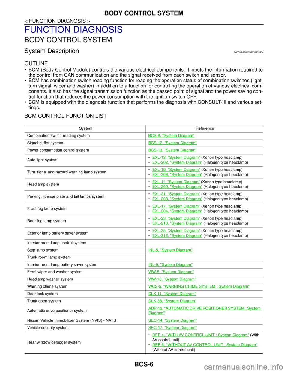
BCM CONTROL FUNCTION LIST
System Reference
Combination switch reading systemBCS-8, "
System Diagram"
Signal buffer systemBCS-12, "System Diagram"
Power consumption control systemBCS-13, "System Diagram"
Auto light systemEXL-13, "System Diagram" (Xenon type headlamp)
EXL-202, "
System Diagram" (Halogen type headlamp)
Turn signal and hazard warning lamp systemEXL-19, "
System Diagram" (Xenon type headlamp)
EXL-206, "
System Diagram" (Halogen type headlamp)
Headlamp systemEXL-11, "
System Diagram" (Xenon type headlamp)
EXL-200, "
System Diagram" (Halogen type headlamp)
Parking, license plate and tail lamps systemEXL-21, "
System Diagram" (Xenon type headlamp)
EXL-208, "
System Diagram" (Halogen type headlamp)
Front fog lamp systemEXL-17, "
System Diagram" (Xenon type headlamp)
EXL-204, "
System Diagram" (Halogen type headlamp)
Rear fog lamp systemEXL-23, "
System Diagram" (Xenon type headlamp)
EXL-210, "
System Diagram" (Halogen type headlamp)
Exterior lamp battery saver systemEXL-25, "
System Diagram" (Xenon type headlamp)
EXL-212, "
System Diagram" (Halogen type headlamp)
Interior room lamp control system
INL-5, "
System Diagram"Step lamp system
Trunk room lamp system
Interior room lamp battery saver systemINL-9, "
System Diagram"
Front wiper and washer systemWW-5, "System Diagram"
Headlamp washer systemWW-10, "System Diagram"
Warning chime systemWCS-5, "WARNING CHIME SYSTEM : System Diagram"
Door lock systemDLK-11, "System Diagram"
Trunk open systemDLK-38, "System Diagram"
Automatic drive positioner systemADP-12, "AUTOMATIC DRIVE POSITIONER SYSTEM : System
Diagram"
Nissan Vehicle Immobilizer System (NVIS) - NATSSEC-14, "System Diagram"
Vehicle security systemSEC-17, "System Diagram"
Rear window defogger systemDEF-4, "
WITH AV CONTROL UNIT : System Diagram" (With
AV control unit)
DEF-6, "
WITHOUT AV CONTROL UNIT : System Diagram"
(Without AV control unit)
Page 831 of 5121

BCS-14
< FUNCTION DIAGNOSIS >
POWER CONSUMPTION CONTROL SYSTEM
Sleep condition
Wake-up operation
BCM changes from the low power consumption mode to the CAN communication sleep mode when the any
of the BCM wake-up conditions is fulfilled. Only the control with BCM is activated.
BCM transmits the sleep wake up signal (wake up) to each unit when any of the CAN wake-up conditions is
fulfilled. It changes from the low power consumption mode or the CAN communication sleep mode to the
normal mode.
Each unit starts the transmission of CAN communication with the sleep wake up signal. In addition, the com-
bination meter transmits the wake up signal to BCM via CAN communication to report the CAN communica-
tion start.
Wake-up condition
CAN sleep condition BCM sleep condition
Receiving the sleep-ready signal (ready) from all units
Ignition switch: OFF
Vehicle security system: Not operation
Warning chime: Not operation
Intelligent Key system buzzer: Not operation
Trunk room lamp switch status: No change
Stop lamp switch: OFF
Key slot (card switch) status: No change
Turn signal indicator lamp: Not operation
Exterior lamp: OFF
Door lock status: No change
CONSULT-III communication status: Not communication
Meter display signal: Non-transmission
Door switch status: No change
Rear window defogger: OFF Interior room lamp battery saver: Time out
Push-button ignition switch illumination: OFF
Nissan Vehicle Immobilizer System (NVIS) - NATS: Not opera-
tion
Remote keyless entry receiver communication status: No com-
munication
ACC indicator lamp: Not operation
ON indicator lamp: Not operation
BCM wake-up condition CAN wake-up condition
Trunk lid opener switch: OFF → ON
Remote keyless entry receiver: Receiving
Door lock and unlock switch:
NEUTRAL → LOCK, NEUTRAL → UNLOCK
Front door lock assembly driver side (unlock sensor):
OFF → ON, ON → OFF Receiving the sleep-ready signal (Not-ready) from any units
Key slot (key switch): OFF → ON, ON → OFF
Push-button ignition switch (push switch): OFF→ ON
Hazard switch: OFF → ON
PASSING switch: OFF → ON, ON → OFF
TAIL LAMP switch: OFF → ON
Driver door switch: OFF → ON, ON → OFF
Passenger door switch: OFF → ON, ON → OFF
Rear RH door switch: OFF → ON, ON → OFF
Rear LH door switch: OFF → ON, ON → OFF
Trunk room lamp switch: OFF → ON, ON → OFF
Driver door request switch: OFF → ON
Passenger door request switch: OFF → ON
Trunk lid request switch: OFF → ON
Stop lamp switch: ON
Page 833 of 5121

BCS-16
< FUNCTION DIAGNOSIS >
DIAGNOSIS SYSTEM (BCM)
DIAGNOSIS SYSTEM (BCM)
COMMON ITEM
COMMON ITEM : CONSULT-III Function (BCM - COMMON ITEM)INFOID:0000000003809594
APPLICATION ITEM
CONSULT-III performs the following functions via CAN communication with BCM.
SYSTEM APPLICATION
BCM can perform the following functions for each system.
NOTE:
It can perform the diagnosis modes except the following for all sub system selection items.
×: Applicable item
NOTE:
*: This item is displayed, but is not used.
FREEZE FRAME DATA (FFD) AND IGN COUNTER
Freeze Frame Data
Diagnosis mode Function Description
Work Support Changes the setting for each system function.
Self Diagnostic Result Displays the diagnosis results judged by BCM.
CAN Diag Support MonitorMonitors the reception status of CAN communication viewed from BCM. Refer to CONSULT-III opera-
tion manual.
Data Monitor The BCM input/output signals are displayed.
Active Test The signals used to activate each device are forcibly supplied from BCM.
Ecu Identification The BCM part number is displayed.
Configuration Read and save the vehicle specification.
Write the vehicle specification when replacing BCM.
System Sub system selection itemDiagnosis mode
Work Support Data Monitor Active Test
Door lock DOOR LOCK×××
Rear window defogger REAR DEFOGGER××
Warning chime BUZZER××
Interior room lamp timer INT LAMP×××
Exterior lamp HEAD LAMP×××
Wiper and washer WIPER×××
Turn signal and hazard warning lamps FLASHER×××
— AIR CONDITONER*
Intelligent Key system
Engine start systemINTELLIGENT KEY×××
Combination switch COMB SW×
Body control system BCM×
NVIS - NATS IMMU××
Interior room lamp battery saver BATTERY SAVER×××
Trunk lid opener system TRUNK××
Vehicle security system THEFT ALM×××
— RETAINED PWR*×
Signal buffer system SIGNAL BUFFER××
— TPMS (AIR PRESSURE MONITOR)*×××