interior NISSAN TEANA 2008 Owner's Guide
[x] Cancel search | Manufacturer: NISSAN, Model Year: 2008, Model line: TEANA, Model: NISSAN TEANA 2008Pages: 5121, PDF Size: 69.03 MB
Page 2315 of 5121
![NISSAN TEANA 2008 Owners Guide EXL-286
< ECU DIAGNOSIS >[HALOGEN TYPE]
BCM (BODY CONTROL MODULE)
18
(G/Y)GroundTurn signal LH
(Front and door mir-
ror)OutputIgnition switch
ONTurn signal switch OFF 0 V
Turn signal switch LH
6.5 V](/img/5/57391/w960_57391-2314.png "NISSAN TEANA 2008 Owners Guide EXL-286
< ECU DIAGNOSIS >[HALOGEN TYPE]
BCM (BODY CONTROL MODULE)
18
(G/Y)GroundTurn signal LH
(Front and door mir-
ror)OutputIgnition switch
ONTurn signal switch OFF 0 V
Turn signal switch LH
6.5 V")
EXL-286
< ECU DIAGNOSIS >[HALOGEN TYPE]
BCM (BODY CONTROL MODULE)
18
(G/Y)GroundTurn signal LH
(Front and door mir-
ror)OutputIgnition switch
ONTurn signal switch OFF 0 V
Turn signal switch LH
6.5 V
19
(Y)GroundRoom lamp timer
controlOutputInterior room
lampOFF Battery voltage
ON 0 V
20
(G/B)GroundTurn signal RH
(Rear)OutputIgnition switch
ONTurn signal switch OFF 0 V
Turn signal switch RH
6.5 V
23
(R)Ground Trunk lid opening Output Trunk lidOPEN (Trunk lid opener
actuator is activated)Battery voltage
Other than OPEN (Trunk
lid opener actuator is not
activated)0 V
24
(G)Ground Rear fog lamp Output Rear fog lampOFF 0 V
ON Battery voltage
25
(G/Y)GroundTurn signal LH
(Rear)OutputIgnition switch
ONTurn signal switch OFF 0 V
Turn signal switch LH
6.5 V
30
(V/W)Ground Trunk room lamp Output Trunk room lampOFF 0 V
ON Battery voltage Te r m i n a l N o .
(Wire color)Description
ConditionVa l u e
(Approx.)
Signal nameInput/
Output +–
PKID0926E
PKID0926E
PKID0926E
Page 2394 of 5121

SQUEAK AND RATTLE TROUBLE DIAGNOSES
EXT-5
< SYMPTOM DIAGNOSIS >
C
D
E
F
G
H
I
J
L
MA
B
EXT
N
O
P
Again, pressing on the components to stop the noise while duplicating the conditions can isolate most of these
incidents. Repairs usually consist of insulating with felt cloth tape.
SEATS
When isolating seat noise it is important to note the position the seat is in and the load placed on the seat
when the noise occurs. These conditions must duplicated when verifying and isolating the cause of the noise.
Cause of seat noise include:
1. Headrest rods and holder
2. A squeak between the seat pad cushion and frame
3. Rear seatback lock and bracket
These noises can be isolated by moving or pressing on the suspected components while duplicating the con-
ditions under which the noise occurs. Most of these incidents can be repaired by repositioning the component
or applying urethane tape to the contact area.
UNDERHOOD
Some interior noise may be caused by components under the hood or on the engine wall. The noise is then
transmitted into the passenger compartment.
Causes of transmitted underhood noise include:
1. Any component mounted to the engine wall
2. Components that pass through the engine wall
3. Engine wall mounts and connectors
4. Loose radiator mounting pins
5. Hood bumpers out of adjustment
6. Hood striker out of adjustment
These noises can be difficult to isolate since they cannot be reached from the interior of the vehicle. The best
method is to secure, move or insulate one component at a time and test drive the vehicle. Also, engine RPM
or load can be changed to isolate the noise. Repairs can usually be made by moving, adjusting, securing, or
insulating the component causing the noise.
Page 2548 of 5121

SQUEAK AND RATTLE TROUBLE DIAGNOSES
GW-5
< SYMPTOM DIAGNOSIS >
C
D
E
F
G
H
I
J
L
MA
B
GW
N
O
P
Again, pressing on the components to stop the noise while duplicating the conditions can isolate most of these
incidents. Repairs usually consist of insulating with felt cloth tape.
SEATS
When isolating seat noise it is important to note the position the seat is in and the load placed on the seat
when the noise occurs. These conditions should be duplicated when verifying and isolating the cause of the
noise.
Cause of seat noise include:
1. Headrest rods and holder
2. A squeak between the seat pad cushion and frame
3. Rear seatback lock and bracket
These noises can be isolated by moving or pressing on the suspected components while duplicating the con-
ditions under which the noise occurs. Most of these incidents can be repaired by repositioning the component
or applying urethane tape to the contact area.
UNDERHOOD
Some interior noise may be caused by components under the hood or on the engine wall. The noise is then
transmitted into the passenger compartment.
Causes of transmitted underhood noise include:
1. Any component mounted to the engine wall
2. Components that pass through the engine wall
3. Engine wall mounts and connectors
4. Loose radiator mounting pins
5. Hood bumpers out of adjustment
6. Hood striker out of adjustment
These noises can be difficult to isolate since they cannot be reached from the interior of the vehicle. The best
method is to secure, move or insulate one component at a time and test drive the vehicle. Also, engine RPM
or load can be changed to isolate the noise. Repairs can usually be made by moving, adjusting, securing, or
insulating the component causing the noise.
Page 2589 of 5121

HA-20
< PRECAUTION >
FLUORESCENT LEAK DETECTOR
FLUORESCENT LEAK DETECTOR
General PrecautionsINFOID:0000000003795892
CAUTION:
The A/C system contains a fluorescent leak detection dye used for locating refrigerant leakages. An
ultraviolet (UV) lamp is required to illuminate the dye when inspecting for leakages.
Wear always fluorescence enhancing UV safety goggles to protect eyes and enhance the visibility of
the fluorescent dye.
The fluorescent dye leak detector is not a replacement for an electrical leak detector (SST). The fluo-
rescent dye leak detector should be used in conjunction with an electrical leak detector (SST) to pin-
point refrigerant leakages.
Read and follow all manufacture’s operating instructions and precautions prior to performing the
work for the purpose of safety and customer’s satisfaction.
A compressor shaft seal should not necessarily be repaired because of dye seepage. The compres-
sor shaft seal should only be repaired after confirming the leakage with an electrical leak detector
(SST).
Remove always any remaining dye from the leakage area after repairs are completed to avoid a mis-
diagnosis during a future service.
Never allow dye to come into contact with painted body panels or interior components. Clean imme-
diately with the approved dye cleaner if dye is spilled. Fluorescent dye left on a surface for an
extended period of time cannot be removed.
Never spray the fluorescent dye cleaning agent on hot surfaces (engine exhaust manifold, etc.).
Never use more than one refrigerant dye bottle (1/4 ounce /7.4 cc) per A/C system.
Leak detection dyes for HFC-134a (R-134a) and CFC-12 (R-12) A/C systems are different. Never use
HFC-134a (R-134a) leak detection dye in CFC-12 (R-12) A/C system, or CFC-12 (R-12) leak detection
dye in HFC-134a (R-134a) A/C system, or A/C system damage may result.
The fluorescent properties of the dye remains for three or more years unless a compressor malfunc-
tion occurs.
IDENTIFICATION
NOTE:
Vehicles with factory installed fluorescent dye have a green label.
Vehicles without factory installed fluorescent dye have a blue label.
IDENTIFICATION LABEL FOR VEHICLE
Vehicles with factory installed fluorescent dye have the identification label on the front side of hood.
Page 2733 of 5121
![NISSAN TEANA 2008 Owners Guide FLUORESCENT LEAK DETECTOR
HAC-105
< PRECAUTION >[WITHOUT 7 INCH DISPLAY]
C
D
E
F
G
H
J
K
L
MA
B
HAC
N
O
P
FLUORESCENT LEAK DETECTOR
General PrecautionsINFOID:0000000003846404
CAUTION:
The A/C system](/img/5/57391/w960_57391-2732.png "NISSAN TEANA 2008 Owners Guide FLUORESCENT LEAK DETECTOR
HAC-105
< PRECAUTION >[WITHOUT 7 INCH DISPLAY]
C
D
E
F
G
H
J
K
L
MA
B
HAC
N
O
P
FLUORESCENT LEAK DETECTOR
General PrecautionsINFOID:0000000003846404
CAUTION:
The A/C system")
FLUORESCENT LEAK DETECTOR
HAC-105
< PRECAUTION >[WITHOUT 7 INCH DISPLAY]
C
D
E
F
G
H
J
K
L
MA
B
HAC
N
O
P
FLUORESCENT LEAK DETECTOR
General PrecautionsINFOID:0000000003846404
CAUTION:
The A/C system contains a fluorescent leak detection dye used for locating refrigerant leakages. An
ultraviolet (UV) lamp is required to illuminate the dye when inspecting for leakages.
Always wear fluorescence enhancing UV safety goggles to protect eyes and enhance the visibility of
the fluorescent dye.
The fluorescent dye leak detector is not a replacement for an electrical leak detector (SST: J-41995).
The fluorescent dye leak detector should be used in conjunction with an electrical leak detector
(SST: J-41995) to pin-point refrigerant leakages.
Read and follow all manufacture operating instructions and precautions prior to performing the work
for the purpose of safety and customer satisfaction.
A compressor shaft seal should not necessarily be repaired because of dye seepage. The compres-
sor shaft seal should only be repaired after confirming the leakage with an electrical leak detector
(SST: J-41995).
Always remove any remaining dye from the leakage area after repairs are completed to avoid a mis-
diagnosis during future service.
Never allow dye to come into contact with painted body panels or interior components. Clean imme-
diately with the approved dye cleaner if dye is spilled. Fluorescent dye left on a surface for an
extended period of time cannot be removed.
Never spray the fluorescent dye cleaning agent on hot surfaces (engine exhaust manifold, etc.).
Never use more than one refrigerant dye bottle (1/4 ounce /7.4 cc) per A/C system.
Leak detection dyes for HFC-134a (R-134a) and CFC-12 (R-12) A/C systems are different. Never use
HFC-134a (R-134a) leak detection dye in CFC-12 (R-12) A/C system, or CFC-12 (R-12) leak detection
dye in HFC-134a (R-134a) A/C system, or A/C system damage may result.
The fluorescent properties of the dye remains for three or more years unless a compressor malfunc-
tion occurs.
IDENTIFICATION
NOTE:
Vehicles with factory installed fluorescent dye have a green label.
Vehicles without factory installed fluorescent dye have a blue label.
IDENTIFICATION LABEL FOR VEHICLE
Vehicles with factory installed fluorescent dye have an identification label on the front side of hood.
Page 2873 of 5121
![NISSAN TEANA 2008 Owners Guide FLUORESCENT LEAK DETECTOR
HAC-245
< PRECAUTION >[WITH 7 INCH DISPLAY]
C
D
E
F
G
H
J
K
L
MA
B
HAC
N
O
P
FLUORESCENT LEAK DETECTOR
General PrecautionsINFOID:0000000003884821
CAUTION:
The A/C system co](/img/5/57391/w960_57391-2872.png "NISSAN TEANA 2008 Owners Guide FLUORESCENT LEAK DETECTOR
HAC-245
< PRECAUTION >[WITH 7 INCH DISPLAY]
C
D
E
F
G
H
J
K
L
MA
B
HAC
N
O
P
FLUORESCENT LEAK DETECTOR
General PrecautionsINFOID:0000000003884821
CAUTION:
The A/C system co")
FLUORESCENT LEAK DETECTOR
HAC-245
< PRECAUTION >[WITH 7 INCH DISPLAY]
C
D
E
F
G
H
J
K
L
MA
B
HAC
N
O
P
FLUORESCENT LEAK DETECTOR
General PrecautionsINFOID:0000000003884821
CAUTION:
The A/C system contains a fluorescent leak detection dye used for locating refrigerant leakages. An
ultraviolet (UV) lamp is required to illuminate the dye when inspecting for leakages.
Always wear fluorescence enhancing UV safety goggles to protect eyes and enhance the visibility of
the fluorescent dye.
The fluorescent dye leak detector is not a replacement for an electrical leak detector (SST: J-41995).
The fluorescent dye leak detector should be used in conjunction with an electrical leak detector
(SST: J-41995) to pin-point refrigerant leakages.
Read and follow all manufacture operating instructions and precautions prior to performing the work
for the purpose of safety and customer satisfaction.
A compressor shaft seal should not necessarily be repaired because of dye seepage. The compres-
sor shaft seal should only be repaired after confirming the leakage with an electrical leak detector
(SST: J-41995).
Always remove any remaining dye from the leakage area after repairs are completed to avoid a mis-
diagnosis during future service.
Never allow dye to come into contact with painted body panels or interior components. Clean imme-
diately with the approved dye cleaner if dye is spilled. Fluorescent dye left on a surface for an
extended period of time cannot be removed.
Never spray the fluorescent dye cleaning agent on hot surfaces (engine exhaust manifold, etc.).
Never use more than one refrigerant dye bottle (1/4 ounce /7.4 cc) per A/C system.
Leak detection dyes for HFC-134a (R-134a) and CFC-12 (R-12) A/C systems are different. Never use
HFC-134a (R-134a) leak detection dye in CFC-12 (R-12) A/C system, or CFC-12 (R-12) leak detection
dye in HFC-134a (R-134a) A/C system, or A/C system damage may result.
The fluorescent properties of the dye remains for three or more years unless a compressor malfunc-
tion occurs.
IDENTIFICATION
NOTE:
Vehicles with factory installed fluorescent dye have a green label.
Vehicles without factory installed fluorescent dye have a blue label.
IDENTIFICATION LABEL FOR VEHICLE
Vehicles with factory installed fluorescent dye have an identification label on the front side of hood.
Page 2880 of 5121

INL-1
DRIVER CONTROLS
C
D
E
F
G
H
I
J
K
M
SECTION INL
A
B
INL
N
O
P
CONTENTS
INTERIOR LIGHTING SYSTEM
BASIC INSPECTION ....................................3
DIAGNOSIS AND REPAIR WORKFLOW ..........3
Work Flow .................................................................3
FUNCTION DIAGNOSIS ...............................5
INTERIOR ROOM LAMP CONTROL SYSTEM
.....
5
System Diagram ........................................................5
System Description ...................................................5
Component Parts Location ........................................7
Component Description ............................................8
INTERIOR ROOM LAMP BATTERY SAVER
SYSTEM ..............................................................
9
System Diagram ........................................................9
System Description ...................................................9
Component Parts Location ......................................10
Component Description ..........................................10
ILLUMINATION CONTROL SYSTEM ................12
System Diagram ......................................................12
System Description .................................................12
Component Parts Location ......................................13
Component Description ...........................................13
DIAGNOSIS SYSTEM (BCM) ............................14
COMMON ITEM .........................................................14
COMMON ITEM : CONSULT-III Function (BCM -
COMMON ITEM) .....................................................
14
INT LAMP ..................................................................15
INT LAMP : CONSULT-III Function (BCM - INT
LAMP) .....................................................................
16
BATTERY SAVER .....................................................17
BATTERY SAVER : CONSULT-III Function (BCM
- BATTERY SAVER) ...............................................
17
COMPONENT DIAGNOSIS .........................19
POWER SUPPLY AND GROUND CIRCUIT ....19
BCM ...........................................................................19
BCM : Diagnosis Procedure ....................................19
INTERIOR ROOM LAMP POWER SUPPLY
CIRCUIT ............................................................
20
Description ...............................................................20
Component Function Check ....................................20
Diagnosis Procedure ...............................................20
INTERIOR ROOM LAMP CONTROL CIRCUIT
...
22
Description ...............................................................22
Component Function Check ....................................22
Diagnosis Procedure ...............................................22
STEP LAMP CIRCUIT .......................................24
Description ...............................................................24
Component Function Check ....................................24
Diagnosis Procedure ...............................................24
TRUNK ROOM LAMP CIRCUIT .......................26
Description ...............................................................26
Component Function Check ....................................26
Diagnosis Procedure ...............................................26
PUSH-BUTTON IGNITION SWITCH ILLUMI-
NATION CIRCUIT .............................................
28
Description ...............................................................28
Component Function Check ....................................28
Diagnosis Procedure ...............................................28
INTERIOR ROOM LAMP CONTROL SYSTEM
...
30
Wiring Diagram - INTERIOR ROOM LAMP - ..........30
ILLUMINATION .................................................39
Wiring Diagram - ILLUMINATION - .........................39
ECU DIAGNOSIS .........................................53
Page 2881 of 5121

INL-2
BCM (BODY CONTROL MODULE) ..................53
Reference Value .....................................................53
Wiring Diagram - BCM - .........................................76
Fail-safe ..................................................................82
DTC Inspection Priority Chart ..............................84
DTC Index ..............................................................85
SYMPTOM DIAGNOSIS .............................87
INTERIOR LIGHTING SYSTEM SYMPTOMS ...87
Symptom Table ......................................................87
PRECAUTION .............................................88
PRECAUTIONS .................................................88
Precaution for Supplemental Restraint System
(SRS) "AIR BAG" and "SEAT BELT PRE-TEN-
SIONER" .................................................................
88
ON-VEHICLE REPAIR ................................89
MAP LAMP ........................................................89
Exploded View ........................................................89
Removal and Installation ........................................89
Replacement ..........................................................89
MOOD LAMP .....................................................90
MAP LAMP ................................................................90
MAP LAMP : Exploded View ..................................90
FRONT DOOR GRIP .................................................90
FRONT DOOR GRIP : Exploded View ...................90
FRONT DOOR GRIP : Replacement ......................90
REAR DOOR GRIP ...................................................90
REAR DOOR GRIP : Exploded View .....................91
REAR DOOR GRIP : Replacement ........................91
VANITY MIRROR LAMP ...................................92
Exploded View ........................................................92
Replacement ...........................................................92
ASHTRAY ILLUMINATION ...............................93
Exploded View ........................................................93
Replacement ...........................................................93
GLOVE BOX LAMP ...........................................94
Exploded View ........................................................94
Replacement ...........................................................94
STEP LAMP .......................................................95
Exploded View ........................................................95
Removal and Installation .........................................95
Replacement ...........................................................95
PERSONAL LAMP ............................................96
Exploded View ........................................................96
Removal and Installation .........................................96
Replacement ...........................................................96
TRUNK ROOM LAMP .......................................97
Exploded View ........................................................97
Removal and Installation .........................................97
Replacement ...........................................................97
SERVICE DATA AND SPECIFICATIONS
(SDS) ..........................................................
98
SERVICE DATA AND SPECIFICATIONS
(SDS) .................................................................
98
Bulb Specifications ..................................................98
Page 2884 of 5121
INTERIOR ROOM LAMP CONTROL SYSTEM
INL-5
< FUNCTION DIAGNOSIS >
C
D
E
F
G
H
I
J
K
MA
B
INL
N
O
P
FUNCTION DIAGNOSIS
INTERIOR ROOM LAMP CONTROL SYSTEM
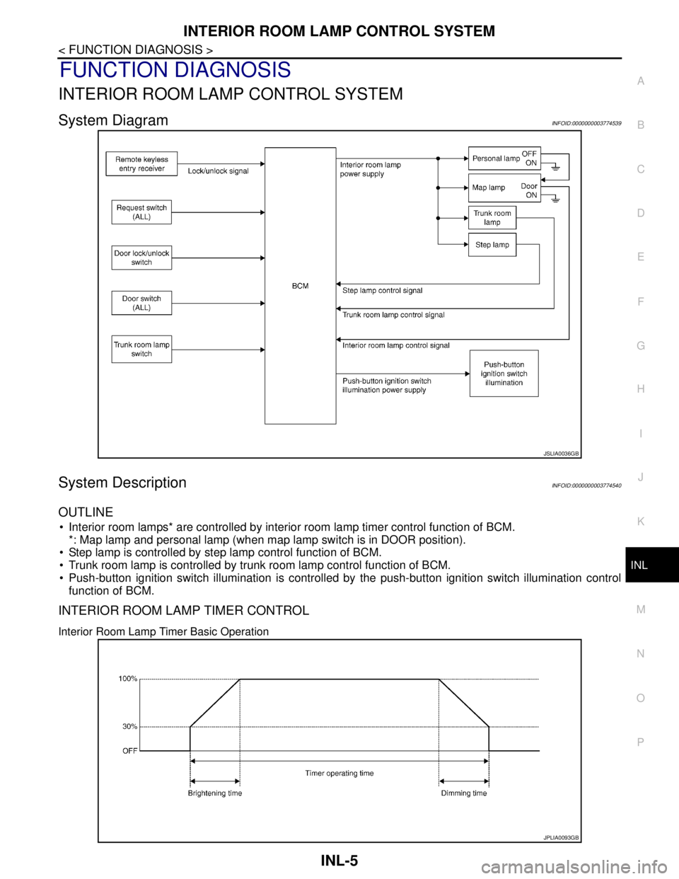
System DiagramINFOID:0000000003774539
System DescriptionINFOID:0000000003774540
OUTLINE
• Interior room lamps* are controlled by interior room lamp timer control function of BCM.
*: Map lamp and personal lamp (when map lamp switch is in DOOR position).
Step lamp is controlled by step lamp control function of BCM.
Trunk room lamp is controlled by trunk room lamp control function of BCM.
Push-button ignition switch illumination is controlled by the push-button ignition switch illumination control
function of BCM.
INTERIOR ROOM LAMP TIMER CONTROL
Interior Room Lamp Timer Basic Operation
JSLIA0036GB
JPLIA0093GB
Page 2885 of 5121

INL-6
< FUNCTION DIAGNOSIS >
INTERIOR ROOM LAMP CONTROL SYSTEM
The interior room lamp turns ON and OFF (gradual brightening and dimming) by the interior room timer.
BCM judges the vehicle condition with the following items. It activates the interior room timer.
- Ignition switch status
- Door switch signal (ALL)
- Door lock/unlock signal (Remote keyless entry receiver, each request switch, door lock/unlock switch)
NOTE:
Each function of interior room lamp timer can be set by CONSULT-III. Refer to INL-16, "
INT LAMP : CON-
SULT-III Function (BCM - INT LAMP)".
Interior Room Lamp ON Operation
BCM always turns the interior room lamp ON when any door opens.
BCM activates the interior room timer in any of the following conditions to turn the interior room lamp ON for
a period of time.
- Any door opens before all doors close.
- Ignition switch is turned ON → OFF.
- Any door unlock signal is detected when all doors close with ignition switch OFF.
NOTE:
Restart the timer if new condition is input during the timer operating time.
Interior Room Lamp OFF Operation
BCM stops the timer in any of the following conditions to turns the interior room lamp OFF.
The timer operating time is expired.
Ignition switch position is other than OFF with all doors close.
Any door lock operation is detected with all doors close.
STEP LAMP CONTROL
BCM controls the step lamp (ground-side) to turn ON with any door switch ON.
TRUNK ROOM LAMP CONTROL
BCM controls the trunk room lamp (ground-side) to turn ON with trunk room lamp switch ON.
PUSH-BUTTON IGNITION SWITCH ILLUMINATION CONTROL
Push-button Ignition Switch Illumination Basic Operation
BCM provides the power supply to turn the push-button ignition switch illumination ON.
Push-button Ignition Switch Illumination ON Operation
BCM turns the push-button ignition switch illumination ON in the following conditions.
Ignition switch ON
Any of the following conditions with ignition switch OFF
- Engine start permission is entered.
- Intelligent Key inserted into the key slot.
- Driver door is LOCK → UNLOCK.
- Driver door is open.
Push-button Ignition Switch Illumination OFF Operation
BCM turns the push-button ignition switch illumination OFF in any of the following conditions.
The push-button ignition switch illumination ON conditions do not satisfy.
All of the following conditions with ignition switch OFF
- The push-button ignition switch illumination ON conditions do not change (15 seconds after the ignition
switch OFF) or the driver door is UNLOCK → LOCK.