fog light NISSAN TEANA 2008 Manual PDF
[x] Cancel search | Manufacturer: NISSAN, Model Year: 2008, Model line: TEANA, Model: NISSAN TEANA 2008Pages: 5121, PDF Size: 69.03 MB
Page 3344 of 5121
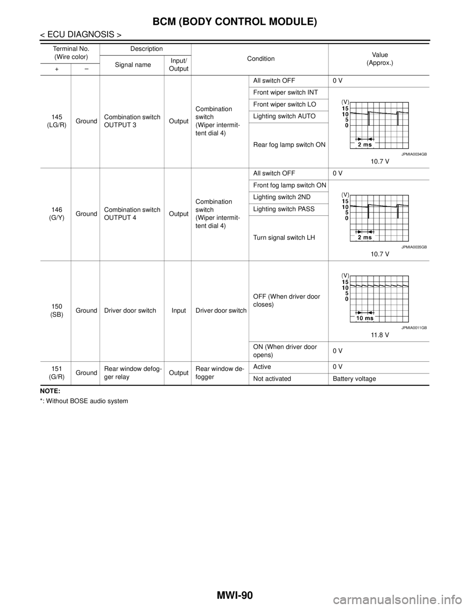
MWI-90
< ECU DIAGNOSIS >
BCM (BODY CONTROL MODULE)
NOTE:
*: Without BOSE audio system145
(LG/R)GroundCombination switch
OUTPUT 3OutputCombination
switch
(Wiper intermit-
tent dial 4)All switch OFF 0 V
Front wiper switch INT
10.7 V Front wiper switch LO
Lighting switch AUTO
Rear fog lamp switch ON
146
(G/Y)GroundCombination switch
OUTPUT 4OutputCombination
switch
(Wiper intermit-
tent dial 4)All switch OFF 0 V
Front fog lamp switch ON
10.7 V Lighting switch 2ND
Lighting switch PASS
Turn signal switch LH
150
(SB)Ground Driver door switch Input Driver door switchOFF (When driver door
closes)
11 . 8 V
ON (When driver door
opens)0 V
151
(G/R)GroundRear window defog-
ger relayOutputRear window de-
foggerActive 0 V
Not activated Battery voltage Te r m i n a l N o .
(Wire color)Description
ConditionVa l u e
(Approx.)
Signal nameInput/
Output +–
JPMIA0034GB
JPMIA0035GB
JPMIA0011GB
Page 3356 of 5121

MWI-102
< ECU DIAGNOSIS >
IPDM E/R (INTELLIGENT POWER DISTRIBUTION MODULE ENGINE ROOM)
IPDM E/R (INTELLIGENT POWER DISTRIBUTION MODULE ENGINE
ROOM)
Reference ValueINFOID:0000000003900501
VALUES ON THE DIAGNOSIS TOOL
Monitor Item Condition Value/Status
MOTOR FAN REQ Engine idle speedChanges depending on engine
coolant temperature, air conditioner
operation status, vehicle speed,
etc.1/2/3/4
AC COMP REQ Engine runningA/C switch OFF Off
A/C switch ON
(Compressor is operating)On
TAIL&CLR REQLighting switch OFF Off
Lighting switch 1ST, 2ND, HI or AUTO (Light is illuminated) On
HL LO REQLighting switch OFF Off
Lighting switch 2ND HI or AUTO (Light is illuminated) On
HL HI REQLighting switch OFF Off
Lighting switch HI On
FR FOG REQLighting switch 2ND or
AUTO (Light is illuminated)Front fog lamp switch OFF Off
Front fog lamp switch ON On
FR WIP REQ Ignition switch ONFront wiper switch OFF Stop
Front wiper switch INT 1LOW
Front wiper switch LO Low
Front wiper switch HI Hi
WIP AUTO STOP Ignition switch ONFront wiper stop position STOP P
Any position other than front wiper
stop positionACT P
WIP PROT Ignition switch ONFront wiper operates normally Off
Front wiper stops at fail-safe opera-
tionBLOCK
IGN RLY1 -REQIgnition switch OFF or ACC Off
Ignition switch ON On
IGN RLYIgnition switch OFF or ACC Off
Ignition switch ON On
PUSH SWRelease the push-button ignition switch Off
Press the push-button ignition switch On
INTER/NP SW Ignition switch ONSelector lever in any position other
than P or NOff
Selector lever in P or N position On
ST RLY CONTIgnition switch ON Off
At engine cranking On
IHBT RLY -REQIgnition switch ON Off
At engine cranking On
Page 3362 of 5121

MWI-108
< ECU DIAGNOSIS >
IPDM E/R (INTELLIGENT POWER DISTRIBUTION MODULE ENGINE ROOM)
75
(P/L)Ground Oil pressure switch InputIgnition
switch ONEngine stopped 0 V
Engine running Battery voltage
76
(SB)GroundPower generation com-
mand signalOutputIgnition switch ON
6.3 V
40% is set on “ACTIVE TEST”, “AL-
TERNATOR DUTY” of “ENGINE”
3.8 V
80% is set on “ACTIVE TEST”, “AL-
TERNATOR DUTY” of “ENGINE”
1.4 V
77
(GR)Ground Fuel pump relay control Output Approximately 1 second after turning
the ignition switch ON
Engine running0 - 1.5 V
Approximately 1 second or more after
turning the ignition switch ONBattery voltage
80
(B/W)Ground Starter motor Output At engine cranking Battery voltage
83
(Y)Ground Headlamp LO (RH) OutputIgnition
switch ONLighting switch OFF 0 V
Lighting switch 2ND Battery voltage
84
(SB)Ground Headlamp LO (LH) OutputIgnition
switch ONLighting switch OFF 0 V
Lighting switch 2ND Battery voltage
86
(L)Ground Front fog lamp (RH) OutputLighting
switch
2ND Front fog lamp switch
ON
Daytime running light
activated (Only for Can-
ada)Battery voltage
Front fog lamp switch OFF 0 V
87
(R)Ground Front fog lamp (LH) OutputLighting
switch
2ND Front fog lamp switch
ON
Daytime running light
activated (Only for Can-
ada)Battery voltage
Front fog lamp switch OFF 0 V Te r m i n a l N o .
(Wire color)Description
ConditionVa l u e
(Approx.)
Signal nameInput/
Output +−
JPMIA0001GB
JPMIA0002GB
JPMIA0003GB
Page 3396 of 5121

PCS
RELAY CONTROL SYSTEM
PCS-5
< FUNCTION DIAGNOSIS >[IPDM E/R]
C
D
E
F
G
H
I
J
K
L B A
O
P N
NOTE:
BCM controls the starter relay.Control relay Input/output Transmit unit Control part Reference page
• Headlamp low relay
Headlamp high relay Low beam request signal
High beam request signalBCM (CAN) Headlamp low
Headlamp highEXL-11
(Xenon headlamp)
EXL-200
(Halogen headlamp)
Front fog lamp relay Front fog light request signal BCM (CAN) Front fog lampEXL-17
(Xenon headlamp)
EXL-204
(Halogen headlamp)
Tail lamp relay Position light request signal BCM (CAN) Parking lamp
Side marker lamp
License plate lamp
Tail lampEXL-21
(Xenon headlamp)
EXL-208
(Halogen headlamp)
IlluminationsINL-12
Front wiper relay
Front wiper high relayFront wiper request signal BCM (CAN)
Front wiperWW-5
Front wiper auto stop signal Front wiper motor
Horn relay Theft warning horn request
signal
Horn reminder signalBCM (CAN) Horn (low)
Horn (high)SEC-17
Starter relayNOTE
Starter control relayStarter control relay signal BCM (CAN)
Starter motorSEC-104SEC-102
Steering lock unit condition
signalSteering lock unit
Starter relay control signal TCM
Steering lock relaySteering lock relay signal BCM (CAN)
Steering lock unitSEC-69
Steering lock unit condition
signalSteering lock unit
Control device (Detention
switch) signalControl device (Detention
switch)
A/C relayA/C compressor request sig-
nalECM (CAN)A/C compressor
(magnet clutch)HAC-36
(Without 7-inch dis-
play)
HAC-154
(With 7-inch display)
Cooling fan relay-1
Cooling fan relay-2
Cooling fan relay-3Cooling fan speed request sig-
nalECM (CAN) Cooling fan motor-
1
Cooling fan motor-
2EC-60
Headlamp washer relayHeadlamp washer request
signalBCM (CAN) Headlamp washerWW-10
Ignition relayIgnition switch ON signal BCM (CAN)
Ignition relay PCS-17Vehicle speed signal Combination meter (CAN)
Push-button ignition switch
signalPush-button ignition
switch
Page 3404 of 5121

PCS
DIAGNOSIS SYSTEM (IPDM E/R)
PCS-13
< FUNCTION DIAGNOSIS >[IPDM E/R]
C
D
E
F
G
H
I
J
K
L B A
O
P N
CONSULT-III Function (IPDM E/R)INFOID:0000000003773268
APPLICATION ITEM
CONSULT-III performs the following functions via CAN communication with IPDM E/R.
SELF DIAGNOSTIC RESULT
Refer to PCS-33, "DTCIndex".
DATA MONITOR
Monitor item
Cooling fan does not operatePerform auto active test.
Does the cooling fan operate?YES ECM signal input circuit
CAN communication signal
between ECM and IPDM E/
R
NO Harness or connector be-
tween IPDM E/R and cool-
ing fan motor
Harness or connector be-
tween IPDM E/R and cool-
ing fan relay
Cooling fan motor
Cooling fan relay
IPDM E/R Symptom Inspection contents Possible cause
Diagnosis mode Description
Ecu Identification Allows confirmation of IPDM E/R part number.
Self Diagnostic Result Displays the diagnosis results judged by IPDM E/R.
Data Monitor Displays the real-time input/output data from IPDM E/R input/output data.
Active Test IPDM E/R can provide a drive signal to electronic components to check their operations.
CAN Diag Support Monitor The results of transmit/receive diagnosis of CAN communication can be read.
Monitor Item
[Unit]MAIN SIG-
NALSDescription
MOTOR FAN REQ
[1/2/3/4]×Displays the value of the cooling fan speed request signal received from ECM via
CAN communication.
AC COMP REQ
[Off/On]×Displays the status of the A/C compressor request signal received from ECM via
CAN communication.
TAIL&CLR REQ
[Off/On]×Displays the status of the position light request signal received from BCM via CAN
communication.
HL LO REQ
[Off/On]×Displays the status of the low beam request signal received from BCM via CAN
communication.
HL HI REQ
[Off/On]×Displays the status of the high beam request signal received from BCM via CAN
communication.
FR FOG REQ
[Off/On]×Displays the status of the front fog light request signal received from BCM via
CAN communication.
FR WIP REQ
[Stop/1LOW/Low/Hi]×Displays the status of the front wiper request signal received from BCM via CAN
communication.
WIP AUTO STOP
[STOP P/ACT P]×Displays the status of the front wiper auto stop signal judged by IPDM E/R.
WIP PROT
[Off/BLOCK]×Displays the status of the front wiper fail-safe operation judged by IPDM E/R.
IGN RLY1 -REQ
[Off/On]Displays the status of the ignition switch ON signal received from BCM via CAN
communication.
Page 3411 of 5121

PCS-20
< ECU DIAGNOSIS >[IPDM E/R]
IPDM E/R (INTELLIGENT POWER DISTRIBUTION MODULE ENGINE ROOM)
ECU DIAGNOSIS
IPDM E/R (INTELLIGENT POWER DISTRIBUTION MODULE ENGINE
ROOM)
Reference ValueINFOID:0000000003773279
VALUES ON THE DIAGNOSIS TOOL
Monitor Item Condition Value/Status
MOTOR FAN REQ Engine idle speedChanges depending on engine
coolant temperature, air conditioner
operation status, vehicle speed,
etc.1/2/3/4
AC COMP REQ Engine runningA/C switch OFF Off
A/C switch ON
(Compressor is operating)On
TAIL&CLR REQLighting switch OFF Off
Lighting switch 1ST, 2ND, HI or AUTO (Light is illuminated) On
HL LO REQLighting switch OFF Off
Lighting switch 2ND HI or AUTO (Light is illuminated) On
HL HI REQLighting switch OFF Off
Lighting switch HI On
FR FOG REQLighting switch 2ND or
AUTO (Light is illuminated)Front fog lamp switch OFF Off
Front fog lamp switch ON On
FR WIP REQ Ignition switch ONFront wiper switch OFF Stop
Front wiper switch INT 1LOW
Front wiper switch LO Low
Front wiper switch HI Hi
WIP AUTO STOP Ignition switch ONFront wiper stop position STOP P
Any position other than front wiper
stop positionACT P
WIP PROT Ignition switch ONFront wiper operates normally Off
Front wiper stops at fail-safe opera-
tionBLOCK
IGN RLY1 -REQIgnition switch OFF or ACC Off
Ignition switch ON On
IGN RLYIgnition switch OFF or ACC Off
Ignition switch ON On
PUSH SWRelease the push-button ignition switch Off
Press the push-button ignition switch On
INTER/NP SW Ignition switch ONSelector lever in any position other
than P or NOff
Selector lever in P or N position On
ST RLY CONTIgnition switch ON Off
At engine cranking On
IHBT RLY -REQIgnition switch ON Off
At engine cranking On
Page 3417 of 5121

PCS-26
< ECU DIAGNOSIS >[IPDM E/R]
IPDM E/R (INTELLIGENT POWER DISTRIBUTION MODULE ENGINE ROOM)
75
(P/L)Ground Oil pressure switch InputIgnition
switch ONEngine stopped 0 V
Engine running Battery voltage
76
(SB)GroundPower generation com-
mand signalOutputIgnition switch ON
6.3 V
40% is set on “ACTIVE TEST”, “AL-
TERNATOR DUTY” of “ENGINE”
3.8 V
80% is set on “ACTIVE TEST”, “AL-
TERNATOR DUTY” of “ENGINE”
1.4 V
77
(GR)Ground Fuel pump relay control Output Approximately 1 second after turning
the ignition switch ON
Engine running0 - 1.5 V
Approximately 1 second or more after
turning the ignition switch ONBattery voltage
80
(B/W)Ground Starter motor Output At engine cranking Battery voltage
83
(Y)Ground Headlamp LO (RH) OutputIgnition
switch ONLighting switch OFF 0 V
Lighting switch 2ND Battery voltage
84
(SB)Ground Headlamp LO (LH) OutputIgnition
switch ONLighting switch OFF 0 V
Lighting switch 2ND Battery voltage
86
(L)Ground Front fog lamp (RH) OutputLighting
switch
2ND Front fog lamp switch
ON
Daytime running light
activated (Only for Can-
ada)Battery voltage
Front fog lamp switch OFF 0 V
87
(R)Ground Front fog lamp (LH) OutputLighting
switch
2ND Front fog lamp switch
ON
Daytime running light
activated (Only for Can-
ada)Battery voltage
Front fog lamp switch OFF 0 V Te r m i n a l N o .
(Wire color)Description
ConditionVa l u e
(Approx.)
Signal nameInput/
Output +−
JPMIA0001GB
JPMIA0002GB
JPMIA0003GB
Page 3464 of 5121

PCS
BCM (BODY CONTROL MODULE)
PCS-73
< ECU DIAGNOSIS >[POWER DISTRIBUTION SYSTEM]
C
D
E
F
G
H
I
J
K
L B A
O
P N
ECU DIAGNOSIS
BCM (BODY CONTROL MODULE)
Reference ValueINFOID:0000000003880874
VALUES ON THE DIAGNOSIS TOOL
CONSULT-III MONITOR ITEM
Monitor Item Condition Value/Status
FR WIPER HIOther than front wiper switch HI Off
Front wiper switch HI On
FR WIPER LOWOther than front wiper switch LO Off
Front wiper switch LO On
FR WASHER SWFront washer switch OFF Off
Front washer switch ON On
FR WIPER INTOther than front wiper switch INT Off
Front wiper switch INT On
FR WIPER STOPFront wiper is not in STOP position Off
Front wiper is in STOP position On
INT VOLUME Wiper intermittent dial is in a dial position 1 - 7 Wiper intermittent dial position
TURN SIGNAL ROther than turn signal switch RH Off
Turn signal switch RH On
TURN SIGNAL LOther than turn signal switch LH Off
Turn signal switch LH On
TAIL LAMP SWOther than lighting switch 1ST and 2ND Off
Lighting switch 1ST or 2ND On
HI BEAM SWOther than lighting switch HI Off
Lighting switch HI On
HEAD LAMP SW 1Other than lighting switch 2ND Off
Lighting switch 2ND On
HEAD LAMP SW 2Other than lighting switch 2ND Off
Lighting switch 2ND On
PA S S I N G S WOther than lighting switch PASS Off
Lighting switch PASS On
AUTO LIGHT SWOther than lighting switch AUTO Off
Lighting switch AUTO On
FR FOG SWFront fog lamp switch OFF Off
Front fog lamp switch ON On
RR FOG SWRear fog lamp switch OFF Off
Rear fog lamp switch ON On
DOOR SW-DRDriver door closed Off
Driver door opened On
DOOR SW-ASPassenger door closed Off
Passenger door opened On
DOOR SW-RRRear RH door closed Off
Rear RH door opened On
Page 3486 of 5121

PCS
BCM (BODY CONTROL MODULE)
PCS-95
< ECU DIAGNOSIS >[POWER DISTRIBUTION SYSTEM]
C
D
E
F
G
H
I
J
K
L B A
O
P N
NOTE:
*: Without BOSE audio system145
(LG/R)GroundCombination switch
OUTPUT 3OutputCombination
switch
(Wiper intermit-
tent dial 4)All switch OFF 0 V
Front wiper switch INT
10.7 V Front wiper switch LO
Lighting switch AUTO
Rear fog lamp switch ON
146
(G/Y)GroundCombination switch
OUTPUT 4OutputCombination
switch
(Wiper intermit-
tent dial 4)All switch OFF 0 V
Front fog lamp switch ON
10.7 V Lighting switch 2ND
Lighting switch PASS
Turn signal switch LH
150
(SB)Ground Driver door switch Input Driver door switchOFF (When driver door
closes)
11.8 V
ON (When driver door
opens)0 V
151
(G/R)GroundRear window defog-
ger relayOutputRear window de-
foggerActive 0 V
Not activated Battery voltage Te r m i n a l N o .
(Wire color)Description
ConditionVa l u e
(Approx.)
Signal nameInput/
Output +–
JPMIA0034GB
JPMIA0035GB
JPMIA0011GB
Page 3498 of 5121

PCS
IPDM E/R (INTELLIGENT POWER DISTRIBUTION MODULE ENGINE ROOM)
PCS-107
< ECU DIAGNOSIS >[POWER DISTRIBUTION SYSTEM]
C
D
E
F
G
H
I
J
K
L B A
O
P N
IPDM E/R (INTELLIGENT POWER DISTRIBUTION MODULE ENGINE
ROOM)
Reference ValueINFOID:0000000003880879
VALUES ON THE DIAGNOSIS TOOL
Monitor Item Condition Value/Status
MOTOR FAN REQ Engine idle speedChanges depending on engine
coolant temperature, air conditioner
operation status, vehicle speed,
etc.1/2/3/4
AC COMP REQ Engine runningA/C switch OFF Off
A/C switch ON
(Compressor is operating)On
TA I L & C L R R E QLighting switch OFF Off
Lighting switch 1ST, 2ND, HI or AUTO (Light is illuminated) On
HL LO REQLighting switch OFF Off
Lighting switch 2ND HI or AUTO (Light is illuminated) On
HL HI REQLighting switch OFF Off
Lighting switch HI On
FR FOG REQLighting switch 2ND or
AUTO (Light is illuminated)Front fog lamp switch OFF Off
Front fog lamp switch ON On
FR WIP REQ Ignition switch ONFront wiper switch OFF Stop
Front wiper switch INT 1LOW
Front wiper switch LO Low
Front wiper switch HI Hi
WIP AUTO STOP Ignition switch ONFront wiper stop position STOP P
Any position other than front wiper
stop positionACT P
WIP PROT Ignition switch ONFront wiper operates normally Off
Front wiper stops at fail-safe opera-
tionBLOCK
IGN RLY1 -REQIgnition switch OFF or ACC Off
Ignition switch ON On
IGN RLYIgnition switch OFF or ACC Off
Ignition switch ON On
PUSH SWRelease the push-button ignition switch Off
Press the push-button ignition switch On
INTER/NP SW Ignition switch ONSelector lever in any position other
than P or NOff
Selector lever in P or N position On
ST RLY CONTIgnition switch ON Off
At engine cranking On
IHBT RLY -REQIgnition switch ON Off
At engine cranking On