key battery NISSAN TEANA 2008 Service Manual
[x] Cancel search | Manufacturer: NISSAN, Model Year: 2008, Model line: TEANA, Model: NISSAN TEANA 2008Pages: 5121, PDF Size: 69.03 MB
Page 7 of 5121

ADP-1
BODY INTERIOR
C
D
E
F
G
H
I
K
L
M
SECTION ADP
A
B
ADP
N
O
P
CONTENTS
AUTOMATIC DRIVE POSITIONER
BASIC INSPECTION ....................................4
DIAGNOSIS AND REPAIR WORKFLOW ..........4
Work Flow .................................................................4
INSPECTION AND ADJUSTMENT .....................7
ADDITIONAL SERVICE WHEN REMOVING BAT-
TERY NEGATIVE TERMINAL .....................................
7
ADDITIONAL SERVICE WHEN REMOVING
BATTERY NEGATIVE TERMINAL : Description ......
7
ADDITIONAL SERVICE WHEN REMOVING
BATTERY NEGATIVE TERMINAL : Special Re-
pair Requirement .......................................................
7
ADDITIONAL SERVICE WHEN REPLACING
CONTROL UNIT ..........................................................
7
ADDITIONAL SERVICE WHEN REPLACING
CONTROL UNIT : Description ..................................
7
ADDITIONAL SERVICE WHEN REPLACING
CONTROL UNIT : Special Repair Requirement .......
7
SYSTEM INITIALIZATION ..........................................8
SYSTEM INITIALIZATION : Description ...................8
SYSTEM INITIALIZATION : Special Repair Re-
quirement ..................................................................
8
MEMORY STORING ....................................................8
MEMORY STORING : Description ............................8
MEMORY STORING : Special Repair Require-
ment ..........................................................................
9
SYSTEM SETTING ......................................................9
SYSTEM SETTING : Description ..............................9
SYSTEM SETTING : Special Repair Requirement
....
10
FUNCTION DIAGNOSIS ..............................12
AUTOMATIC DRIVE POSITIONER SYSTEM ....12
AUTOMATIC DRIVE POSITIONER SYSTEM ...........12
AUTOMATIC DRIVE POSITIONER SYSTEM :
System Diagram ......................................................
12
AUTOMATIC DRIVE POSITIONER SYSTEM :
System Description ..................................................
12
AUTOMATIC DRIVE POSITIONER SYSTEM :
Component Parts Location ......................................
14
AUTOMATIC DRIVE POSITIONER SYSTEM :
Component Description ..........................................
15
MANUAL FUNCTION ................................................16
MANUAL FUNCTION : System Diagram ................16
MANUAL FUNCTION : System Description ............16
MANUAL FUNCTION : Component Parts Loca-
tion ...........................................................................
17
MANUAL FUNCTION : Component Description .....18
MEMORY FUNCTION ................................................18
MEMORY FUNCTION : System Diagram ...............19
MEMORY FUNCTION : System Description ...........19
MEMORY FUNCTION : Component Parts Loca-
tion ...........................................................................
21
MEMORY FUNCTION : Component Description ....22
EXIT ASSIST FUNCTION ..........................................22
EXIT ASSIST FUNCTION : System Diagram ..........23
EXIT ASSIST FUNCTION : System Description .....23
EXIT ASSIST FUNCTION : Component Parts Lo-
cation .......................................................................
25
EXIT ASSIST FUNCTION :
Component Description ..........................................
26
ENTRY ASSIST FUNCTION ......................................26
ENTRY ASSIST FUNCTION : System Diagram .....27
ENTRY ASSIST FUNCTION : System Description
....
27
ENTRY ASSIST FUNCTION : Component Parts
Location ...................................................................
29
ENTRY ASSIST FUNCTION :
Component Description ..........................................
30
INTELLIGENT KEY INTERLOCK FUNCTION ..........30
Page 13 of 5121
INSPECTION AND ADJUSTMENT
ADP-7
< BASIC INSPECTION >
C
D
E
F
G
H
I
K
L
MA
B
ADP
N
O
P
INSPECTION AND ADJUSTMENT
ADDITIONAL SERVICE WHEN REMOVING BATTERY NEGATIVE TERMINAL
ADDITIONAL SERVICE WHEN REMOVING BATTERY NEGATIVE TERMINAL : De-
scription
INFOID:0000000003759058
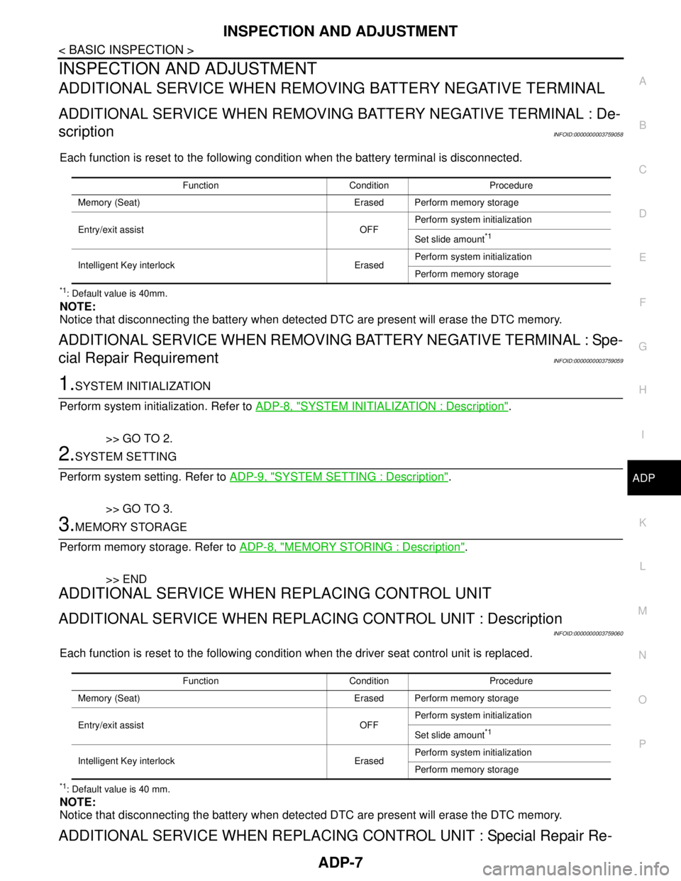
Each function is reset to the following condition when the battery terminal is disconnected.
*1: Default value is 40mm.
NOTE:
Notice that disconnecting the battery when detected DTC are present will erase the DTC memory.
ADDITIONAL SERVICE WHEN REMOVING BATTERY NEGATIVE TERMINAL : Spe-
cial Repair Requirement
INFOID:0000000003759059
1.SYSTEM INITIALIZATION
Perform system initialization. Refer to ADP-8, "
SYSTEM INITIALIZATION : Description".
>> GO TO 2.
2.SYSTEM SETTING
Perform system setting. Refer to ADP-9, "
SYSTEM SETTING : Description".
>> GO TO 3.
3.MEMORY STORAGE
Perform memory storage. Refer to ADP-8, "
MEMORY STORING : Description".
>> END
ADDITIONAL SERVICE WHEN REPLACING CONTROL UNIT
ADDITIONAL SERVICE WHEN REPLACING CONTROL UNIT : Description
INFOID:0000000003759060
Each function is reset to the following condition when the driver seat control unit is replaced.
*1: Default value is 40 mm.
NOTE:
Notice that disconnecting the battery when detected DTC are present will erase the DTC memory.
ADDITIONAL SERVICE WHEN REPLACING CONTROL UNIT : Special Repair Re-
Function Condition Procedure
Memory (Seat) Erased Perform memory storage
Entry/exit assist OFFPerform system initialization
Set slide amount
*1
Intelligent Key interlock ErasedPerform system initialization
Perform memory storage
Function Condition Procedure
Memory (Seat) Erased Perform memory storage
Entry/exit assist OFFPerform system initialization
Set slide amount
*1
Intelligent Key interlock ErasedPerform system initialization
Perform memory storage
Page 14 of 5121

ADP-8
< BASIC INSPECTION >
INSPECTION AND ADJUSTMENT
quirement
INFOID:0000000003759061
1.SYSTEM INITIALIZATION
Perform system initialization. Refer to ADP-8, "
SYSTEM INITIALIZATION : Description".
>> GO TO 2.
2.SYSTEM SETTING
Perform system setting. Refer to ADP-9, "
SYSTEM SETTING : Description".
>> GO TO 3.
3.MEMORY STORAGE
Perform memory storage. Refer to ADP-8, "
MEMORY STORING : Description".
>> END
SYSTEM INITIALIZATION
SYSTEM INITIALIZATION : DescriptionINFOID:0000000003759062
Always perform the initialization when the battery terminal is disconnected or the driver seat control unit is
replaced.
The entry/exit assist function will not operate normally unless initialization is performed.
SYSTEM INITIALIZATION : Special Repair RequirementINFOID:0000000003759063
INITIALIZATION PROCEDURE
1. CHOOSE METHOD
There are two initialization methods.
Which method do you use?
With door switch>>GO TO 2.
With vehicle speed>>GO TO 4.
2. STEP A-1
Turn ignition switch from the ACC to the OFF position.
>> GO TO 3.
3. STEP A-2
Driver door switch is ON (open) → OFF (close) → ON (open).
>> END
4. STEP B-1
Drive the vehicle at more than 25 km/h (16 MPH).
>> END
MEMORY STORING
MEMORY STORING : DescriptionINFOID:0000000003759064
Always perform memory storage when the battery terminal is disconnected or the driver seat control unit is
replaced. The memory function and Intelligent Key interlock function will not operate normally unless memory
storage is performed.
Page 15 of 5121

INSPECTION AND ADJUSTMENT
ADP-9
< BASIC INSPECTION >
C
D
E
F
G
H
I
K
L
MA
B
ADP
N
O
P
MEMORY STORING : Special Repair RequirementINFOID:0000000003759065
Memory Storage Procedure
Two positions for the driver seat can be stored for memory operation by the following procedure.
1.STEP 1
Shift selector lever to the P position.
>> GO TO 2.
2.STEP 2
Turn ignition switch ON.
>> GO TO 3.
3.STEP 3
Adjust driver seat position manually.
>> GO TO 4.
4.STEP 4
1. Push set switch.
NOTE:
Memory indicator for which driver seat position is already retained in memory is illuminated for 5 sec-
onds.
Memory indicator for which driver seat position is not retained in memory is illuminated for 0.5 seconds.
2. Push the memory switch (1 or 2) for at least 1 second within 5 seconds after pushing the set switch.
NOTE:
When entering driver seat positions into blank memory, memory indicator turns ON for 5 seconds.
When changing driver seat positions, memory indicator turns OFF for 0.5 seconds, then turns ON for 5
seconds.
NOTE:
If memory is stored in the same memory switch, the previous memory will be deleted.
Do you need to link Intelligent Keys?
YES >> GO TO 5.
NO >> END
5.STEP 6
Push the Intelligent Key unlock button within 5 seconds after pushing memory switch (while the memory indi-
cator is ON).
>> GO TO 6.
6.STEP 7
Confirm the operation of each part with memory operation and Intelligent Key interlock operation.
>> END
SYSTEM SETTING
SYSTEM SETTING : DescriptionINFOID:0000000003759066
The settings of the automatic driving positioner system can be changed, using CONSULT-III, the display unit
in the center of the instrument panel and the set switch. Always check the settings before and after discon-
necting the battery terminal or replacing driver seat control unit.
Setting Change
Page 42 of 5121

ADP-36
< FUNCTION DIAGNOSIS >
DIAGNOSIS SYSTEM (DRIVER SEAT CONTROL UNIT)
ACTIVE TEST
CAUTION:
When driving vehicle never perform active test.
WORK SUPPORT
SLIDE PULSE — –×Value (32768) when battery connections are standard. If it
moves backward, the value increases. If it moves forward,
the value decreases
RECLN PULSE — –×Value (32768) when battery connections are standard. If it
moves backward, the value increases. If it moves forward,
the value decreases
LIFT FR PULSE — –×Value (32768) when battery connections are standard. If it
moves DOWN, the value increases. If it moves UP, the val-
ue decreases
LIFT RR PULSE — –×Value (32768) when battery connections are standard. If it
moves DOWN, the value increases. If it moves UP, the val-
ue decreases
VEHICLE SPEED —××Display the vehicle speed signal received from combination
meter by numerical value [km/h]
P RANG SW CAN “ON/OFF”××ON/OFF status judged from the P range switch signal
R RANGE (CAN) “ON/OFF”××ON/OFF status judged from the R range switch signal
DOOR SW–FL “ON/OFF”××ON/OFF status judged from the door switch (front driver
side) signal
DOOR SW–FR “ON/OFF”××ON/OFF status judged from the door switch (front passen-
ger side) signal
IGN ON SW “ON/OFF”××ON/OFF status judged from the ignition switch signal
ACC ON SW “ON/OFF”××ON/OFF status judged from the ACC switch signal
KEY ON SW “ON/OFF”××ON/OFF status judged from the key on switch signal
KEYLESS ID —××Key ID status judged from the key ID signal
KYLS DR UNLK “ON/OFF”××ON/OFF status judged from the driver side door unlock ac-
tuator output switch signal
VHCL SPEED (ABS) “ON/OFF”××ON/OFF status judged from vehicle speed signal
HANDLE “RHD/LHD”××RHD/LHD status judged from handle position signal
TRANSMISSION“AT or CVT/
MT”××AT or CVT/MT status judged from transmission
STEERING STATUS“LOCK/UN-
LOCK”××LOCK/UNLOCK status judged from steering lock unit Monitor Item UnitMain
SignalsSelection
From
MenuContents
Test item Description
SEAT SLIDE Activates/deactivates the sliding motor
SEAT RECLINING Activates/deactivates the reclining motor
SEAT LIFTER FR Activates/deactivates the lifting motor (front)
SEAT LIFTER RR Activates/deactivates the lifting motor (rear)
MEMORY SW INDCTR Turns ON/OFF the memory indicator
Work item Content Item
SEAT SLIDE VOLUME SETThe amount of seat sliding for entry/exit assist can be selected
from 3 items.40 mm
80 mm
150 mm
Page 92 of 5121
ADP-86
< COMPONENT DIAGNOSIS >
BCM (BODY CONTROL MODULE)
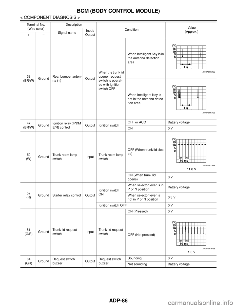
39
(BR/W)GroundRear bumper anten-
na (+)OutputWhen the trunk lid
opener request
switch is operat-
ed with ignition
switch OFFWhen Intelligent Key is in
the antenna detection
area
When Intelligent Key is
not in the antenna detec-
tion area
47
(BR/W)GroundIgnition relay (IPDM
E/R) controlOutput Ignition switchOFF or ACC Battery voltage
ON 0 V
50
(W)GroundTrunk room lamp
switchInputTrunk room lamp
switchOFF (When trunk lid clos-
es)
11 . 8 V
ON (When trunk lid
opens)0 V
52
(R)Ground Starter relay control OutputIgnition switch
ONWhen selector lever is in
P or N positionBattery voltage
When selector lever is
not in P or N position0.3 V
Ignition switch OFF 0 V
61
(G/R)GroundTrunk lid request
switchInputTrunk lid request
switchON (Pressed) 0 V
OFF (Not pressed)
1.0 V
64
(GR)GroundRequest switch
buzzerOutputRequest switch
buzzerSounding 0 V
Not sounding Battery voltage Te r m i n a l N o .
(Wire color)Description
ConditionVa l u e
(Approx.)
Signal nameInput/
Output +–
JMKIA0062GB
JMKIA0063GB
JPMIA0011GB
JPMIA0016GB
Page 96 of 5121
ADP-90
< COMPONENT DIAGNOSIS >
BCM (BODY CONTROL MODULE)
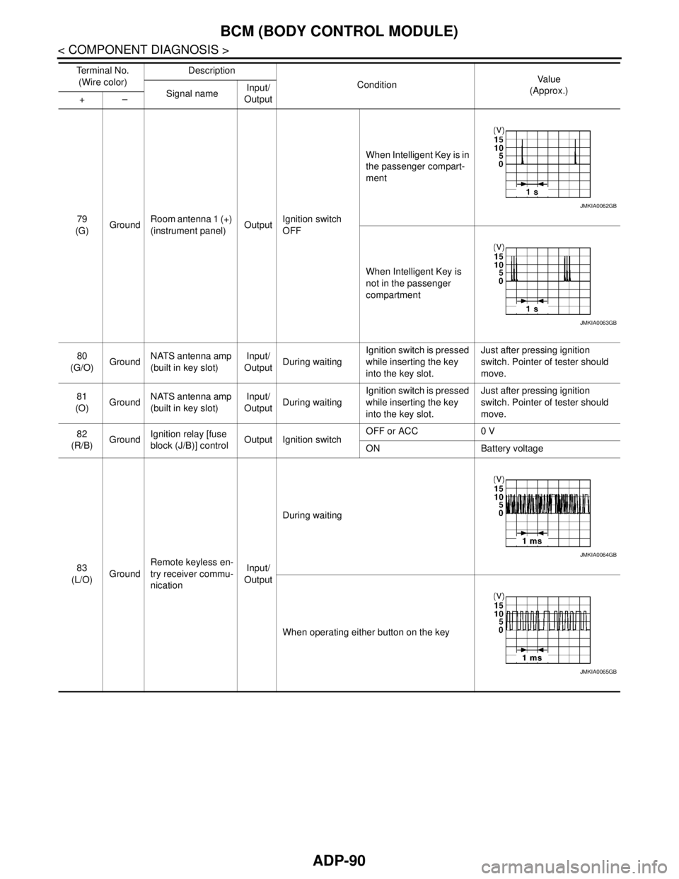
79
(G)GroundRoom antenna 1 (+)
(instrument panel)OutputIgnition switch
OFFWhen Intelligent Key is in
the passenger compart-
ment
When Intelligent Key is
not in the passenger
compartment
80
(G/O)GroundNATS antenna amp
(built in key slot)Input/
OutputDuring waitingIgnition switch is pressed
while inserting the key
into the key slot.Just after pressing ignition
switch. Pointer of tester should
move.
81
(O)GroundNATS antenna amp
(built in key slot)Input/
OutputDuring waitingIgnition switch is pressed
while inserting the key
into the key slot.Just after pressing ignition
switch. Pointer of tester should
move.
82
(R/B)GroundIgnition relay [fuse
block (J/B)] controlOutput Ignition switchOFF or ACC 0 V
ON Battery voltage
83
(L/O)GroundRemote keyless en-
try receiver commu-
nicationInput/
OutputDuring waiting
When operating either button on the key Te r m i n a l N o .
(Wire color)Description
ConditionVa l u e
(Approx.)
Signal nameInput/
Output +–
JMKIA0062GB
JMKIA0063GB
JMKIA0064GB
JMKIA0065GB
Page 98 of 5121
ADP-92
< COMPONENT DIAGNOSIS >
BCM (BODY CONTROL MODULE)
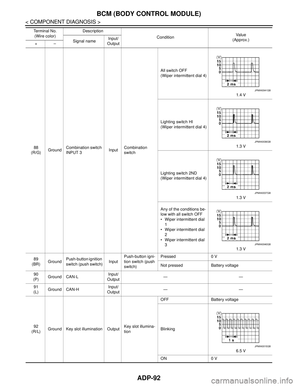
88
(R/G)GroundCombination switch
INPUT 3InputCombination
switchAll switch OFF
(Wiper intermittent dial 4)
1.4 V
Lighting switch HI
(Wiper intermittent dial 4)
1.3 V
Lighting switch 2ND
(Wiper intermittent dial 4)
1.3 V
Any of the conditions be-
low with all switch OFF
Wiper intermittent dial
1
Wiper intermittent dial
2
Wiper intermittent dial
3
1.3 V
89
(BR)GroundPush-button ignition
switch (push switch)InputPush-button igni-
tion switch (push
switch)Pressed 0 V
Not pressed Battery voltage
90
(P)Ground CAN-LInput/
Output——
91
(L)Ground CAN-HInput/
Output——
92
(R/L)Ground Key slot illumination OutputKey slot illumina-
tionOFF Battery voltage
Blinking
6.5 V
ON 0 V Te r m i n a l N o .
(Wire color)Description
ConditionVa l u e
(Approx.)
Signal nameInput/
Output +–
JPMIA0041GB
JPMIA0036GB
JPMIA0037GB
JPMIA0040GB
JPMIA0015GB
Page 99 of 5121
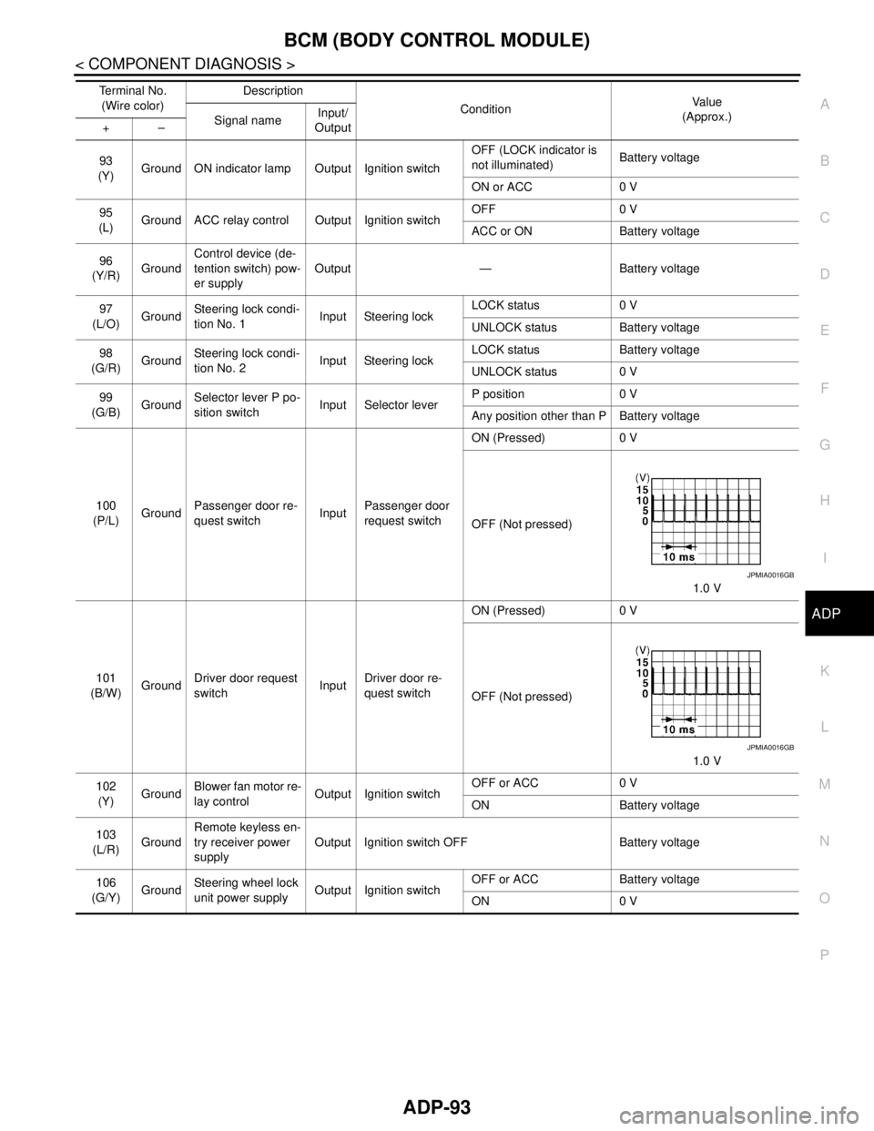
BCM (BODY CONTROL MODULE)
ADP-93
< COMPONENT DIAGNOSIS >
C
D
E
F
G
H
I
K
L
MA
B
ADP
N
O
P
93
(Y)Ground ON indicator lamp Output Ignition switchOFF (LOCK indicator is
not illuminated)Battery voltage
ON or ACC 0 V
95
(L)Ground ACC relay control Output Ignition switchOFF 0 V
ACC or ON Battery voltage
96
(Y/R)GroundControl device (de-
tention switch) pow-
er supplyOutput — Battery voltage
97
(L/O)GroundSteering lock condi-
tion No. 1Input Steering lockLOCK status 0 V
UNLOCK status Battery voltage
98
(G/R)GroundSteering lock condi-
tion No. 2Input Steering lockLOCK status Battery voltage
UNLOCK status 0 V
99
(G/B)GroundSelector lever P po-
sition switchInput Selector leverP position 0 V
Any position other than P Battery voltage
100
(P/L)GroundPassenger door re-
quest switchInputPassenger door
request switchON (Pressed) 0 V
OFF (Not pressed)
1.0 V
101
(B/W)GroundDriver door request
switchInputDriver door re-
quest switchON (Pressed) 0 V
OFF (Not pressed)
1.0 V
102
(Y)GroundBlower fan motor re-
lay controlOutput Ignition switchOFF or ACC 0 V
ON Battery voltage
103
(L/R)GroundRemote keyless en-
try receiver power
supplyOutput Ignition switch OFF Battery voltage
106
(G/Y)GroundSteering wheel lock
unit power supplyOutput Ignition switchOFF or ACC Battery voltage
ON 0 V Te r m i n a l N o .
(Wire color)Description
ConditionVa l u e
(Approx.)
Signal nameInput/
Output +–
JPMIA0016GB
JPMIA0016GB
Page 103 of 5121

BCM (BODY CONTROL MODULE)
ADP-97
< COMPONENT DIAGNOSIS >
C
D
E
F
G
H
I
K
L
MA
B
ADP
N
O
P
111
(L/Y)GroundSteering lock unit
communicationInput/
OutputSteering lockLOCK status Battery voltage
LOCK or UNLOCK
For 15 seconds after UN-
LOCKBattery voltage
15 seconds or later after
UNLOCK0 V
11 3
(P/B)Ground Optical sensor InputIgnition switch
ONWhen bright outside of
the vehicleClose to 5 V
When dark outside of the
vehicleClose to 0 V
11 5
(L)Ground Shock sensor Input Ignition switchOFF 0 V
ACC 5.0 V
ON
2.5 V
11 6
(R/W)GroundFuse check (Stop
lamp switch)Input — Battery voltage
11 8
(O/L)Ground Stop lamp switch Input Stop lamp switchOFF (Brake pedal is not
depressed)0 V
ON (Brake pedal is de-
pressed)Battery voltage
11 9
(G/W)GroundFront door lock as-
sembly driver side
(unlock sensor)Input Driver doorLOCK status (unlock sen-
sor switch OFF)
1.1 V
UNLOCK status (unlock
sensor switch ON)0 V
121
(Y)Ground Key slot switch InputWhen the key is inserted into key slot Battery voltage
When the key is not inserted into key slot 0 V
122
(V/R)Ground ACC feedback Input Ignition switchOFF 0 V
ACC or ON Battery voltage
123
(G/W)Ground IGN feedback Input Ignition switchOFF or ACC 0 V
ON Battery voltage Te r m i n a l N o .
(Wire color)Description
ConditionVa l u e
(Approx.)
Signal nameInput/
Output +–
JMKIA0066GB
JPMIA1034GB
JPMIA0012GB