engine oil NISSAN TEANA 2008 Service Manual
[x] Cancel search | Manufacturer: NISSAN, Model Year: 2008, Model line: TEANA, Model: NISSAN TEANA 2008Pages: 5121, PDF Size: 69.03 MB
Page 179 of 5121
![NISSAN TEANA 2008 Service Manual AV
NORMAL OPERATING CONDITION
AV-35
< SYMPTOM DIAGNOSIS >[AUDIO SYSTEM]
C
D
E
F
G
H
I
J
K
L
MB A
O
P
NORMAL OPERATING CONDITION
DescriptionINFOID:0000000003765606
NOTE:
Audio operation information, NISSAN TEANA 2008 Service Manual AV
NORMAL OPERATING CONDITION
AV-35
< SYMPTOM DIAGNOSIS >[AUDIO SYSTEM]
C
D
E
F
G
H
I
J
K
L
MB A
O
P
NORMAL OPERATING CONDITION
DescriptionINFOID:0000000003765606
NOTE:
Audio operation information,](/img/5/57391/w960_57391-178.png)
AV
NORMAL OPERATING CONDITION
AV-35
< SYMPTOM DIAGNOSIS >[AUDIO SYSTEM]
C
D
E
F
G
H
I
J
K
L
MB A
O
P
NORMAL OPERATING CONDITION
DescriptionINFOID:0000000003765606
NOTE:
Audio operation information, refer to Owner's Manual.
The majority of the audio concerns are the result of outside causes (bad CD, electromagnetic interference,
etc.).
NOISE
The following noise results from variations in field strength, such as fading noise and multi-path noise, or
external noise from trains and other sources. It is not a malfunction.
Fading noise: This noise occurs because of variations in the field strength in a narrow range due to moun-
tains or buildings blocking the signal.
Multi-path noise: This noise results from the waves sent directly from the broadcast station arriving at the
antenna at a different time from the waves that reflect off mountains or buildings.
The vehicle itself can be a source of noise if noise prevention parts or electrical equipment is malfunctioning.
Check if noise is caused and/or changed by engine speed, ignition switch turned to each position, and opera-
tion of each piece of electrical equipment, and then determine the cause.
NOTE:
The source of the noise can be easily found by listening to the noise while removing the fuses of electrical
components, one by one.
Types of Noise and Possible Causes
Occurrence condition Possible cause
Occurs only when engine is ON.A continuous growling noise occurs. The speed of
the noise varies with changes in the engine speed. Ignition components
The occurrence of the noise is linked with the operation of the fuel pump. Fuel pump condenser
Noise only occurs when various
electrical components are oper-
ating.A cracking or snapping sound occurs with the op-
eration of various switches. Relay malfunction, audio unit malfunction
The noise occurs when various motors are operat-
ing. Motor case ground
Motor
The noise occurs constantly, not just under certain conditions. Rear defogger coil malfunction
Open circuit in printed heater
Poor ground of antenna feeder line
A cracking or snapping sound occurs while the vehicle is being driven, especially when
it is vibrating excessively. Ground wire of body parts
Ground due to improper part installation
Wiring connections or a short circuit
Page 927 of 5121
VACUUM LINES
BR-31
< ON-VEHICLE REPAIR >
C
D
E
G
H
I
J
K
L
MA
B
BR
N
O
P
VACUUM LINES
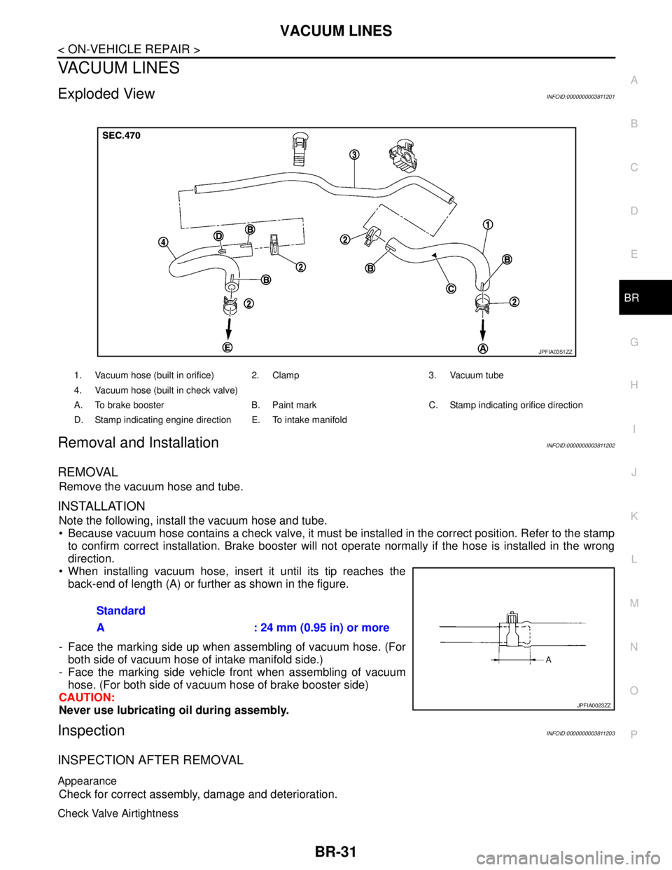
Exploded ViewINFOID:0000000003811201
Removal and InstallationINFOID:0000000003811202
REMOVAL
Remove the vacuum hose and tube.
INSTALLATION
Note the following, install the vacuum hose and tube.
Because vacuum hose contains a check valve, it must be installed in the correct position. Refer to the stamp
to confirm correct installation. Brake booster will not operate normally if the hose is installed in the wrong
direction.
When installing vacuum hose, insert it until its tip reaches the
back-end of length (A) or further as shown in the figure.
- Face the marking side up when assembling of vacuum hose. (For
both side of vacuum hose of intake manifold side.)
- Face the marking side vehicle front when assembling of vacuum
hose. (For both side of vacuum hose of brake booster side)
CAUTION:
Never use lubricating oil during assembly.
InspectionINFOID:0000000003811203
INSPECTION AFTER REMOVAL
Appearance
Check for correct assembly, damage and deterioration.
Check Valve Airtightness
1. Vacuum hose (built in orifice) 2. Clamp 3. Vacuum tube
4. Vacuum hose (built in check valve)
A. To brake booster B. Paint mark C. Stamp indicating orifice direction
D. Stamp indicating engine direction E. To intake manifold
JPFIA0351ZZ
Standard
A : 24 mm (0.95 in) or more
JPFIA0023ZZ
Page 997 of 5121
![NISSAN TEANA 2008 Service Manual BRC-56
< PRECAUTION >[ABS]
PRECAUTIONS
Precaution for Brake Control
INFOID:0000000003766861
When starting engine or when starting vehicle just after starting engine, brake pedal may vibrate or motor NISSAN TEANA 2008 Service Manual BRC-56
< PRECAUTION >[ABS]
PRECAUTIONS
Precaution for Brake Control
INFOID:0000000003766861
When starting engine or when starting vehicle just after starting engine, brake pedal may vibrate or motor](/img/5/57391/w960_57391-996.png)
BRC-56
< PRECAUTION >[ABS]
PRECAUTIONS
Precaution for Brake Control
INFOID:0000000003766861
When starting engine or when starting vehicle just after starting engine, brake pedal may vibrate or motor
operating noise may be heard from engine compartment. This is normal condition.
When an error is indicated by ABS or another warning lamp, collect all necessary information from customer
(what symptoms are present under what conditions) and check for estimate causes before starting diagnos-
tic servicing. Besides electrical system inspection, check brake booster operation, brake fluid level, and oil
leaks.
If tire size and type are used in an improper combination, or brake pads are not Genuine NISSAN parts,
stopping distance or steering stability may deteriorate.
ABS might be out of order or malfunctions by putting a radio (wiring inclusive), an antenna and a lead-in wire
near the control unit.
If aftermarket parts (car stereo, CD player, etc.) have been installed, check for incidents such as harness
pinches, open circuits, and improper wiring.
Precautions for Harness RepairINFOID:0000000003859437
COMMUNICATION LINE
Solder the repaired area and wrap tape around the soldered area.
NOTE:
A fray of twisted lines must be within 110 mm (4.33 in).
Bypass connection is never allowed at the repaired area.
NOTE:
Bypass connection may cause communication error as spliced
wires that are separate from the main line or twisted lines lose
noise immunity.
Replace the applicable harness as an assembly if error is detected
on the shield lines of communication line.
SKIB8766E
SKIB8767E
Page 1091 of 5121
![NISSAN TEANA 2008 Service Manual BRC-150
< PRECAUTION >[VDC/TCS/ABS]
PRECAUTIONS
Precaution for Brake Control
INFOID:0000000003767032
When starting engine or when starting vehicle just after starting engine, brake pedal may vibrate NISSAN TEANA 2008 Service Manual BRC-150
< PRECAUTION >[VDC/TCS/ABS]
PRECAUTIONS
Precaution for Brake Control
INFOID:0000000003767032
When starting engine or when starting vehicle just after starting engine, brake pedal may vibrate](/img/5/57391/w960_57391-1090.png)
BRC-150
< PRECAUTION >[VDC/TCS/ABS]
PRECAUTIONS
Precaution for Brake Control
INFOID:0000000003767032
When starting engine or when starting vehicle just after starting engine, brake pedal may vibrate or motor
operating noise may be heard from engine compartment. This is normal condition.
When an error is indicated by ABS or another warning lamp, collect all necessary information from customer
(what symptoms are present under what conditions) and check for estimate causes before starting diagnos-
tic servicing. Besides electrical system inspection, check brake booster operation, brake fluid level, and oil
leaks.
If tire size and type are used in an improper combination, or brake pads are not Genuine NISSAN parts,
stopping distance or steering stability may deteriorate.
ABS might be out of order or malfunctions by putting a radio (wiring inclusive), an antenna and a lead-in wire
near the control unit.
If aftermarket parts (car stereo, CD player, etc.) have been installed, check for incidents such as harness
pinches, open circuits, and improper wiring.
VDC system may not operate normally or a VDC OFF indicator lamp or SLIP indicator lamp may light.
- When replacing the following parts with parts other than genuine parts or making modifications: Suspension
related parts (shock absorber, spring, bushing, etc.), tires, wheels (other than specified sizes), brake-related
parts (pad, rotor, caliper, etc.), engine-related parts (muffler, ECM, etc.) and body reinforcement-related parts
(roll bar, tower bar, etc.).
- When driving with worn or deteriorated suspension, tires and brake-related parts.
Precautions for Harness RepairINFOID:0000000003843440
COMMUNICATION LINE
Solder the repaired area and wrap tape around the soldered area.
NOTE:
A fray of twisted lines must be within 110 mm (4.33 in).
Bypass connection is never allowed at the repaired area.
NOTE:
Bypass connection may cause communication error as spliced
wires that are separate from the main line or twisted lines lose
noise immunity.
Replace the applicable harness as an assembly if error is detected
on the shield lines of communication line.
SKIB8766E
SKIB8767E
Page 1120 of 5121
CHG-22
< ON-VEHICLE REPAIR >
ALTERNATOR
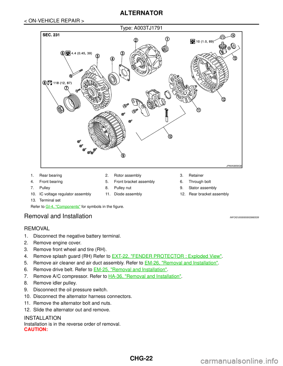
Type: A003TJ1791
Removal and InstallationINFOID:0000000003860539
REMOVAL
1. Disconnect the negative battery terminal.
2. Remove engine cover.
3. Remove front wheel and tire (RH).
4. Remove splash guard (RH) Refer to EXT-22, "
FENDER PROTECTOR : Exploded View".
5. Remove air cleaner and air duct assembly. Refer to EM-26, "
Removal and Installation".
6. Remove drive belt. Refer to EM-25, "
Removal and Installation".
7. Remove A/C compressor. Refer to HA-36, "
Removal and Installation".
8. Remove idler pulley.
9. Disconnect the oil pressure switch.
10. Disconnect the alternator harness connectors.
11. Remove the alternator bolt and nuts.
12. Slide the alternator out and remove.
INSTALLATION
Installation is in the reverse order of removal.
CAUTION:
JPMIA0859GB
1. Rear bearing 2. Rotor assembly 3. Retainer
4. Front bearing 5. Front bracket assembly 6. Through bolt
7. Pulley 8. Pulley nut 9. Stator assembly
10. IC voltage regulator assembly 11. Diode assembly 12. Rear bracket assembly
13. Terminal set
Refer to GI-4, "
Components" for symbols in the figure.
Page 1129 of 5121
CO-6
< PRECAUTION >
PRECAUTIONS
3. Attach liquid gasket tube to the tube presser (commercial ser-
vice tool).
Use Genuine Liquid Gasket or equivalent.
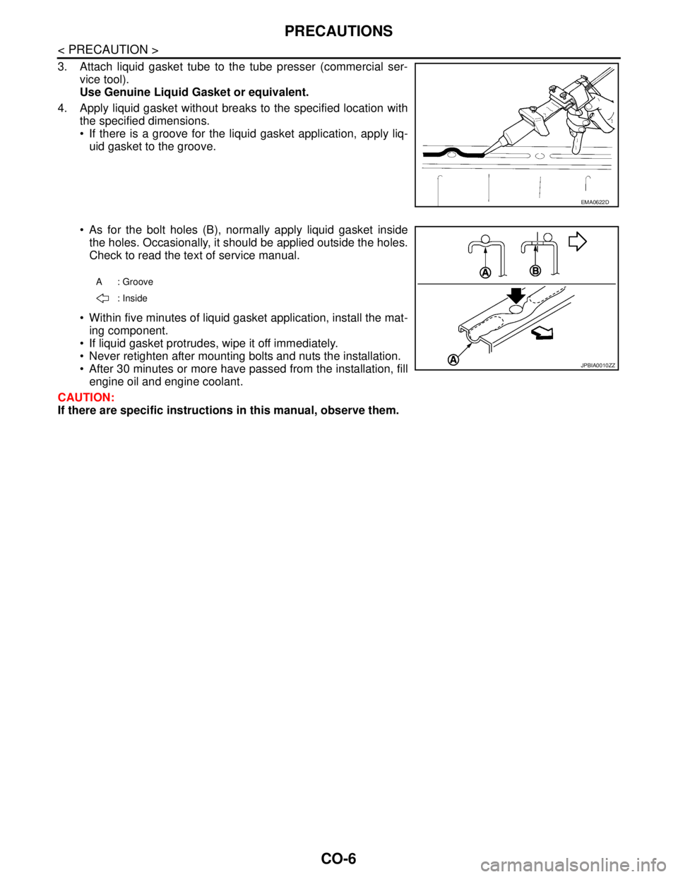
4. Apply liquid gasket without breaks to the specified location with
the specified dimensions.
If there is a groove for the liquid gasket application, apply liq-
uid gasket to the groove.
As for the bolt holes (B), normally apply liquid gasket inside
the holes. Occasionally, it should be applied outside the holes.
Check to read the text of service manual.
Within five minutes of liquid gasket application, install the mat-
ing component.
If liquid gasket protrudes, wipe it off immediately.
Never retighten after mounting bolts and nuts the installation.
After 30 minutes or more have passed from the installation, fill
engine oil and engine coolant.
CAUTION:
If there are specific instructions in this manual, observe them.
EMA0622D
A: Groove
: Inside
JPBIA0010ZZ
Page 1135 of 5121
CO-12
< ON-VEHICLE MAINTENANCE >
RADIATOR
RADIATOR
RADIATOR CAP
RADIATOR CAP : InspectionINFOID:0000000003793170
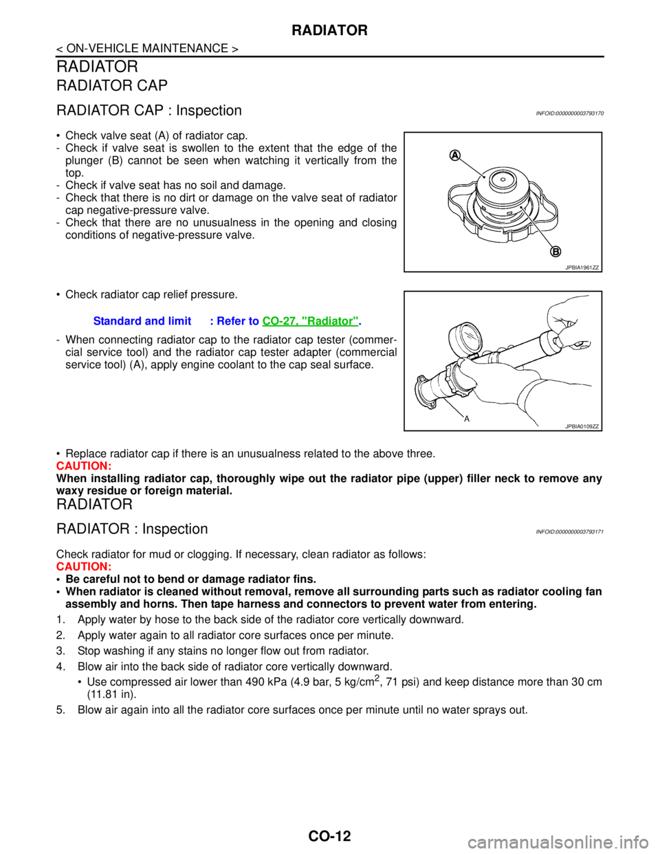
Check valve seat (A) of radiator cap.
- Check if valve seat is swollen to the extent that the edge of the
plunger (B) cannot be seen when watching it vertically from the
top.
- Check if valve seat has no soil and damage.
- Check that there is no dirt or damage on the valve seat of radiator
cap negative-pressure valve.
- Check that there are no unusualness in the opening and closing
conditions of negative-pressure valve.
Check radiator cap relief pressure.
- When connecting radiator cap to the radiator cap tester (commer-
cial service tool) and the radiator cap tester adapter (commercial
service tool) (A), apply engine coolant to the cap seal surface.
Replace radiator cap if there is an unusualness related to the above three.
CAUTION:
When installing radiator cap, thoroughly wipe out the radiator pipe (upper) filler neck to remove any
waxy residue or foreign material.
RADIATOR
RADIATOR : InspectionINFOID:0000000003793171
Check radiator for mud or clogging. If necessary, clean radiator as follows:
CAUTION:
Be careful not to bend or damage radiator fins.
When radiator is cleaned without removal, remove all surrounding parts such as radiator cooling fan
assembly and horns. Then tape harness and connectors to prevent water from entering.
1. Apply water by hose to the back side of the radiator core vertically downward.
2. Apply water again to all radiator core surfaces once per minute.
3. Stop washing if any stains no longer flow out from radiator.
4. Blow air into the back side of radiator core vertically downward.
Use compressed air lower than 490 kPa (4.9 bar, 5 kg/cm
2, 71 psi) and keep distance more than 30 cm
(11.81 in).
5. Blow air again into all the radiator core surfaces once per minute until no water sprays out.
JPBIA1961ZZ
Standard and limit : Refer to CO-27, "Radiator".
JPBIA0109ZZ
Page 1139 of 5121
CO-16
< ON-VEHICLE REPAIR >
COOLING FAN
COOLING FAN
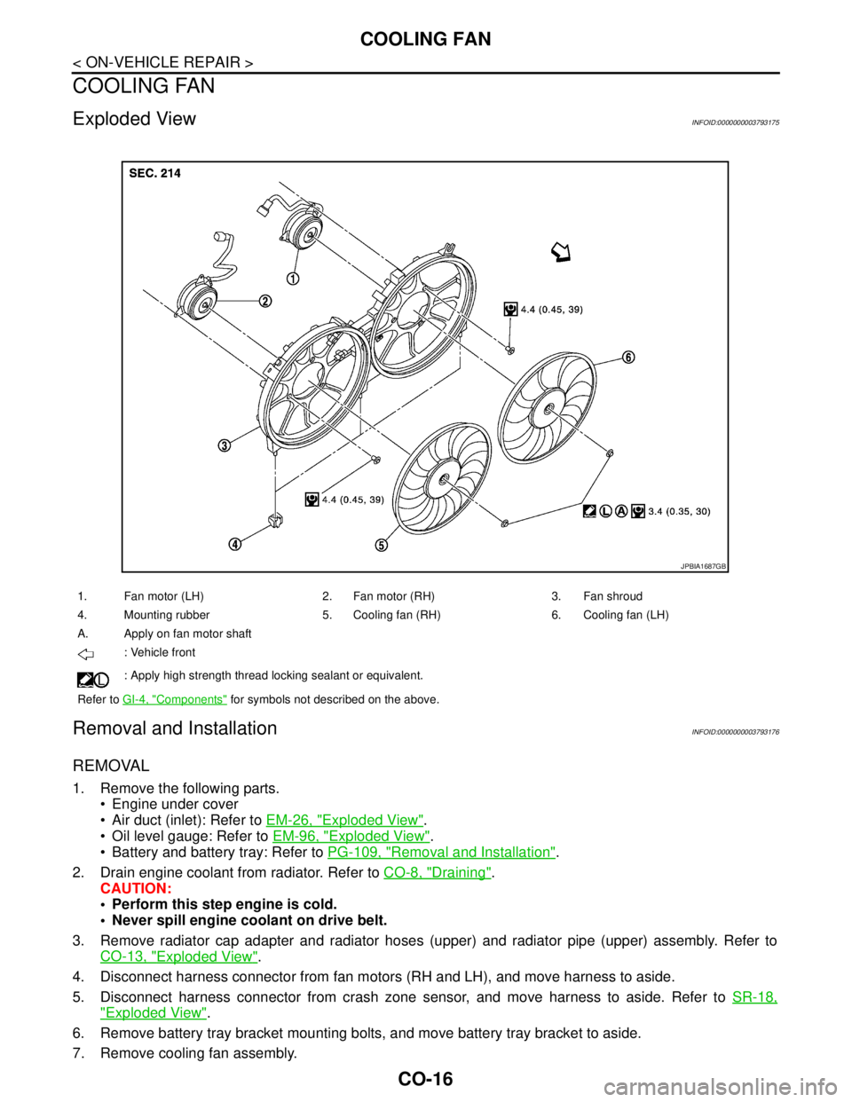
Exploded ViewINFOID:0000000003793175
Removal and InstallationINFOID:0000000003793176
REMOVAL
1. Remove the following parts.
Engine under cover
Air duct (inlet): Refer to EM-26, "
Exploded View".
Oil level gauge: Refer to EM-96, "
Exploded View".
Battery and battery tray: Refer to PG-109, "
Removal and Installation".
2. Drain engine coolant from radiator. Refer to CO-8, "
Draining".
CAUTION:
Perform this step engine is cold.
Never spill engine coolant on drive belt.
3. Remove radiator cap adapter and radiator hoses (upper) and radiator pipe (upper) assembly. Refer to
CO-13, "
Exploded View".
4. Disconnect harness connector from fan motors (RH and LH), and move harness to aside.
5. Disconnect harness connector from crash zone sensor, and move harness to aside. Refer to SR-18,
"Exploded View".
6. Remove battery tray bracket mounting bolts, and move battery tray bracket to aside.
7. Remove cooling fan assembly.
1. Fan motor (LH) 2. Fan motor (RH) 3. Fan shroud
4. Mounting rubber 5. Cooling fan (RH) 6. Cooling fan (LH)
A. Apply on fan motor shaft
: Vehicle front
: Apply high strength thread locking sealant or equivalent.
Refer to GI-4, "
Components" for symbols not described on the above.
JPBIA1687GB
Page 1141 of 5121
CO-18
< ON-VEHICLE REPAIR >
WATER PUMP
WATER PUMP
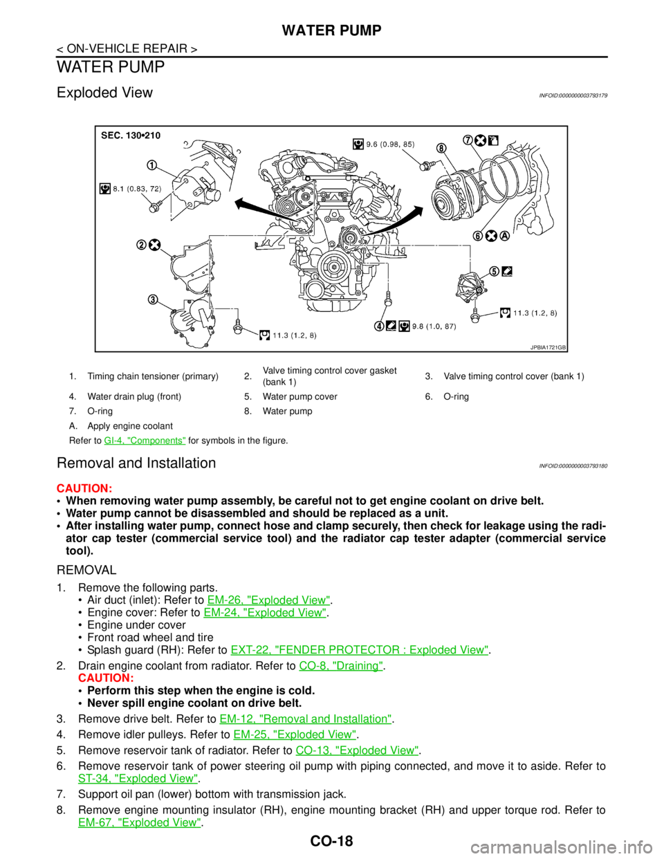
Exploded ViewINFOID:0000000003793179
Removal and InstallationINFOID:0000000003793180
CAUTION:
When removing water pump assembly, be careful not to get engine coolant on drive belt.
Water pump cannot be disassembled and should be replaced as a unit.
After installing water pump, connect hose and clamp securely, then check for leakage using the radi-
ator cap tester (commercial service tool) and the radiator cap tester adapter (commercial service
tool).
REMOVAL
1. Remove the following parts.
Air duct (inlet): Refer to EM-26, "
Exploded View".
Engine cover: Refer to EM-24, "
Exploded View".
Engine under cover
Front road wheel and tire
Splash guard (RH): Refer to EXT-22, "
FENDER PROTECTOR : Exploded View".
2. Drain engine coolant from radiator. Refer to CO-8, "
Draining".
CAUTION:
Perform this step when the engine is cold.
Never spill engine coolant on drive belt.
3. Remove drive belt. Refer to EM-12, "
Removal and Installation".
4. Remove idler pulleys. Refer to EM-25, "
Exploded View".
5. Remove reservoir tank of radiator. Refer to CO-13, "
Exploded View".
6. Remove reservoir tank of power steering oil pump with piping connected, and move it to aside. Refer to
ST-34, "
Exploded View".
7. Support oil pan (lower) bottom with transmission jack.
8. Remove engine mounting insulator (RH), engine mounting bracket (RH) and upper torque rod. Refer to
EM-67, "
Exploded View".
1. Timing chain tensioner (primary) 2.Valve timing control cover gasket
(bank 1)3. Valve timing control cover (bank 1)
4. Water drain plug (front) 5. Water pump cover 6. O-ring
7. O-ring 8. Water pump
A. Apply engine coolant
Refer to GI-4, "
Components" for symbols in the figure.
JPBIA1721GB
Page 1143 of 5121
![NISSAN TEANA 2008 Service Manual CO-20
< ON-VEHICLE REPAIR >
WATER PUMP
b. Screw M8 bolts [pitch: 1.25 mm (0.0492 in) length: approxi-
mately 50 mm (1.97 in)] into water pumps upper and lower
mounting bolt holes until they reach timi NISSAN TEANA 2008 Service Manual CO-20
< ON-VEHICLE REPAIR >
WATER PUMP
b. Screw M8 bolts [pitch: 1.25 mm (0.0492 in) length: approxi-
mately 50 mm (1.97 in)] into water pumps upper and lower
mounting bolt holes until they reach timi](/img/5/57391/w960_57391-1142.png)
CO-20
< ON-VEHICLE REPAIR >
WATER PUMP
b. Screw M8 bolts [pitch: 1.25 mm (0.0492 in) length: approxi-
mately 50 mm (1.97 in)] into water pumps upper and lower
mounting bolt holes until they reach timing chain case. Then,
alternately tighten each bolt for a half turn, and pull out water
pump.
CAUTION:
Pull straight out while preventing vane from contacting
socket in installation area.
Remove water pump without causing sprocket to contact
timing chain.
c. Remove M8 bolts and O-rings from water pump.
CAUTION:
Never disassemble water pump.
INSTALLATION
1. Install new O-rings to water pump.
Apply engine oil and engine coolant to O-rings as shown in the
figure.
Locate O-ring with white paint mark to engine front side.
2. Install water pump.
CAUTION:
Never allow cylinder block to nip O-rings when installing
water pump.
Check that timing chain and water pump sprocket are
engaged.
Insert water pump by tightening mounting bolts alternately and
evenly.
3. Install timing chain tensioner (primary) as follows:
a. Turn crankshaft pulley clockwise so that timing chain on the tim-
ing chain tensioner (primary) side is loose.
JLC357B
PBIC1397E
SLC031B
PBIC4820E