headlamp NISSAN TEANA 2008 Service Manual
[x] Cancel search | Manufacturer: NISSAN, Model Year: 2008, Model line: TEANA, Model: NISSAN TEANA 2008Pages: 5121, PDF Size: 69.03 MB
Page 818 of 5121
BCS
BCS-1
ELECTRICAL & POWER CONTROL
C
D
E
F
G
H
I
J
K
L B
SECTION BCS
A
O
P N
CONTENTS
BODY CONTROL SYSTEM
BASIC INSPECTION ....................................3
INSPECTION AND ADJUSTMENT .....................3
ADDITIONAL SERVICE WHEN REPLACING
CONTROL UNIT (BCM) ...............................................
3
ADDITIONAL SERVICE WHEN REPLACING
CONTROL UNIT (BCM) : Description .......................
3
ADDITIONAL SERVICE WHEN REPLACING
CONTROL UNIT (BCM) : Special Repair Require-
ment ..........................................................................
3
CONFIGURATION (BCM) ...........................................3
CONFIGURATION (BCM) : Description ....................3
CONFIGURATION (BCM) : Special Repair Re-
quirement ..................................................................
4
CONFIGURATION (BCM) : Configuration list ...........5
FUNCTION DIAGNOSIS ...............................6
BODY CONTROL SYSTEM ................................6
System Description ...................................................6
Component Parts Location ........................................7
COMBINATION SWITCH READING SYSTEM
.....
8
System Diagram ........................................................8
System Description ...................................................8
Component Parts Location ......................................11
SIGNAL BUFFER SYSTEM ...............................12
System Diagram ......................................................12
System Description .................................................12
POWER CONSUMPTION CONTROL SYS-
TEM ....................................................................
13
System Diagram ......................................................13
System Description .................................................13
Component Parts Location ......................................15
DIAGNOSIS SYSTEM (BCM) ............................16
COMMON ITEM .........................................................16
COMMON ITEM : CONSULT-III Function (BCM -
COMMON ITEM) .....................................................
16
DOOR LOCK ..............................................................17
DOOR LOCK : CONSULT-III Function (BCM -
DOOR LOCK) ..........................................................
17
REAR WINDOW DEFOGGER ...................................18
REAR WINDOW DEFOGGER : CONSULT-III
Function (BCM - REAR DEFOGGER) .....................
18
BUZZER .....................................................................18
BUZZER : CONSULT-III Function (BCM - BUZZ-
ER) ..........................................................................
19
INT LAMP ...................................................................19
INT LAMP : CONSULT-III Function (BCM - INT
LAMP) ......................................................................
19
HEADLAMP ...............................................................21
HEADLAMP : CONSULT-III Function (BCM -
HEAD LAMP) ...........................................................
21
WIPER ........................................................................23
WIPER : CONSULT-III Function (BCM - WIPER) ....23
FLASHER ...................................................................24
FLASHER : CONSULT-III Function (BCM -
FLASHER) ...............................................................
24
INTELLIGENT KEY ....................................................25
INTELLIGENT KEY : CONSULT-III Function
(BCM - INTELLIGENT KEY) ....................................
25
COMB SW ..................................................................28
COMB SW : CONSULT-III Function (BCM -
COMB SW) ..............................................................
28
BCM ...........................................................................28
BCM : CONSULT-III Function (BCM - BCM) ...........28
IMMU ..........................................................................29
IMMU : CONSULT-III Function (BCM - IMMU) ........29
Page 823 of 5121
BCS-6
< FUNCTION DIAGNOSIS >
BODY CONTROL SYSTEM
FUNCTION DIAGNOSIS
BODY CONTROL SYSTEM
System DescriptionINFOID:0000000003809584
OUTLINE
BCM (Body Control Module) controls the various electrical components. It inputs the information required to
the control from CAN communication and the signal received from each switch and sensor.
BCM has combination switch reading function for reading the operation status of combination switches (light,
turn signal, wiper and washer) in addition to a function for controlling the operation of various electrical com-
ponents. It also has the signal transmission function as the passed point of signal and the power saving con-
trol function that reduces the power consumption with the ignition switch OFF.
BCM is equipped with the diagnosis function that performs the diagnosis with CONSULT-III and various set-
tings.
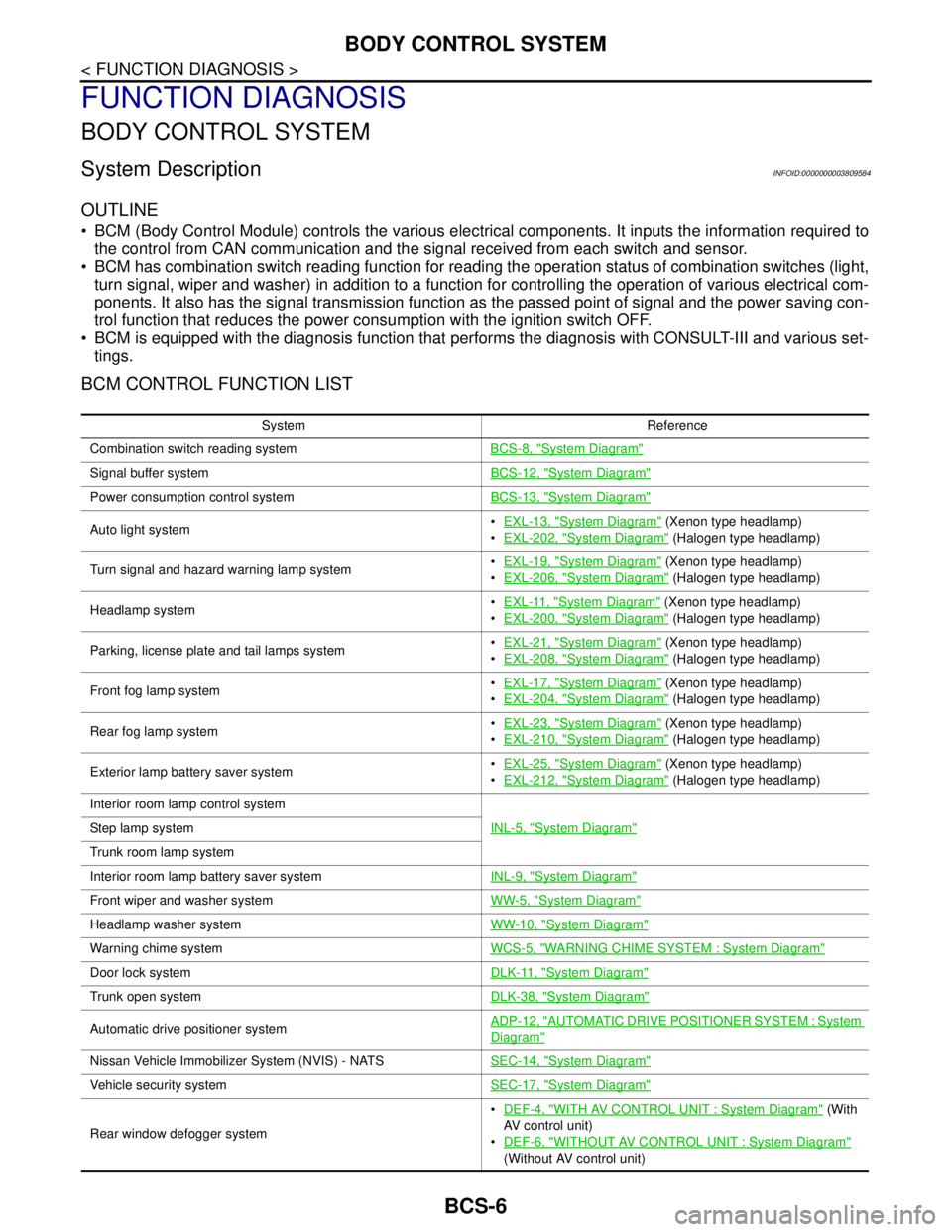
BCM CONTROL FUNCTION LIST
System Reference
Combination switch reading systemBCS-8, "
System Diagram"
Signal buffer systemBCS-12, "System Diagram"
Power consumption control systemBCS-13, "System Diagram"
Auto light systemEXL-13, "System Diagram" (Xenon type headlamp)
EXL-202, "
System Diagram" (Halogen type headlamp)
Turn signal and hazard warning lamp systemEXL-19, "
System Diagram" (Xenon type headlamp)
EXL-206, "
System Diagram" (Halogen type headlamp)
Headlamp systemEXL-11, "
System Diagram" (Xenon type headlamp)
EXL-200, "
System Diagram" (Halogen type headlamp)
Parking, license plate and tail lamps systemEXL-21, "
System Diagram" (Xenon type headlamp)
EXL-208, "
System Diagram" (Halogen type headlamp)
Front fog lamp systemEXL-17, "
System Diagram" (Xenon type headlamp)
EXL-204, "
System Diagram" (Halogen type headlamp)
Rear fog lamp systemEXL-23, "
System Diagram" (Xenon type headlamp)
EXL-210, "
System Diagram" (Halogen type headlamp)
Exterior lamp battery saver systemEXL-25, "
System Diagram" (Xenon type headlamp)
EXL-212, "
System Diagram" (Halogen type headlamp)
Interior room lamp control system
INL-5, "
System Diagram"Step lamp system
Trunk room lamp system
Interior room lamp battery saver systemINL-9, "
System Diagram"
Front wiper and washer systemWW-5, "System Diagram"
Headlamp washer systemWW-10, "System Diagram"
Warning chime systemWCS-5, "WARNING CHIME SYSTEM : System Diagram"
Door lock systemDLK-11, "System Diagram"
Trunk open systemDLK-38, "System Diagram"
Automatic drive positioner systemADP-12, "AUTOMATIC DRIVE POSITIONER SYSTEM : System
Diagram"
Nissan Vehicle Immobilizer System (NVIS) - NATSSEC-14, "System Diagram"
Vehicle security systemSEC-17, "System Diagram"
Rear window defogger systemDEF-4, "
WITH AV CONTROL UNIT : System Diagram" (With
AV control unit)
DEF-6, "
WITHOUT AV CONTROL UNIT : System Diagram"
(Without AV control unit)
Page 825 of 5121
BCS-8
< FUNCTION DIAGNOSIS >
COMBINATION SWITCH READING SYSTEM
COMBINATION SWITCH READING SYSTEM
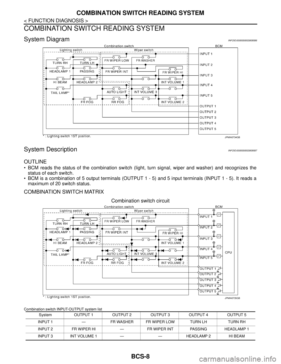
System DiagramINFOID:0000000003809586
System DescriptionINFOID:0000000003809587
OUTLINE
BCM reads the status of the combination switch (light, turn signal, wiper and washer) and recognizes the
status of each switch.
BCM is a combination of 5 output terminals (OUTPUT 1 - 5) and 5 input terminals (INPUT 1 - 5). It reads a
maximum of 20 switch status.
COMBINATION SWITCH MATRIX
Combination switch circuit
Combination switch INPUT-OUTPUT system list
JPMIA0734GB
System OUTPUT 1 OUTPUT 2 OUTPUT 3 OUTPUT 4 OUTPUT 5
INPUT 1 — FR WASHER FR WIPER LOW TURN LH TURN RH
INPUT 2 FR WIPER HI — FR WIPER INT PASSING HEADLAMP 1
INPUT 3 INT VOLUME 1 — — HEADLAMP 2 HI BEAM
JPMIA0735GB
Page 826 of 5121
BCS
COMBINATION SWITCH READING SYSTEM
BCS-9
< FUNCTION DIAGNOSIS >
C
D
E
F
G
H
I
J
K
L B A
O
P N
NOTE:
Headlamp has a dual system switch.
COMBINATION SWITCH READING FUNCTION
Description
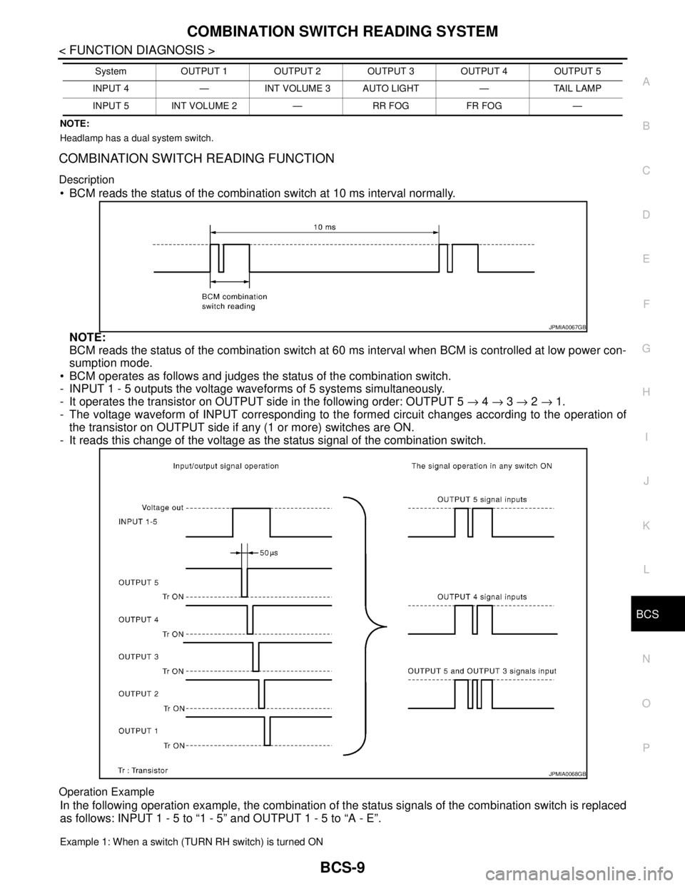
BCM reads the status of the combination switch at 10 ms interval normally.
NOTE:
BCM reads the status of the combination switch at 60 ms interval when BCM is controlled at low power con-
sumption mode.
BCM operates as follows and judges the status of the combination switch.
- INPUT 1 - 5 outputs the voltage waveforms of 5 systems simultaneously.
- It operates the transistor on OUTPUT side in the following order: OUTPUT 5 → 4 → 3 → 2 → 1.
- The voltage waveform of INPUT corresponding to the formed circuit changes according to the operation of
the transistor on OUTPUT side if any (1 or more) switches are ON.
- It reads this change of the voltage as the status signal of the combination switch.
Operation Example
In the following operation example, the combination of the status signals of the combination switch is replaced
as follows: INPUT 1 - 5 to “1 - 5” and OUTPUT 1 - 5 to “A - E”.
Example 1: When a switch (TURN RH switch) is turned ON
INPUT 4 — INT VOLUME 3 AUTO LIGHT — TAIL LAMP
INPUT 5 INT VOLUME 2 — RR FOG FR FOG —System OUTPUT 1 OUTPUT 2 OUTPUT 3 OUTPUT 4 OUTPUT 5
JPMIA0067GB
JPMIA0068GB
Page 838 of 5121
BCS
DIAGNOSIS SYSTEM (BCM)
BCS-21
< FUNCTION DIAGNOSIS >
C
D
E
F
G
H
I
J
K
L B A
O
P N
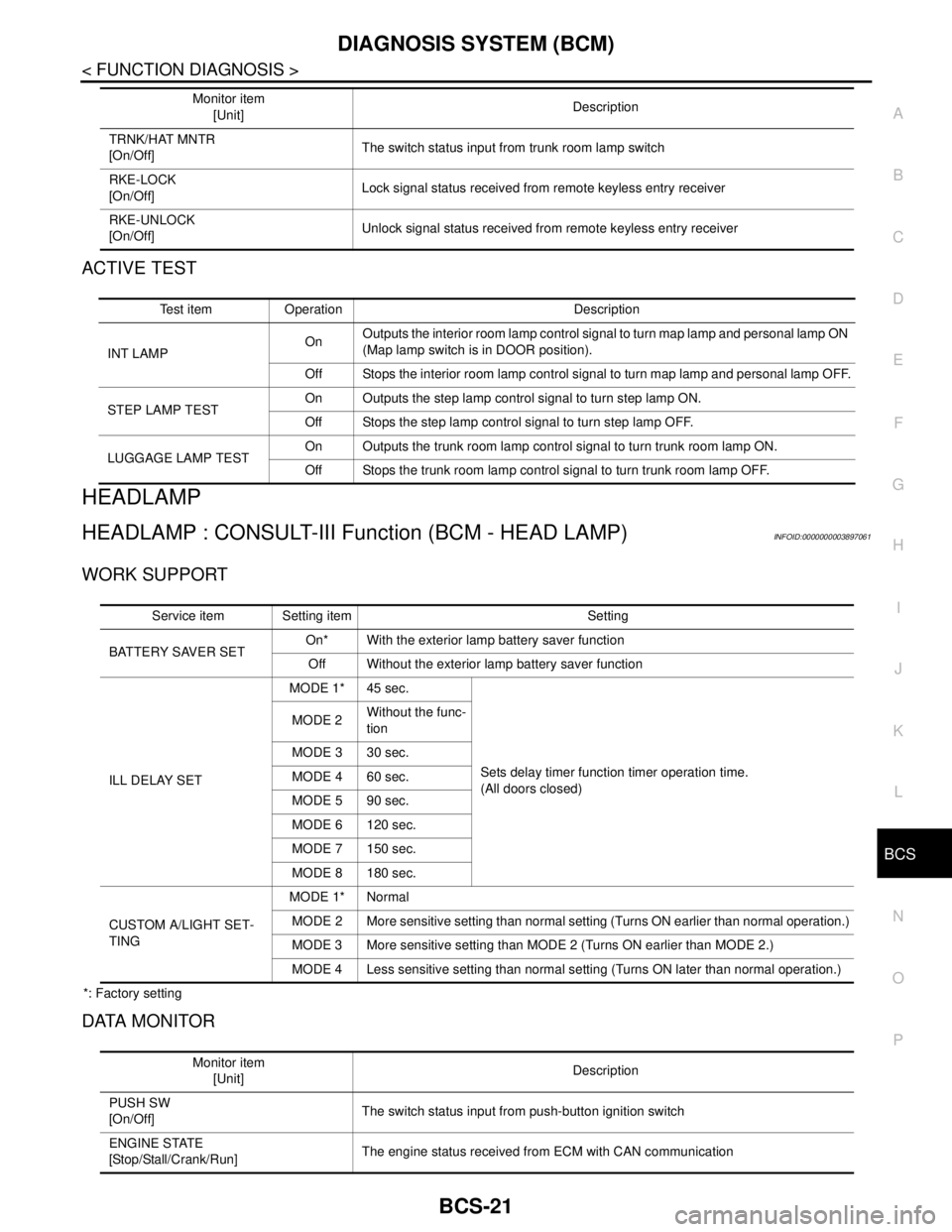
ACTIVE TEST
HEADLAMP
HEADLAMP : CONSULT-III Function (BCM - HEAD LAMP)INFOID:0000000003897061
WORK SUPPORT
*: Factory setting
DATA MONITOR
TRNK/HAT MNTR
[On/Off]The switch status input from trunk room lamp switch
RKE-LOCK
[On/Off]Lock signal status received from remote keyless entry receiver
RKE-UNLOCK
[On/Off]Unlock signal status received from remote keyless entry receiver Monitor item
[Unit]Description
Test item Operation Description
INT LAMPOnOutputs the interior room lamp control signal to turn map lamp and personal lamp ON
(Map lamp switch is in DOOR position).
Off Stops the interior room lamp control signal to turn map lamp and personal lamp OFF.
STEP LAMP TESTOn Outputs the step lamp control signal to turn step lamp ON.
Off Stops the step lamp control signal to turn step lamp OFF.
LUGGAGE LAMP TESTOn Outputs the trunk room lamp control signal to turn trunk room lamp ON.
Off Stops the trunk room lamp control signal to turn trunk room lamp OFF.
Service item Setting item Setting
BATTERY SAVER SETOn* With the exterior lamp battery saver function
Off Without the exterior lamp battery saver function
ILL DELAY SETMODE 1* 45 sec.
Sets delay timer function timer operation time.
(All doors closed) MODE 2Without the func-
tion
MODE 3 30 sec.
MODE 4 60 sec.
MODE 5 90 sec.
MODE 6 120 sec.
MODE 7 150 sec.
MODE 8 180 sec.
CUSTOM A/LIGHT SET-
TINGMODE 1* Normal
MODE 2 More sensitive setting than normal setting (Turns ON earlier than normal operation.)
MODE 3 More sensitive setting than MODE 2 (Turns ON earlier than MODE 2.)
MODE 4 Less sensitive setting than normal setting (Turns ON later than normal operation.)
Monitor item
[Unit]Description
PUSH SW
[On/Off]The switch status input from push-button ignition switch
ENGINE STATE
[Stop/Stall/Crank/Run]The engine status received from ECM with CAN communication
Page 839 of 5121
![NISSAN TEANA 2008 Service Manual BCS-22
< FUNCTION DIAGNOSIS >
DIAGNOSIS SYSTEM (BCM)
ACTIVE TEST
VEH SPEED 1
[km/h]The value of the vehicle speed received from combination meter with CAN commu-
nication
KEY SW-SLOT
[On/Off]Key switc NISSAN TEANA 2008 Service Manual BCS-22
< FUNCTION DIAGNOSIS >
DIAGNOSIS SYSTEM (BCM)
ACTIVE TEST
VEH SPEED 1
[km/h]The value of the vehicle speed received from combination meter with CAN commu-
nication
KEY SW-SLOT
[On/Off]Key switc](/img/5/57391/w960_57391-838.png)
BCS-22
< FUNCTION DIAGNOSIS >
DIAGNOSIS SYSTEM (BCM)
ACTIVE TEST
VEH SPEED 1
[km/h]The value of the vehicle speed received from combination meter with CAN commu-
nication
KEY SW-SLOT
[On/Off]Key switch status input from key slot
TURN SIGNAL R
[On/Off]
Each switch status that BCM detects from the combination switch reading function TURN SIGNAL L
[On/Off]
TA I L L A M P S W
[On/Off]
HI BEAM SW
[On/Off]
HEAD LAMP SW1
[On/Off]
HEAD LAMP SW2
[On/Off]
PASSING SW
[On/Off]
AUTO LIGHT SW
[On/Off]
FR FOG SW
[On/Off]
RR FOG SW
[On/Off]
DOOR SW-DR
[On/Off]The switch status input from front door switch (driver side)
DOOR SW-AS
[On/Off]The switch status input from front door switch (passenger side)
DOOR SW-RR
[On/Off]The switch status input from rear door switch RH
DOOR SW- RL
[On/Off]The switch status input from rear door switch LH
DOOR SW-BK
[On/Off]NOTE:
The item is indicated, but not monitored.
OPTICAL SENSOR
[V]The value of exterior brightness voltage input from the optical sensor Monitor item
[Unit]Description
Test item Operation Description
TA I L L A M POnTransmits the position light request signal to IPDM E/R with CAN com-
munication to turn the tail lamp ON.
Off Stops the position light request signal transmission.
HEAD LAMPHiTransmits the high beam request signal with CAN communication to turn
the headlamp (HI).
LowTransmits the low beam request signal with CAN communication to turn
the headlamp (LO).
Off Stops the high & low beam request signal transmission.
FR FOG LAMPOnTransmits the front fog lights request signal to IPDM E/R with CAN com-
munication to turn the front fog lamp ON.
Off Stops the front fog lights request signal transmission.
Page 840 of 5121
BCS
DIAGNOSIS SYSTEM (BCM)
BCS-23
< FUNCTION DIAGNOSIS >
C
D
E
F
G
H
I
J
K
L B A
O
P N
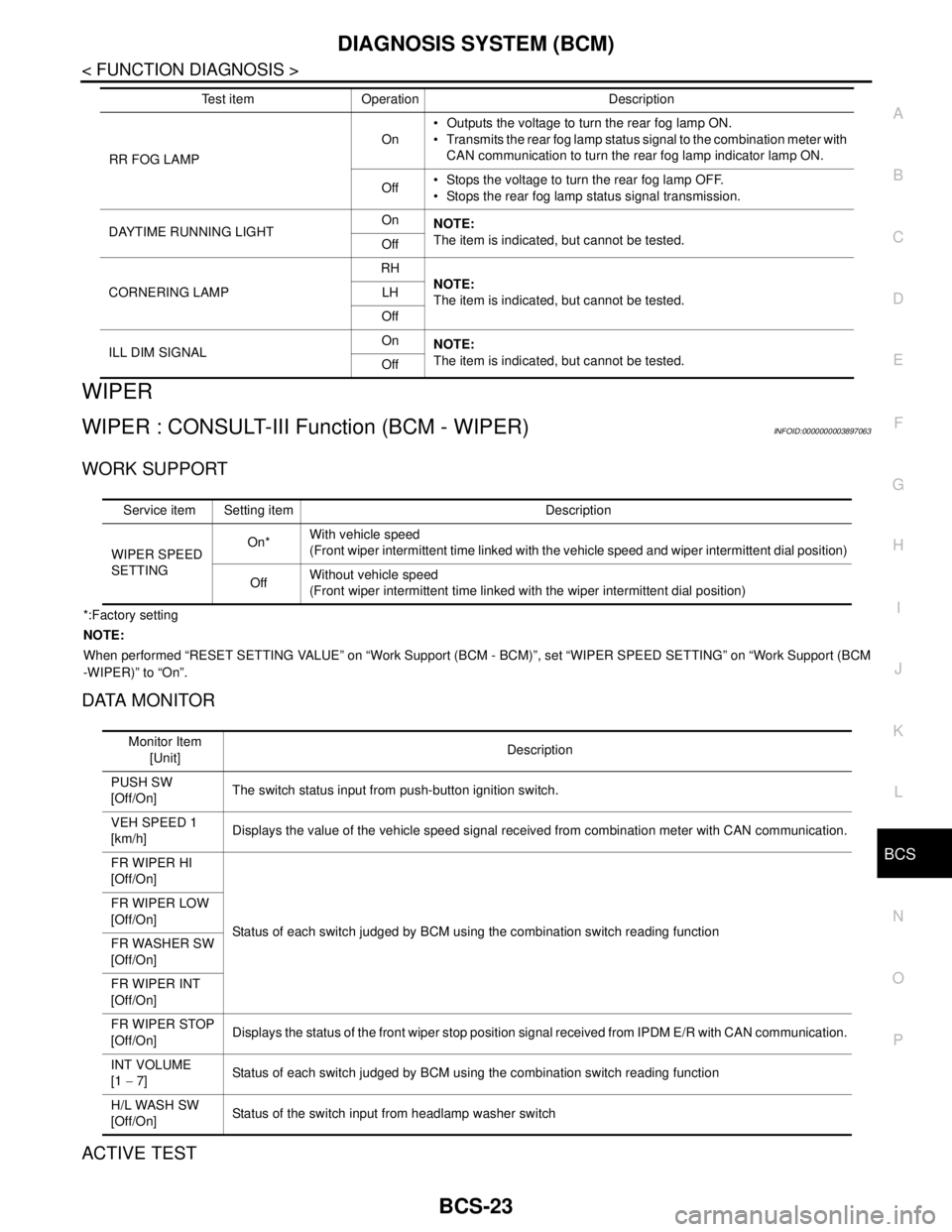
WIPER
WIPER : CONSULT-III Function (BCM - WIPER)INFOID:0000000003897063
WORK SUPPORT
*:Factory setting
NOTE:
When performed “RESET SETTING VALUE” on “Work Support (BCM - BCM)”, set “WIPER SPEED SETTING” on “Work Support (BCM
-WIPER)” to “On”.
DATA MONITOR
ACTIVE TEST
RR FOG LAMPOn Outputs the voltage to turn the rear fog lamp ON.
Transmits the rear fog lamp status signal to the combination meter with
CAN communication to turn the rear fog lamp indicator lamp ON.
Off Stops the voltage to turn the rear fog lamp OFF.
Stops the rear fog lamp status signal transmission.
DAYTIME RUNNING LIGHTOn
NOTE:
The item is indicated, but cannot be tested.
Off
CORNERING LAMPRH
NOTE:
The item is indicated, but cannot be tested. LH
Off
ILL DIM SIGNALOn
NOTE:
The item is indicated, but cannot be tested.
Off Test item Operation Description
Service item Setting item Description
WIPER SPEED
SETTINGOn*With vehicle speed
(Front wiper intermittent time linked with the vehicle speed and wiper intermittent dial position)
OffWithout vehicle speed
(Front wiper intermittent time linked with the wiper intermittent dial position)
Monitor Item
[Unit]Description
PUSH SW
[Off/On]The switch status input from push-button ignition switch.
VEH SPEED 1
[km/h]Displays the value of the vehicle speed signal received from combination meter with CAN communication.
FR WIPER HI
[Off/On]
Status of each switch judged by BCM using the combination switch reading function FR WIPER LOW
[Off/On]
FR WASHER SW
[Off/On]
FR WIPER INT
[Off/On]
FR WIPER STOP
[Off/On]Displays the status of the front wiper stop position signal received from IPDM E/R with CAN communication.
INT VOLUME
[1 − 7] Status of each switch judged by BCM using the combination switch reading function
H/L WASH SW
[Off/On]Status of the switch input from headlamp washer switch
Page 841 of 5121

BCS-24
< FUNCTION DIAGNOSIS >
DIAGNOSIS SYSTEM (BCM)
FLASHER
FLASHER : CONSULT-III Function (BCM - FLASHER)INFOID:0000000003897062
WORK SUPPORT
*: Factory setting
DATA MONITOR
ACTIVE TEST
Test item Operation Description
FRONT WIPERHiTransmits the front wiper request signal (HI) to IPDM E/R with CAN communication to
operate the front wiper HI operation.
LoTransmits the front wiper request signal (LO) to IPDM E/R with CAN communication to
operate the front wiper LO operation.
INTTransmits the front wiper request signal (INT) to IPDM E/R with CAN communication to
operate the front wiper INT operation.
Off Stops transmitting the front wiper request signal to stop the front wiper operation.
HEADLAMP WASHER OnTransmits the headlamp washer request signal to IPDM E/R with CAN communication to
operate the headlamp washer operation.
Service item Setting item Setting
HAZARD ANSWER
BACKLock Only* With locking only
Sets the hazard warning lamp answer back function
when the door is lock/unlock with the request switch or
the key fob. Unlk Only With unlocking only
Lock/Unlk With locking/unlocking
Off Without the function
Monitor item
[Unit]Description
REQ SW-DR
[On/Off]The switch status input from the request switch (driver side)
REQ SW-AS
[On/Off]The switch status input from the request switch (passenger side)
PUSH SW
[On/Off]The switch status input from the push-button ignition switch
TURN SIGNAL R
[On/Off]
Each switch status that BCM detects from the combination switch reading function
TURN SIGNAL L
[On/Off]
HAZARD SW
[On/Off]The switch status input from the hazard switch
RKE-LOCK
[On/Off]Lock signal status received from the remote keyless entry receiver
RKE-UNLOCK
[On/Off]Unlock signal status received from the remote keyless entry receiver
RKE-PANIC
[On/Off]Panic alarm signal status received from the remote keyless entry receiver
Test item Operation Description
FLASHERRH Outputs the voltage to blink the right side turn signal lamps.
LH Outputs the voltage to blink the left side turn signal lamps.
Off Stops the voltage to turn the turn signal lamps OFF.
Page 845 of 5121

BCS-28
< FUNCTION DIAGNOSIS >
DIAGNOSIS SYSTEM (BCM)
COMB SW
COMB SW : CONSULT-III Function (BCM - COMB SW)INFOID:0000000003809604
DATA MONITOR
BCM
BCM : CONSULT-III Function (BCM - BCM)INFOID:0000000003809605
WORK SUPPORT
NOTE:KEY SLOT ILLUMIThis test is able to check key slot illumination operation.
Key slot illumination illuminates when “ON” on CONSULT-III screen is touched.
TRUNK/BACK DOORThis test is able to check trunk lid opener actuator open operation.
This actuator opens when “OPEN” on CONSULT-III screen is touched. Te s t i t e m D e s c r i p t i o n
Monitor item [UNIT] Description
FR WIPER HI
[Off/On]Displays the status of the FR WIPER HI switch in combination switch judged by BCM with the combination
switch reading function.
FR WIPER LOW
[Off/On]Displays the status of the FR WIPER LOW switch in combination switch judged by BCM with the combination
switch reading function.
FR WASHER SW
[Off/On]Displays the status of the FR WASHER switch in combination switch judged by BCM with the combination
switch reading function.
FR WIPER INT
[Off/On]Displays the status of the FR WIPER INT switch in combination switch judged by BCM with the combination
switch reading function.
FR WIPER STOP
[Off/On]Displays the status of the front wiper stop position signal received from IPDM E/R via CAN communication.
INT VOLUME
[1 - 7]Displays the status of wiper intermittent dial position judged by BCM with the combination switch reading
function.
TURN SIGNAL R
[Off/On]Displays the status of the TURN RH switch in combination switch judged by BCM with the combination switch
reading function.
TURN SIGNAL L
[Off/On]Displays the status of the TURN LH switch in combination switch judged by BCM with the combination switch
reading function.
TAIL LAMP SW
[Off/On]Displays the status of the TAIL LAMP switch in combination switch judged by BCM with the combination
switch reading function.
HI BEAM SW
[Off/On]Displays the status of the HI BEAM switch in combination switch judged by BCM with the combination switch
reading function.
HEAD LAMP SW 1
[Off/On]Displays the status of the HEADLAMP 1 switch in combination switch judged by BCM with the combination
switch reading function.
HEAD LAMP SW 2
[Off/On]Displays the status of the HEADLAMP 2 switch in combination switch judged by BCM with the combination
switch reading function.
PASSING SW
[Off/On]Displays the status of the PASSING switch in combination switch judged by BCM with the combination switch
reading function.
AUTO LIGHT SW
[Off/On]Displays the status of the AUTO LIGHT switch in combination switch judged by BCM with the combination
switch reading function.
FR FOG SW
[Off/On]Displays the status of the FR FOG switch in combination switch judged by BCM with the combination switch
reading function.
RR FOG SW
[Off/On]Displays the status of the RR FOG switch in combination switch judged by BCM with the combination switch
reading function.
Item Description
RESET SETTING VALUE Return a value set with Work Support of each system to a default value in factory shipment.
Page 849 of 5121

BCS-32
< FUNCTION DIAGNOSIS >
DIAGNOSIS SYSTEM (BCM)
WORK SUPPORT
ACTIVE TEST
SIGNAL BUFFER
SIGNAL BUFFER : CONSULT-III Function (BCM - SIGNAL BUFFER)INFOID:0000000003809611
DATA MONITOR
ACTIVE TEST
CDL LOCK SW Indicates [ON/OFF] condition of lock signal from door lock/unlock switch.
CDL UNLOCK SW Indicates [ON/OFF] condition of unlock signal from door lock/unlock switch.
KEY CYL LK-SWNOTE:
This is displayed even when it is not equipped.
KEY CYL UN-SWNOTE:
This is displayed even when it is not equipped.
KEY CYL SW-TRNOTE:
This is displayed even when it is not equipped.
TR/BD OPEN SW Indicates [ON/OFF] condition of trunk lid opener switch.
TRNK/HAT MNTR Indicates [ON/OFF] condition of trunk room lamp switch.
RKE-LOCK Indicates [ON/OFF] condition of LOCK signal from Intelligent Key.
RKE-UNLOCK Indicates [ON/OFF] condition of UNLOCK signal from Intelligent Key.
RKE-TR/BD Indicates [ON/OFF] condition of TRUNK LID OPEN signal from Intelligent Key. Monitored Item Description
Test Item Description
SECURITY ALARM SET This mode is able to confirm and change security alarm ON-OFF setting.
THEFT ALM TRGThe switch which triggered vehicle security alarm is recorded. This mode is able to confirm and
erase the record of vehicle security alarm. The trigger data can be erased by touching “CLEAR” on
CONSULT-III screen.
Test Item Description
THEFT INDThis test is able to check security indicator lamp operation. The lamp will be turned on when “ON”
on CONSULT-III screen is touched.
HEADLAMP(HI)This test is able to check vehicle security lamp operation. The headlamps will be activated for 0.5
seconds after “ON” on CONSULT-III screen is touched.
FLASHERThis test is able to check vehicle security hazard lamp operation. The hazard lamps will be activat-
ed after “ON” on CONSULT-III screen is touched.
Monitor item [UNIT] Description
PUSH SW
[Off/On]Displays the status of the push-button ignition switch (push switch) judged by BCM.
Te s t i t e mOpera-
tionDescription
OIL PRESSURE SWOff OFF
OnBCM transmits the oil pressure switch signal to the combination meter via CAN communica-
tion, which illuminates the oil pressure warning lamp in the combination meter.