key NISSAN TEANA 2008 Service Manual
[x] Cancel search | Manufacturer: NISSAN, Model Year: 2008, Model line: TEANA, Model: NISSAN TEANA 2008Pages: 5121, PDF Size: 69.03 MB
Page 7 of 5121

ADP-1
BODY INTERIOR
C
D
E
F
G
H
I
K
L
M
SECTION ADP
A
B
ADP
N
O
P
CONTENTS
AUTOMATIC DRIVE POSITIONER
BASIC INSPECTION ....................................4
DIAGNOSIS AND REPAIR WORKFLOW ..........4
Work Flow .................................................................4
INSPECTION AND ADJUSTMENT .....................7
ADDITIONAL SERVICE WHEN REMOVING BAT-
TERY NEGATIVE TERMINAL .....................................
7
ADDITIONAL SERVICE WHEN REMOVING
BATTERY NEGATIVE TERMINAL : Description ......
7
ADDITIONAL SERVICE WHEN REMOVING
BATTERY NEGATIVE TERMINAL : Special Re-
pair Requirement .......................................................
7
ADDITIONAL SERVICE WHEN REPLACING
CONTROL UNIT ..........................................................
7
ADDITIONAL SERVICE WHEN REPLACING
CONTROL UNIT : Description ..................................
7
ADDITIONAL SERVICE WHEN REPLACING
CONTROL UNIT : Special Repair Requirement .......
7
SYSTEM INITIALIZATION ..........................................8
SYSTEM INITIALIZATION : Description ...................8
SYSTEM INITIALIZATION : Special Repair Re-
quirement ..................................................................
8
MEMORY STORING ....................................................8
MEMORY STORING : Description ............................8
MEMORY STORING : Special Repair Require-
ment ..........................................................................
9
SYSTEM SETTING ......................................................9
SYSTEM SETTING : Description ..............................9
SYSTEM SETTING : Special Repair Requirement
....
10
FUNCTION DIAGNOSIS ..............................12
AUTOMATIC DRIVE POSITIONER SYSTEM ....12
AUTOMATIC DRIVE POSITIONER SYSTEM ...........12
AUTOMATIC DRIVE POSITIONER SYSTEM :
System Diagram ......................................................
12
AUTOMATIC DRIVE POSITIONER SYSTEM :
System Description ..................................................
12
AUTOMATIC DRIVE POSITIONER SYSTEM :
Component Parts Location ......................................
14
AUTOMATIC DRIVE POSITIONER SYSTEM :
Component Description ..........................................
15
MANUAL FUNCTION ................................................16
MANUAL FUNCTION : System Diagram ................16
MANUAL FUNCTION : System Description ............16
MANUAL FUNCTION : Component Parts Loca-
tion ...........................................................................
17
MANUAL FUNCTION : Component Description .....18
MEMORY FUNCTION ................................................18
MEMORY FUNCTION : System Diagram ...............19
MEMORY FUNCTION : System Description ...........19
MEMORY FUNCTION : Component Parts Loca-
tion ...........................................................................
21
MEMORY FUNCTION : Component Description ....22
EXIT ASSIST FUNCTION ..........................................22
EXIT ASSIST FUNCTION : System Diagram ..........23
EXIT ASSIST FUNCTION : System Description .....23
EXIT ASSIST FUNCTION : Component Parts Lo-
cation .......................................................................
25
EXIT ASSIST FUNCTION :
Component Description ..........................................
26
ENTRY ASSIST FUNCTION ......................................26
ENTRY ASSIST FUNCTION : System Diagram .....27
ENTRY ASSIST FUNCTION : System Description
....
27
ENTRY ASSIST FUNCTION : Component Parts
Location ...................................................................
29
ENTRY ASSIST FUNCTION :
Component Description ..........................................
30
INTELLIGENT KEY INTERLOCK FUNCTION ..........30
Page 8 of 5121

ADP-2
INTELLIGENT KEY INTERLOCK FUNCTION :
System Diagram .....................................................
31
INTELLIGENT KEY INTERLOCK FUNCTION :
System Description .................................................
31
INTELLIGENT KEY INTERLOCK FUNCTION :
Component Parts Location .....................................
33
INTELLIGENT KEY INTERLOCK FUNCTION :
Component Description .........................................
34
DIAGNOSIS SYSTEM (DRIVER SEAT CON-
TROL UNIT) .......................................................
35
Diagnosis Description .............................................35
CONSULT-III Function ...........................................35
COMPONENT DIAGNOSIS ........................38
U1000 CAN COMM CIRCUIT ............................38
Description ..............................................................38
DTC Logic ...............................................................38
Diagnosis Procedure .............................................38
Special Repair Requirement ...................................38
U1010 CONTROL UNIT (CAN) .........................39
Description ..............................................................39
DTC Logic ...............................................................39
Diagnosis Procedure ..............................................39
B2130 EEPROM ................................................40
DTC Logic ...............................................................40
Diagnosis Procedure .............................................40
B2112 SLIDING MOTOR ...................................41
Description ..............................................................41
DTC Logic ...............................................................41
Diagnosis Procedure .............................................41
B2113 RECLINING MOTOR ..............................43
Description ..............................................................43
DTC Logic ...............................................................43
Diagnosis Procedure .............................................43
POWER SUPPLY AND GROUND CIRCUIT .....45
DRIVER SEAT CONTROL UNIT ..............................45
DRIVER SEAT CONTROL UNIT :
Diagnosis Procedure .............................................
45
SLIDING SWITCH ..............................................46
Description ..............................................................46
Component Function Check .................................46
Diagnosis Procedure .............................................46
Component Inspection ............................................47
RECLINING SWITCH ........................................48
Description ..............................................................48
Component Function Check .................................48
Diagnosis Procedure .............................................48
Component Inspection ............................................49
LIFTING SWITCH (FRONT) ..............................50
Description ..............................................................50
Component Function Check .................................50
Diagnosis Procedure ..............................................50
Component Inspection ............................................51
LIFTING SWITCH (REAR) ................................52
Description ..............................................................52
Component Function Check ..................................52
Diagnosis Procedure ..............................................52
Component Inspection ............................................53
SEAT MEMORY SWITCH .................................54
Description ..............................................................54
Component Function Check ..................................54
Diagnosis Procedure ..............................................54
Component Inspection ............................................55
POWER SEAT SWITCH GROUND CIRCUIT ...57
Diagnosis Procedure ..............................................57
FRONT DOOR SWITCH (DRIVER SIDE) .........58
Description ..............................................................58
Component Function Check ...................................58
Diagnosis Procedure ...............................................58
Component Inspection ............................................59
SLIDING SENSOR ............................................60
Description ..............................................................60
Component Function Check ..................................60
Diagnosis Procedure ..............................................60
RECLINING SENSOR .......................................62
Description ..............................................................62
Component Function Check ..................................62
Diagnosis Procedure ..............................................62
LIFTING SENSOR (FRONT) .............................64
Description ..............................................................64
Component Function Check ..................................64
Diagnosis Procedure ..............................................64
LIFTING SENSOR (REAR) ...............................66
Description ..............................................................66
Component Function Check ..................................66
Diagnosis Procedure ..............................................66
SLIDING MOTOR ..............................................68
Description ..............................................................68
Component Function Check ..................................68
Diagnosis Procedure ..............................................68
RECLINING MOTOR .........................................70
Description ..............................................................70
Component Function Check ..................................70
Diagnosis Procedure ..............................................70
LIFTING MOTOR (FRONT) ...............................72
Description ..............................................................72
Component Function Check ..................................72
Diagnosis Procedure ..............................................72
LIFTING MOTOR (REAR) .................................74
Description ..............................................................74
Component Function Check ..................................74
Page 9 of 5121

ADP-3
C
D
E
F
G
H
I
K
L
MA
B
ADP
N
O
P Diagnosis Procedure ..............................................
74
SEAT MEMORY INDICATOR ............................76
Description ..............................................................76
Component Function Check ..................................76
Diagnosis Procedure ..............................................76
Component Inspection ............................................77
BCM (BODY CONTROL MODULE) ...................78
Reference Value .....................................................78
Wiring Diagram - AUTOMATIC DRIVE POSI-
TIONER CONTROL SYSTEM - ............................
101
Fail-safe ................................................................107
DTC Inspection Priority Chart .............................109
DTC Index ............................................................110
ECU DIAGNOSIS .......................................112
DRIVER SEAT CONTROL UNIT ......................112
Reference Value ...................................................112
Wiring Diagram - AUTOMATIC DRIVE POSI-
TIONER CONTROL SYSTEM - ............................
117
Fail-safe ................................................................123
DTC Index ............................................................124
SYMPTOM DIAGNOSIS ............................125
MANUAL FUNCTION DOES NOT OPERATE ..125
ALL COMPONENTS ...............................................125
ALL COMPONENTS : Diagnosis Procedure .........125
SEAT SLIDING ........................................................125
SEAT SLIDING : Diagnosis Procedure .................125
SEAT RECLINING ...................................................126
SEAT RECLINING : Diagnosis Procedure ............126
SEAT LIFTING (FRONT) .........................................126
SEAT LIFTING (FRONT) : Diagnosis Procedure ..126
SEAT LIFTING (REAR) ...........................................127
SEAT LIFTING (REAR) : Diagnosis Procedure ....127
MEMORY FUNCTION DOES NOT OPERATE ..128
ALL COMPONENTS ...............................................128
ALL COMPONENTS : Diagnosis Procedure .........128
SEAT SLIDING ........................................................128
SEAT SLIDING : Diagnosis Procedure .................129
SEAT RECLINING ...................................................129
SEAT RECLINING : Diagnosis Procedure ............129
SEAT LIFTING (FRONT) .........................................129
SEAT LIFTING (FRONT) : Diagnosis Procedure ..129
SEAT LIFTING (REAR) ...........................................130
SEAT LIFTING (REAR) : Diagnosis Procedure .....130
MEMORY INDICATE DOES NOT OPERATE .131
Diagnosis Procedure .............................................131
ENTRY/EXIT ASSIST FUNCTION DOES NOT
OPERATE .......................................................
132
Diagnosis Procedure .............................................132
INTELLIGENT KEY INTERLOCK FUNCTION
DOES NOT OPERATE ....................................
133
Diagnosis Procedure .............................................133
NORMAL OPERATING CONDITION .............134
Description .............................................................134
PRECAUTION ............................................135
PRECAUTIONS ...............................................135
Precaution for Supplemental Restraint System
(SRS) "AIR BAG" and "SEAT BELT PRE-TEN-
SIONER" ...............................................................
135
ON-VEHICLE REPAIR ...............................136
DRIVER SEAT CONTROL UNIT ....................136
Exploded View .......................................................136
Removal and Installation .......................................136
SEAT MEMORY SWITCH ...............................137
Exploded View .......................................................137
Removal and Installation .......................................137
POWER SEAT SWITCH .................................138
Exploded View .......................................................138
Removal and Installation .......................................138
Page 13 of 5121
INSPECTION AND ADJUSTMENT
ADP-7
< BASIC INSPECTION >
C
D
E
F
G
H
I
K
L
MA
B
ADP
N
O
P
INSPECTION AND ADJUSTMENT
ADDITIONAL SERVICE WHEN REMOVING BATTERY NEGATIVE TERMINAL
ADDITIONAL SERVICE WHEN REMOVING BATTERY NEGATIVE TERMINAL : De-
scription
INFOID:0000000003759058
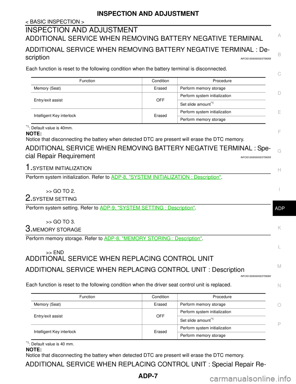
Each function is reset to the following condition when the battery terminal is disconnected.
*1: Default value is 40mm.
NOTE:
Notice that disconnecting the battery when detected DTC are present will erase the DTC memory.
ADDITIONAL SERVICE WHEN REMOVING BATTERY NEGATIVE TERMINAL : Spe-
cial Repair Requirement
INFOID:0000000003759059
1.SYSTEM INITIALIZATION
Perform system initialization. Refer to ADP-8, "
SYSTEM INITIALIZATION : Description".
>> GO TO 2.
2.SYSTEM SETTING
Perform system setting. Refer to ADP-9, "
SYSTEM SETTING : Description".
>> GO TO 3.
3.MEMORY STORAGE
Perform memory storage. Refer to ADP-8, "
MEMORY STORING : Description".
>> END
ADDITIONAL SERVICE WHEN REPLACING CONTROL UNIT
ADDITIONAL SERVICE WHEN REPLACING CONTROL UNIT : Description
INFOID:0000000003759060
Each function is reset to the following condition when the driver seat control unit is replaced.
*1: Default value is 40 mm.
NOTE:
Notice that disconnecting the battery when detected DTC are present will erase the DTC memory.
ADDITIONAL SERVICE WHEN REPLACING CONTROL UNIT : Special Repair Re-
Function Condition Procedure
Memory (Seat) Erased Perform memory storage
Entry/exit assist OFFPerform system initialization
Set slide amount
*1
Intelligent Key interlock ErasedPerform system initialization
Perform memory storage
Function Condition Procedure
Memory (Seat) Erased Perform memory storage
Entry/exit assist OFFPerform system initialization
Set slide amount
*1
Intelligent Key interlock ErasedPerform system initialization
Perform memory storage
Page 14 of 5121
ADP-8
< BASIC INSPECTION >
INSPECTION AND ADJUSTMENT
quirement
INFOID:0000000003759061
1.SYSTEM INITIALIZATION
Perform system initialization. Refer to ADP-8, "
SYSTEM INITIALIZATION : Description".
>> GO TO 2.
2.SYSTEM SETTING
Perform system setting. Refer to ADP-9, "
SYSTEM SETTING : Description".
>> GO TO 3.
3.MEMORY STORAGE
Perform memory storage. Refer to ADP-8, "
MEMORY STORING : Description".
>> END
SYSTEM INITIALIZATION
SYSTEM INITIALIZATION : DescriptionINFOID:0000000003759062
Always perform the initialization when the battery terminal is disconnected or the driver seat control unit is
replaced.
The entry/exit assist function will not operate normally unless initialization is performed.
SYSTEM INITIALIZATION : Special Repair RequirementINFOID:0000000003759063
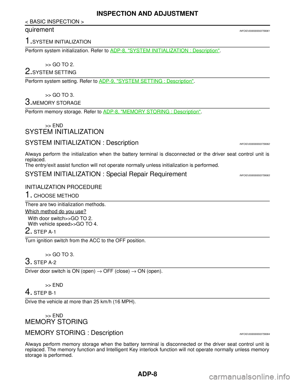
INITIALIZATION PROCEDURE
1. CHOOSE METHOD
There are two initialization methods.
Which method do you use?
With door switch>>GO TO 2.
With vehicle speed>>GO TO 4.
2. STEP A-1
Turn ignition switch from the ACC to the OFF position.
>> GO TO 3.
3. STEP A-2
Driver door switch is ON (open) → OFF (close) → ON (open).
>> END
4. STEP B-1
Drive the vehicle at more than 25 km/h (16 MPH).
>> END
MEMORY STORING
MEMORY STORING : DescriptionINFOID:0000000003759064
Always perform memory storage when the battery terminal is disconnected or the driver seat control unit is
replaced. The memory function and Intelligent Key interlock function will not operate normally unless memory
storage is performed.
Page 15 of 5121
INSPECTION AND ADJUSTMENT
ADP-9
< BASIC INSPECTION >
C
D
E
F
G
H
I
K
L
MA
B
ADP
N
O
P
MEMORY STORING : Special Repair RequirementINFOID:0000000003759065
Memory Storage Procedure
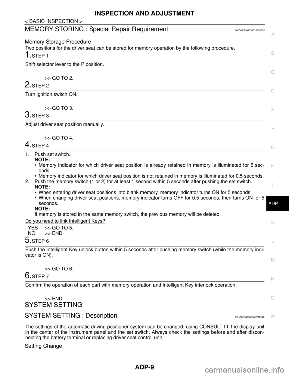
Two positions for the driver seat can be stored for memory operation by the following procedure.
1.STEP 1
Shift selector lever to the P position.
>> GO TO 2.
2.STEP 2
Turn ignition switch ON.
>> GO TO 3.
3.STEP 3
Adjust driver seat position manually.
>> GO TO 4.
4.STEP 4
1. Push set switch.
NOTE:
Memory indicator for which driver seat position is already retained in memory is illuminated for 5 sec-
onds.
Memory indicator for which driver seat position is not retained in memory is illuminated for 0.5 seconds.
2. Push the memory switch (1 or 2) for at least 1 second within 5 seconds after pushing the set switch.
NOTE:
When entering driver seat positions into blank memory, memory indicator turns ON for 5 seconds.
When changing driver seat positions, memory indicator turns OFF for 0.5 seconds, then turns ON for 5
seconds.
NOTE:
If memory is stored in the same memory switch, the previous memory will be deleted.
Do you need to link Intelligent Keys?
YES >> GO TO 5.
NO >> END
5.STEP 6
Push the Intelligent Key unlock button within 5 seconds after pushing memory switch (while the memory indi-
cator is ON).
>> GO TO 6.
6.STEP 7
Confirm the operation of each part with memory operation and Intelligent Key interlock operation.
>> END
SYSTEM SETTING
SYSTEM SETTING : DescriptionINFOID:0000000003759066
The settings of the automatic driving positioner system can be changed, using CONSULT-III, the display unit
in the center of the instrument panel and the set switch. Always check the settings before and after discon-
necting the battery terminal or replacing driver seat control unit.
Setting Change
Page 18 of 5121
ADP-12
< FUNCTION DIAGNOSIS >
AUTOMATIC DRIVE POSITIONER SYSTEM
FUNCTION DIAGNOSIS
AUTOMATIC DRIVE POSITIONER SYSTEM
AUTOMATIC DRIVE POSITIONER SYSTEM
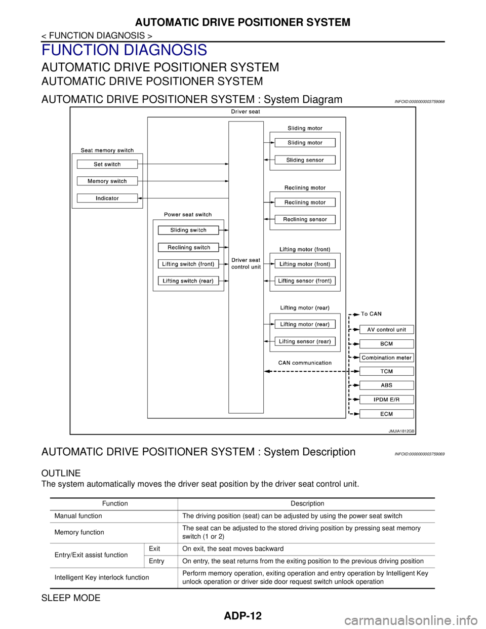
AUTOMATIC DRIVE POSITIONER SYSTEM : System DiagramINFOID:0000000003759068
AUTOMATIC DRIVE POSITIONER SYSTEM : System DescriptionINFOID:0000000003759069
OUTLINE
The system automatically moves the driver seat position by the driver seat control unit.
SLEEP MODE
JMJIA1812GB
Function Description
Manual function The driving position (seat) can be adjusted by using the power seat switch
Memory functionThe seat can be adjusted to the stored driving position by pressing seat memory
switch (1 or 2)
Entry/Exit assist functionExit On exit, the seat moves backward
Entry On entry, the seat returns from the exiting position to the previous driving position
Intelligent Key interlock functionPerform memory operation, exiting operation and entry operation by Intelligent Key
unlock operation or driver side door request switch unlock operation
Page 20 of 5121
ADP-14
< FUNCTION DIAGNOSIS >
AUTOMATIC DRIVE POSITIONER SYSTEM
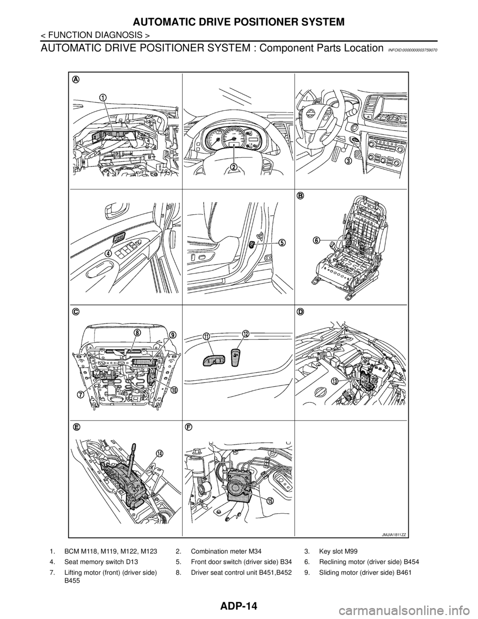
AUTOMATIC DRIVE POSITIONER SYSTEM : Component Parts Location
INFOID:0000000003759070
1. BCM M118, M119, M122, M123 2. Combination meter M34 3. Key slot M99
4. Seat memory switch D13 5. Front door switch (driver side) B34 6. Reclining motor (driver side) B454
7. Lifting motor (front) (driver side)
B4558. Driver seat control unit B451,B452 9. Sliding motor (driver side) B461
JMJIA1811ZZ
Page 21 of 5121

AUTOMATIC DRIVE POSITIONER SYSTEM
ADP-15
< FUNCTION DIAGNOSIS >
C
D
E
F
G
H
I
K
L
MA
B
ADP
N
O
P
AUTOMATIC DRIVE POSITIONER SYSTEM : Component DescriptionINFOID:0000000003759071
CONTROL UNITS
INPUT PARTS
Switches
Sensors
OUTPUT PARTS
10. Lifting motor (rear) (driver side) B456 11. Power seat switch (driver side) B459
(sliding, lifting switch)12. Power seat switch (driver side) B459
(reclining switch)
13. TCM (transmission control module)
F2314. Control device (detention switch)
M5715. ABS actuator and electric unit (con-
trol unit) E36
A. Behind the combination meter B. View with seat cushion and seatback
pad removedC. Back side of the seat cushion
D. Engine room (LH) E. View with the center console assem-
bly removedF. Engine room (RH)
Item Function
Driver seat control unit Main unit of automatic drive positioner system
Connected to the CAN
BCMTransmits the following status to the driver seat control unit via CAN communication
Driver door: OPEN/CLOSE
Ignition switch position: ACC/ON
Door lock: UNLOCK (with Intelligent Key or driver side door request switch oper-
ation)
Key ID
Key switch: Insert/Pull out Intelligent Key
Starter: CRANKING/OTHER
Steering lock unit status: Lock/Unlock
Handle position
Combination meter / ABS actuator and
electric unit (control unit)Transmits the vehicle speed signal to the driver seat control unit via CAN commu-
nication
AV control unit The setting change of auto drive positioner system can be performed on the display
TCMTransmits the shift position signal (P range) to the driver seat control unit via CAN
communication
Item Function
Key slot The key switch is installed to detect the key inserted/removed status
Front door switch (driver side) Detects front door (driver side) open/close status
Control device (detention switch) Detects the P range position of selector lever
Set switch The registration and system setting can be performed with its operation
Memory switch 1/2 The registration and operation can be performed with its operation
Power seat switchThe following switches are installed
Reclining switch
Lifting switch (front)
Lifting switch (rear)
Sliding switch
Item Function
Lifting sensor (front) Detects the up/down position of seat lifting (front)
Lifting sensor (rear) Detects the up/down position of seat lifting (rear)
Reclining sensor Detects the tilt of seatback
Sliding sensor Detects the front/rear position of seat
Page 23 of 5121
AUTOMATIC DRIVE POSITIONER SYSTEM
ADP-17
< FUNCTION DIAGNOSIS >
C
D
E
F
G
H
I
K
L
MA
B
ADP
N
O
P
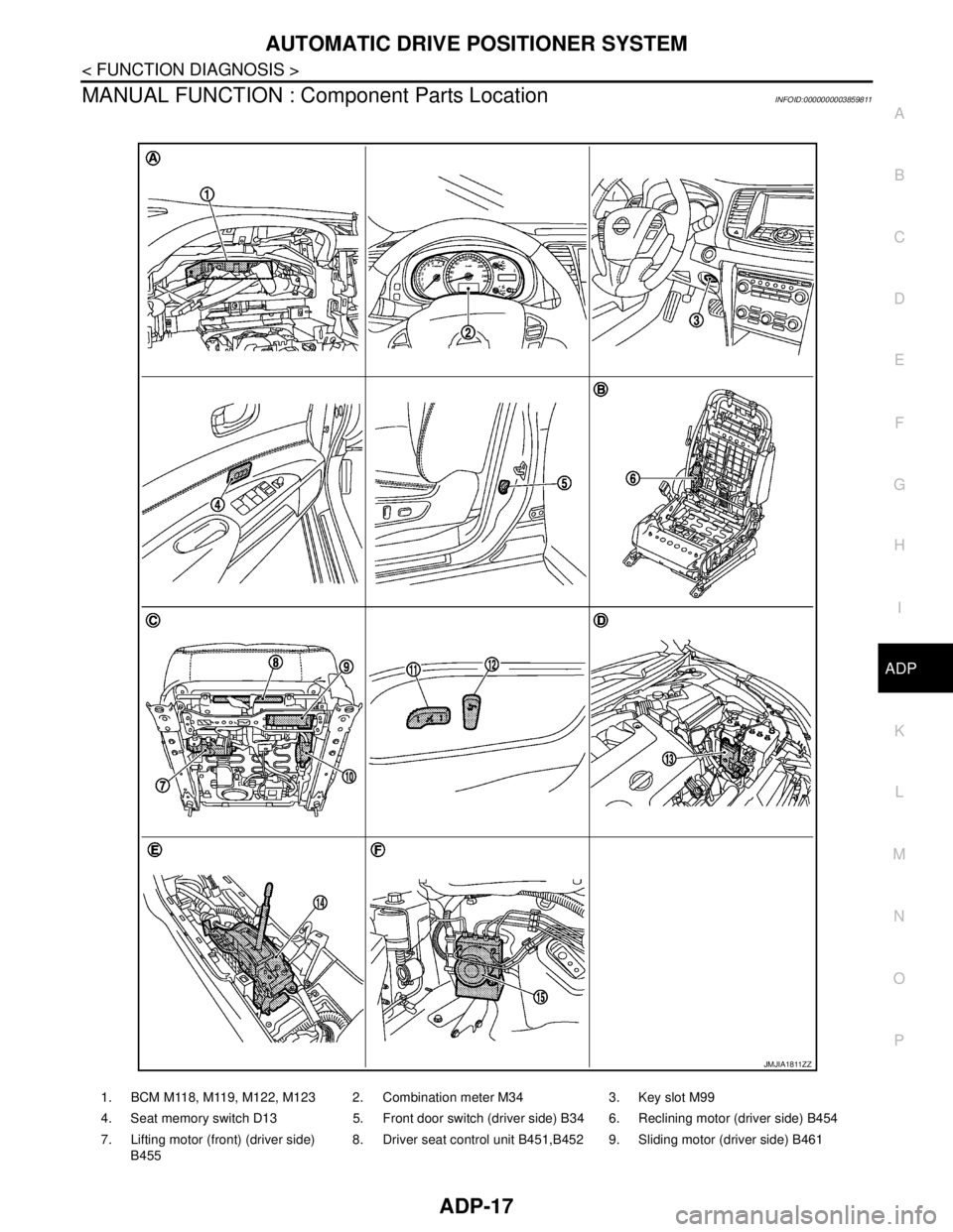
MANUAL FUNCTION : Component Parts LocationINFOID:0000000003859811
1. BCM M118, M119, M122, M123 2. Combination meter M34 3. Key slot M99
4. Seat memory switch D13 5. Front door switch (driver side) B34 6. Reclining motor (driver side) B454
7. Lifting motor (front) (driver side)
B4558. Driver seat control unit B451,B4529.Sliding motor (driver side) B461
JMJIA1811ZZ