run flat NISSAN TEANA 2008 Service Manual
[x] Cancel search | Manufacturer: NISSAN, Model Year: 2008, Model line: TEANA, Model: NISSAN TEANA 2008Pages: 5121, PDF Size: 69.03 MB
Page 836 of 5121
BCS
DIAGNOSIS SYSTEM (BCM)
BCS-19
< FUNCTION DIAGNOSIS >
C
D
E
F
G
H
I
J
K
L B A
O
P N
BUZZER : CONSULT-III Function (BCM - BUZZER)INFOID:0000000003897064
CONSULT-III APPLICATION ITEMS
DATA MONITOR
ACTIVE TEST
INT LAMP
INT LAMP : CONSULT-III Function (BCM - INT LAMP)INFOID:0000000003897059
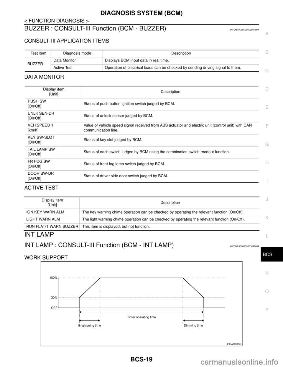
WORK SUPPORT
Test item Diagnosis mode Description
BUZZERData Monitor Displays BCM input data in real time.
Active Test Operation of electrical loads can be checked by sending driving signal to them.
Display item
[Unit]Description
PUSH SW
[On/Off]Status of push button ignition switch judged by BCM.
UNLK SEN-DR
[On/Off]Status of unlock sensor judged by BCM.
VEH SPEED 1
[km/h]Value of vehicle speed signal received from ABS actuator and electric unit (control unit) with CAN
communication line.
KEY SW-SLOT
[On/Off]Status of key slot judged by BCM.
TAIL LAMP SW
[On/Off]Status of each switch judged by BCM using the combination switch readout function.
FR FOG SW
[On/Off]Status of front fog lamp switch judged by BCM.
DOOR SW-DR
[On/Off]Status of driver side door switch judged by BCM.
Display item
[Unit]Description
IGN KEY WARN ALM The key warning chime operation can be checked by operating the relevant function (On/Off).
LIGHT WARN ALM The light warning chime operation can be checked by operating the relevant function (On/Off).
RUN FLAT/T WARN BUZZER This item is displayed, but not function.
JPLIA0093GB
Page 909 of 5121
FRONT DISC BRAKE
BR-13
< ON-VEHICLE MAINTENANCE >
C
D
E
G
H
I
J
K
L
MA
B
BR
N
O
P
FRONT DISC BRAKE
BRAKE PAD
BRAKE PAD : Inspection and AdjustmentINFOID:0000000003811179
INSPECTION
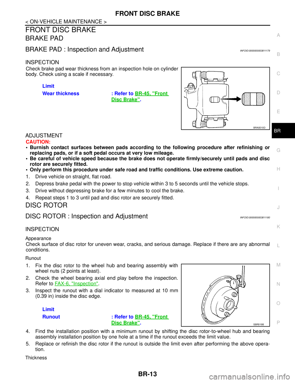
Check brake pad wear thickness from an inspection hole on cylinder
body. Check using a scale if necessary.
ADJUSTMENT
CAUTION:
Burnish contact surfaces between pads according to the following procedure after refinishing or
replacing pads, or if a soft pedal occurs at very low mileage.
Be careful of vehicle speed because the brake does not operate firmly/securely until pads and disc
rotor are securely fitted.
Only perform this procedure under safe road and traffic conditions. Use extreme caution.
1. Drive vehicle on straight, flat road.
2. Depress brake pedal with the power to stop vehicle within 3 to 5 seconds until the vehicle stops.
3. Drive without depressing brake for a few minutes to cool the brake.
4. Repeat steps 1 to 3 until pad and disc rotor are securely fitted.
DISC ROTOR
DISC ROTOR : Inspection and AdjustmentINFOID:0000000003811180
INSPECTION
Appearance
Check surface of disc rotor for uneven wear, cracks, and serious damage. Replace if there are any abnormal
conditions.
Runout
1. Fix the disc rotor to the wheel hub and bearing assembly with
wheel nuts (2 points at least).
2. Check the wheel bearing axial end play before the inspection.
Refer to FA X - 6 , "
Inspection".
3. Inspect the runout with a dial indicator to measured at 10 mm
(0.39 in) inside the disc edge.
4. Find the installation position with a minimum runout by shifting the disc rotor-to-wheel hub and bearing
assembly installation position by one hole at a time if the runout exceeds the limit value.
5. Replace or refinish the disc rotor if the runout is outside the limit even after performing the above opera-
tion.
Thickness
Limit
Wear thickness : Refer to BR-45, "
Front
Disc Brake".
BRA0010D
Limit
Runout : Refer to BR-45, "
Front
Disc Brake".SBR019B
Page 911 of 5121
REAR DISC BRAKE
BR-15
< ON-VEHICLE MAINTENANCE >
C
D
E
G
H
I
J
K
L
MA
B
BR
N
O
P
REAR DISC BRAKE
BRAKE PAD
BRAKE PAD : Inspection and AdjustmentINFOID:0000000003811181
INSPECTION
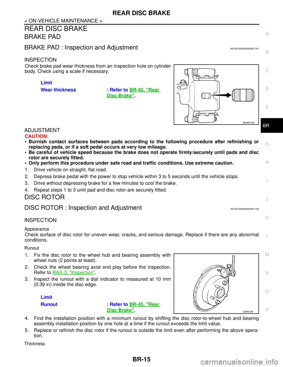
Check brake pad wear thickness from an inspection hole on cylinder
body. Check using a scale if necessary.
ADJUSTMENT
CAUTION:
Burnish contact surfaces between pads according to the following procedure after refinishing or
replacing pads, or if a soft pedal occurs at very low mileage.
Be careful of vehicle speed because the brake does not operate firmly/securely until pads and disc
rotor are securely fitted.
Only perform this procedure under safe road and traffic conditions. Use extreme caution.
1. Drive vehicle on straight, flat road.
2. Depress brake pedal with the power to stop vehicle within 3 to 5 seconds until the vehicle stops.
3. Drive without depressing brake for a few minutes to cool the brake.
4. Repeat steps 1 to 3 until pad and disc rotor are securely fitted.
DISC ROTOR
DISC ROTOR : Inspection and AdjustmentINFOID:0000000003811182
INSPECTION
Appearance
Check surface of disc rotor for uneven wear, cracks, and serious damage. Replace if there are any abnormal
conditions.
Runout
1. Fix the disc rotor to the wheel hub and bearing assembly with
wheel nuts (2 points at least).
2. Check the wheel bearing axial end play before the inspection.
Refer to RAX-3, "
Inspection".
3. Inspect the runout with a dial indicator to measured at 10 mm
(0.39 in) inside the disc edge.
4. Find the installation position with a minimum runout by shifting the disc rotor-to-wheel hub and bearing
assembly installation position by one hole at a time if the runout exceeds the limit value.
5. Replace or refinish the disc rotor if the runout is outside the limit even after performing the above opera-
tion.
Thickness
Limit
Wear thickness : Refer to BR-45, "
Rear
Disc Brake".
BRA0010D
Limit
Runout : Refer to BR-45, "
Rear
Disc Brake".SBR019B
Page 1300 of 5121
![NISSAN TEANA 2008 Service Manual DLK-84
< COMPONENT DIAGNOSIS >[WITH INTELLIGENT KEY SYSTEM]
INTELLIGENT KEY
INTELLIGENT KEY
DescriptionINFOID:0000000003794893
The following functions are available when having and carrying electronic NISSAN TEANA 2008 Service Manual DLK-84
< COMPONENT DIAGNOSIS >[WITH INTELLIGENT KEY SYSTEM]
INTELLIGENT KEY
INTELLIGENT KEY
DescriptionINFOID:0000000003794893
The following functions are available when having and carrying electronic](/img/5/57391/w960_57391-1299.png)
DLK-84
< COMPONENT DIAGNOSIS >[WITH INTELLIGENT KEY SYSTEM]
INTELLIGENT KEY
INTELLIGENT KEY
DescriptionINFOID:0000000003794893
The following functions are available when having and carrying electronic ID.
Door lock/unlock
Trunk lid open
Engine start
Remote control entry function and panic alarm function have specific buttons.
Component Function CheckINFOID:0000000003794894
1.CHECK FUNCTION
Check remote keyless entry receiver (“RKE OPE COUN1”) in Data Monitor mode with CONSULT-III.
Is the inspection result normal?
YES >> Intelligent Key is OK.
NO >> Refer to DLK-84, "
Diagnosis Procedure".
Diagnosis ProcedureINFOID:0000000003794895
1.CHECK INTELLIGENT KEY BATTERY
Check by connecting a resistance (approximately 300 Ω) so that the
current value becomes about 10 mA.
Is the measurement value within the specification?
YES >> Replace Intelligent Key.
NO >> Replace Intelligent Key battery. Refer to DLK-84, "
Com-
ponent Inspection".
Component InspectionINFOID:0000000003794896
1. REPLACE INTELLIGENT KEY BATTERY
1. Release the lock knob at the back of the Intelligent Key and remove the mechanical key.
2. Insert a flat-bladed screwdriver (A) wrapped with a cloth into the
slit of the corner and twist it to separate the upper part from the
lower part.
CAUTION:
Never touch the circuit board or battery terminal.
The key fob is water-resistant. However, if it does get wet,
immediately wipe it dry.
3. Replace the battery with new one.
Monitor item Condition
RKE OPE COUN1 Check that the numerical value is changing while operating on the Intelligent Key.
Standard : Approx. 2.5 - 3.0 V
OCC0607D
PIIB6221E
Page 1434 of 5121
![NISSAN TEANA 2008 Service Manual DLK-218
< ON-VEHICLE REPAIR >[WITH INTELLIGENT KEY SYSTEM]
TRUNK LID
TRUNK LID STAY : Exploded View
INFOID:0000000003819766
TRUNK LID STAY : Removal and InstallationINFOID:0000000003813420
REMOVAL
1. NISSAN TEANA 2008 Service Manual DLK-218
< ON-VEHICLE REPAIR >[WITH INTELLIGENT KEY SYSTEM]
TRUNK LID
TRUNK LID STAY : Exploded View
INFOID:0000000003819766
TRUNK LID STAY : Removal and InstallationINFOID:0000000003813420
REMOVAL
1.](/img/5/57391/w960_57391-1433.png)
DLK-218
< ON-VEHICLE REPAIR >[WITH INTELLIGENT KEY SYSTEM]
TRUNK LID
TRUNK LID STAY : Exploded View
INFOID:0000000003819766
TRUNK LID STAY : Removal and InstallationINFOID:0000000003813420
REMOVAL
1. Support trunk lid with the proper material to prevent it from falling.
WARNING:
Bodily injury may occur if no supporting rod is holding the trunk lid open when removing the trunk
lid stay.
2. Remove the metal clip (3) located on the connection between
the trunk lid stay (1) and the stud ball (2) (trunk lid side) by using
a flat-bladed screwdriver (A).
3. Remove trunk lid stay (trunk lid side).
4. In the same way, remove trunk lid stay (body side).
INSTALLATION
Install in the reverse order of removal.
1. Trunk lid 2. Trunk lid weather-strip 3. Cap
4. Stopper 5. Trunk lid hinge 6. Trunk lid striker
7. Bumper rubber 8. Trunk lid lock assembly 9. Trunk lid stay
A : Center mark (upper) B.: Center mark (lower)
Refer to GI-4, "
Components" for symbols in the figure.
JMKIA2389GB
JMKIA2255ZZ
Page 1963 of 5121
EM-88
< DISASSEMBLY AND ASSEMBLY >
CAMSHAFT
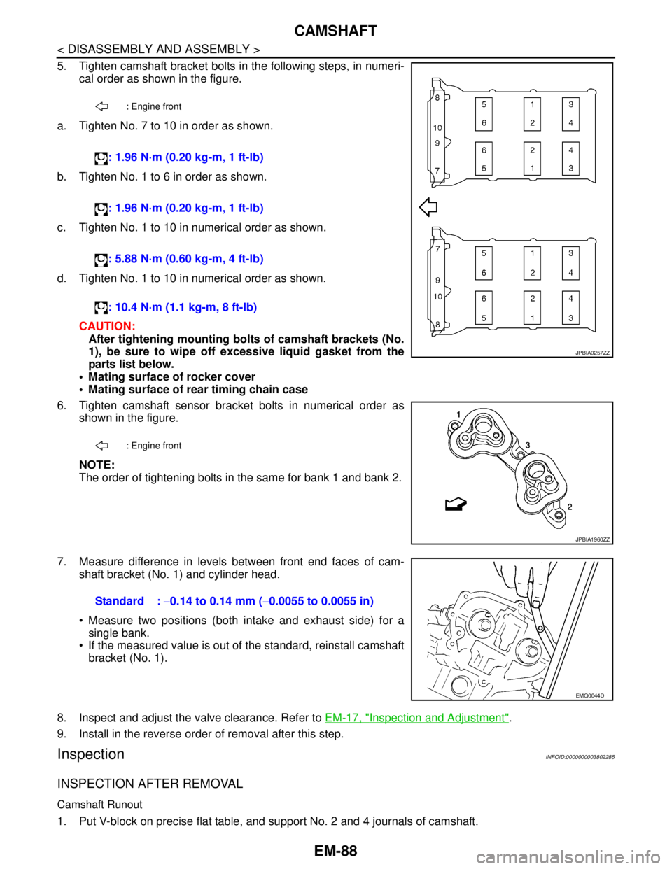
5. Tighten camshaft bracket bolts in the following steps, in numeri-
cal order as shown in the figure.
a. Tighten No. 7 to 10 in order as shown.
b. Tighten No. 1 to 6 in order as shown.
c. Tighten No. 1 to 10 in numerical order as shown.
d. Tighten No. 1 to 10 in numerical order as shown.
CAUTION:
After tightening mounting bolts of camshaft brackets (No.
1), be sure to wipe off excessive liquid gasket from the
parts list below.
Mating surface of rocker cover
Mating surface of rear timing chain case
6. Tighten camshaft sensor bracket bolts in numerical order as
shown in the figure.
NOTE:
The order of tightening bolts in the same for bank 1 and bank 2.
7. Measure difference in levels between front end faces of cam-
shaft bracket (No. 1) and cylinder head.
Measure two positions (both intake and exhaust side) for a
single bank.
If the measured value is out of the standard, reinstall camshaft
bracket (No. 1).
8. Inspect and adjust the valve clearance. Refer to EM-17, "
Inspection and Adjustment".
9. Install in the reverse order of removal after this step.
InspectionINFOID:0000000003802285
INSPECTION AFTER REMOVAL
Camshaft Runout
1. Put V-block on precise flat table, and support No. 2 and 4 journals of camshaft.
: Engine front
: 1.96 N·m (0.20 kg-m, 1 ft-lb)
: 1.96 N·m (0.20 kg-m, 1 ft-lb)
: 5.88 N·m (0.60 kg-m, 4 ft-lb)
: 10.4 N·m (1.1 kg-m, 8 ft-lb)
: Engine front
JPBIA0257ZZ
JPBIA1960ZZ
Standard : −0.14 to 0.14 mm (−0.0055 to 0.0055 in)
EMQ0044D
Page 1965 of 5121
EM-90
< DISASSEMBLY AND ASSEMBLY >
CAMSHAFT
If the calculated value exceeds the limit, replace either or both camshaft and cylinder head.
NOTE:
Camshaft brackets cannot be replaced as single parts, because there are machined together with cylinder
head. Replace whole cylinder head assembly.
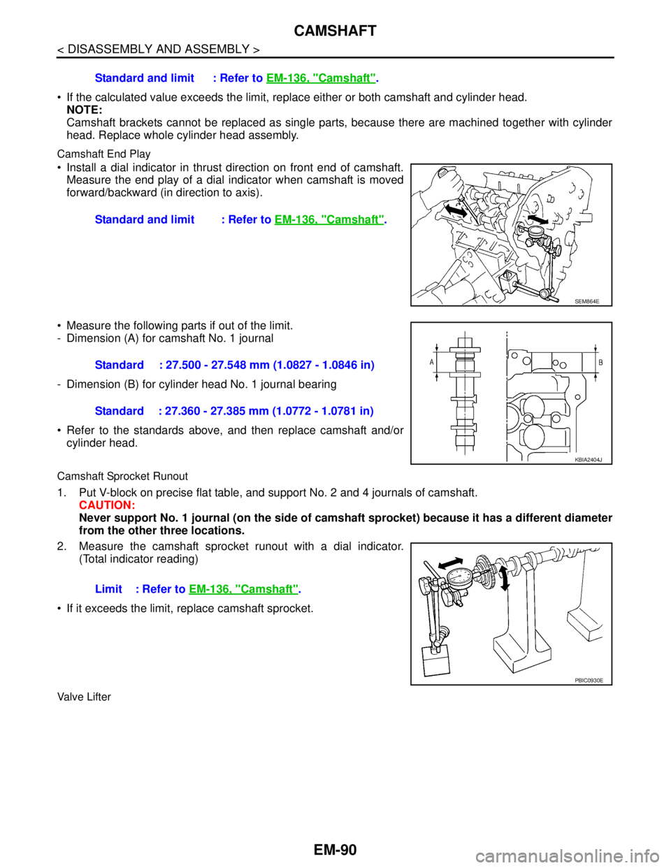
Camshaft End Play
Install a dial indicator in thrust direction on front end of camshaft.
Measure the end play of a dial indicator when camshaft is moved
forward/backward (in direction to axis).
Measure the following parts if out of the limit.
- Dimension (A) for camshaft No. 1 journal
- Dimension (B) for cylinder head No. 1 journal bearing
Refer to the standards above, and then replace camshaft and/or
cylinder head.
Camshaft Sprocket Runout
1. Put V-block on precise flat table, and support No. 2 and 4 journals of camshaft.
CAUTION:
Never support No. 1 journal (on the side of camshaft sprocket) because it has a different diameter
from the other three locations.
2. Measure the camshaft sprocket runout with a dial indicator.
(Total indicator reading)
If it exceeds the limit, replace camshaft sprocket.
Valve Lifter
Standard and limit : Refer to EM-136, "Camshaft".
Standard and limit : Refer to EM-136, "
Camshaft".
SEM864E
Standard : 27.500 - 27.548 mm (1.0827 - 1.0846 in)
Standard : 27.360 - 27.385 mm (1.0772 - 1.0781 in)
KBIA2404J
Limit : Refer to EM-136, "Camshaft".
PBIC0930E
Page 2000 of 5121
CYLINDER BLOCK
EM-125
< DISASSEMBLY AND ASSEMBLY >
C
D
E
F
G
H
I
J
K
L
MA
EM
N
P O
If out of the standard, measure the main bearing oil clearance. Then use undersize bearing. Refer to EM-
132, "MainBearing".
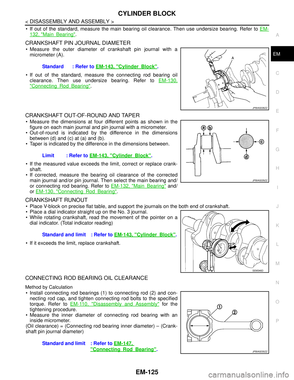
CRANKSHAFT PIN JOURNAL DIAMETER
Measure the outer diameter of crankshaft pin journal with a
micrometer (A).
If out of the standard, measure the connecting rod bearing oil
clearance. Then use undersize bearing. Refer to EM-130,
"ConnectingRodBearing".
CRANKSHAFT OUT-OF-ROUND AND TAPER
Measure the dimensions at four different points as shown in the
figure on each main journal and pin journal with a micrometer.
Out-of-round is indicated by the difference in the dimensions
between (d) and (c) at (a) and (b).
Taper is indicated by the difference in the dimensions between.
If the measured value exceeds the limit, correct or replace crank-
shaft.
If corrected, measure the bearing oil clearance of the corrected
main journal and/or pin journal. Then select the main bearing and/
or connecting rod bearing. Refer to EM-132, "
MainBearing" and/
or EM-130, "
ConnectingRodBearing".
CRANKSHAFT RUNOUT
Place V-block on precise flat table, and support the journals on the both end of crankshaft.
Place a dial indicator straight up on the No. 3 journal.
While rotating crankshaft, read the movement of the pointer on a
dial indicator. (Total indicator reading)
If it exceeds the limit, replace crankshaft.
CONNECTING ROD BEARING OIL CLEARANCE
Method by Calculation
Install connecting rod bearings (1) to connecting rod (2) and con-
necting rod cap, and tighten connecting rod bolts to the specified
torque. Refer to EM-110, "
Disassembly and Assembly" for the
tightening procedure.
Measure the inner diameter of connecting rod bearing with an
inside micrometer.
(Oil clearance) = (Connecting rod bearing inner diameter) – (Crank-
shaft pin journal diameter)Standard : Refer to EM-143, "
CylinderBlock".
JPBIA0228ZZ
Limit : Refer to EM-143, "CylinderBlock".
JPBIA0229ZZ
Standard and limit : Refer to EM-143, "CylinderBlock".
SEM346D
Standard and limit : Refer to EM-147,
"ConnectingRodBearing".JPBIA0230ZZ
Page 3838 of 5121
RSU-6
< ON-VEHICLE MAINTENANCE >
WHEEL ALIGNMENT
WHEEL ALIGNMENT
InspectionINFOID:0000000003813442
DESCRIPTION
Measure wheel alignment under unladen conditions.
NOTE:
“Unladen conditions” means that fuel, engine coolant, and lubricant are full. Spare tire, jack, hand tools and
mats are in designated positions.
PRELIMINARY CHECK
Check the following:
Tires for improper air pressure and wear
Road wheels for runout: refer to WT-2, "
Inspection".
Wheel bearing axial end play: refer to RAX-3, "
Inspection".
Shock absorber operation
Each mounting point of axle and suspension for looseness and deformation
Each of lower link, upper link, rear suspension member, suspension arm and shock absorber for cracks,
deformation, and other damage
Vehicle height (posture)
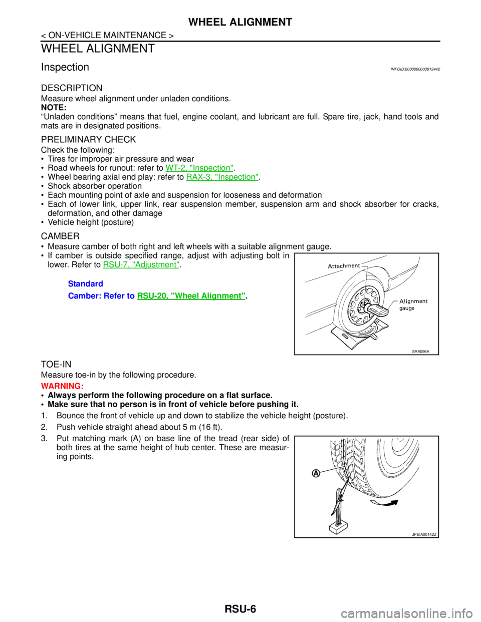
CAMBER
Measure camber of both right and left wheels with a suitable alignment gauge.
If camber is outside specified range, adjust with adjusting bolt in
lower. Refer to RSU-7, "
Adjustment".
TOE-IN
Measure toe-in by the following procedure.
WARNING:
Always perform the following procedure on a flat surface.
Make sure that no person is in front of vehicle before pushing it.
1. Bounce the front of vehicle up and down to stabilize the vehicle height (posture).
2. Push vehicle straight ahead about 5 m (16 ft).
3. Put matching mark (A) on base line of the tread (rear side) of
both tires at the same height of hub center. These are measur-
ing points.Standard
Camber: Refer to RSU-20, "
Wheel Alignment".
SRA096A
JPEIA0014ZZ
Page 4948 of 5121
![NISSAN TEANA 2008 Service Manual WCS-18
< FUNCTION DIAGNOSIS >
DIAGNOSIS SYSTEM (BCM)
ACTIVE TEST
Display item
[Unit]Description
PUSH SW
[On/Off]Status of push button ignition switch judged by BCM.
UNLK SEN-DR
[On/Off]Status of unloc NISSAN TEANA 2008 Service Manual WCS-18
< FUNCTION DIAGNOSIS >
DIAGNOSIS SYSTEM (BCM)
ACTIVE TEST
Display item
[Unit]Description
PUSH SW
[On/Off]Status of push button ignition switch judged by BCM.
UNLK SEN-DR
[On/Off]Status of unloc](/img/5/57391/w960_57391-4947.png)
WCS-18
< FUNCTION DIAGNOSIS >
DIAGNOSIS SYSTEM (BCM)
ACTIVE TEST
Display item
[Unit]Description
PUSH SW
[On/Off]Status of push button ignition switch judged by BCM.
UNLK SEN-DR
[On/Off]Status of unlock sensor judged by BCM.
VEH SPEED 1
[km/h]Value of vehicle speed signal received from ABS actuator and electric unit (control unit) with CAN
communication line.
KEY SW-SLOT
[On/Off]Status of key slot judged by BCM.
TA I L L A M P S W
[On/Off]Status of each switch judged by BCM using the combination switch readout function.
FR FOG SW
[On/Off]Status of front fog lamp switch judged by BCM.
DOOR SW-DR
[On/Off]Status of driver side door switch judged by BCM.
Display item
[Unit]Description
IGN KEY WARN ALM The key warning chime operation can be checked by operating the relevant function (On/Off).
LIGHT WARN ALM The light warning chime operation can be checked by operating the relevant function (On/Off).
RUN FLAT/T WARN BUZZER This item is displayed, but not function.