mirror NISSAN TEANA 2008 Service Manual
[x] Cancel search | Manufacturer: NISSAN, Model Year: 2008, Model line: TEANA, Model: NISSAN TEANA 2008Pages: 5121, PDF Size: 69.03 MB
Page 1 of 5121

MODEL J32 SERIES
© 2008 NISSAN INTERNATIONAL SA
Allrightsreserved.NopartofthisElectronicServiceManualmaybereproducedorstoredinaretrievalsystem,ortransmittedinanyform,or by any means, electronic, mechanical, photocopying, recording or otherwise, without the prior written permission of Nissan InternationalSA, Switzerland.
AGENERALINFORMATION
BENGINE
DTRANSMISSION&DRIVELINE
ESUSPENSION
FBRAKES
GSTEERING
HRESTRAINTS
IVENTILATION,HEATER&AIRCONDITIONER
JBODYINTERIOR
KBODYEXTERIOR,DOOR,ROOF&VEHICLESECURITY
LDRIVERCONTROLS
MELECTRICAL&POWERCONTROL
NDRIVERINFORMATION&MULTIMEDIA
PMAINTENANCE
GIGeneralInformation
EMEngineMechanical
LUEngineLubricationSystem
COEngineCoolingSystem
ECEngineControlSystem
FLFuelSystem
EXExhaustSystem
STRStartingSystem
ACCAcceleratorControlSystem
TMTransaxle &Transmission
FAXFrontAxle
RAXRearAxle
FSUFrontSuspension
RSURearSuspension
WTRoadWheels &Tires
BRBrakeSystem
PBParkingBrakeSystem
BRCBrakeControlSystem
STSteeringSystem
STCSteeringControlSystem
SBSeatBelt
SRSRSAirbag
SRCSRSAirbagControlSystem
VTLVentilationSystem
HAHeater &AirConditioningSystem
HACHeater &AirConditioningControlSystem
INTInterior
IPInstrumentPanel
SESeat
ADPAutomaticDrivePositioner
DLKDoor &Lock
SECSecurityControlSystem
GWGlass &WindowSystem
PWCPowerWindowControlSystem
RFRoof
EXTExterior
MIRMirrors
EXLExteriorLightingSystem
INLInteriorLightingSystem
WWWiper &Washer
DEFDefogger
HRNHorn
PWOPowerOutlet
BCSBodyControlSystem
LANLANSystem
PCSPowerControlSystem
CHGChargingSystem
PGPowerSupply,Ground&CircuitElements
MWIMeter,WarningLamp&Indicator
WCSWarningChimeSystem
AVAudio,Visual&NavigationSystem
MAMaintenance
QUICKREFERENCEINDEX
A
B
C
D
E
F
G
H
I
J
K
L
M
N
O
P
M
Publication Number:
SM8E00-1J32E0E
Page 998 of 5121
![NISSAN TEANA 2008 Service Manual WHEEL SENSOR
BRC-57
< ON-VEHICLE REPAIR >[ABS]
C
D
E
G
H
I
J
K
L
MA
B
BRC
N
O
P
ON-VEHICLE REPAIR
WHEEL SENSOR
FRONT WHEEL SENSOR
FRONT WHEEL SENSOR : Exploded ViewINFOID:0000000003766865
NOTE:
The ab NISSAN TEANA 2008 Service Manual WHEEL SENSOR
BRC-57
< ON-VEHICLE REPAIR >[ABS]
C
D
E
G
H
I
J
K
L
MA
B
BRC
N
O
P
ON-VEHICLE REPAIR
WHEEL SENSOR
FRONT WHEEL SENSOR
FRONT WHEEL SENSOR : Exploded ViewINFOID:0000000003766865
NOTE:
The ab](/img/5/57391/w960_57391-997.png)
WHEEL SENSOR
BRC-57
< ON-VEHICLE REPAIR >[ABS]
C
D
E
G
H
I
J
K
L
MA
B
BRC
N
O
P
ON-VEHICLE REPAIR
WHEEL SENSOR
FRONT WHEEL SENSOR
FRONT WHEEL SENSOR : Exploded ViewINFOID:0000000003766865
NOTE:
The above figure shows left side. Right side is the mirror image.
FRONT WHEEL SENSOR : Removal and InstallationINFOID:0000000003766866
REMOVAL
Be careful with the following when removing sensor.
CAUTION:
Do not twist sensor harness as much as possible, when removing it. Pull sensors out without pulling
sensor harness.
Be careful to avoid damaging sensor edges or rotor teeth. Remove wheel sensor first before remov-
ing front or rear wheel hub. This is to avoid damage to sensor wiring and loss of sensor function.
INSTALLATION
Be careful with the following when installing wheel sensor. Tighten installation bolts to the specified torques.
Refer to BRC-57, "
FRONT WHEEL SENSOR : Exploded View".
CAUTION:
When installing, make sure there is no foreign material such as iron chips on and in the mounting
hole of the wheel sensor. Make sure no foreign material has been caught in the sensor rotor. Remove
any foreign material and clean the mount.
1. Front LH wheel sensor 2. Front LH wheel sensor connector
: Vehicle front
Refer to GI section GI-4, "
Components" for symbol marks in the figure.
JSFIA0221GB
Page 999 of 5121
![NISSAN TEANA 2008 Service Manual BRC-58
< ON-VEHICLE REPAIR >[ABS]
WHEEL SENSOR
Completely push in rubber grommets of strut bracket and body bracket until they lock when install-
ing wheel sensor so that the wheel sensor harness wi NISSAN TEANA 2008 Service Manual BRC-58
< ON-VEHICLE REPAIR >[ABS]
WHEEL SENSOR
Completely push in rubber grommets of strut bracket and body bracket until they lock when install-
ing wheel sensor so that the wheel sensor harness wi](/img/5/57391/w960_57391-998.png)
BRC-58
< ON-VEHICLE REPAIR >[ABS]
WHEEL SENSOR
Completely push in rubber grommets of strut bracket and body bracket until they lock when install-
ing wheel sensor so that the wheel sensor harness will not be twisted. Install grommet groove onto
bracket with orange line on the harness facing bracket opening (mounting hole). There should be no
twists in the harness when installed.
REAR WHEEL SENSOR
REAR WHEEL SENSOR : Exploded ViewINFOID:0000000003766867
NOTE:
The above figure shows left side. Right side is the mirror image.
REAR WHEEL SENSOR : Removal and InstallationINFOID:0000000003766868
REMOVAL
Be careful with the following when removing sensor.
CAUTION:
Do not twist sensor harness as much as possible, when removing it. Pull sensors out without pulling
sensor harness.
Be careful to avoid damaging sensor edges or rotor teeth. Remove wheel sensor first before remov-
ing front or rear wheel hub. This is to avoid damage to sensor wiring and loss of sensor function.
INSTALLATION
Be careful with the following when installing wheel sensor. Tighten installation bolts to the specified torques.
Refer to BRC-58, "
REAR WHEEL SENSOR : Exploded View".
CAUTION:
When installing, make sure there is no foreign material such as iron chips on and in the mounting hole
of the wheel sensor. Make sure no foreign material has been caught in the sensor rotor. Remove any
foreign material and clean the mount.
1. Rear LH wheel sensor connector 2. Rear LH wheel sensor
: Vehicle front
Refer to GI section GI-4, "
Components" for symbol marks in the figure.
JSFIA0222GB
Page 1092 of 5121
![NISSAN TEANA 2008 Service Manual WHEEL SENSOR
BRC-151
< ON-VEHICLE REPAIR >[VDC/TCS/ABS]
C
D
E
G
H
I
J
K
L
MA
B
BRC
N
O
P
ON-VEHICLE REPAIR
WHEEL SENSOR
FRONT WHEEL SENSOR
FRONT WHEEL SENSOR : Exploded ViewINFOID:0000000003767300
NOT NISSAN TEANA 2008 Service Manual WHEEL SENSOR
BRC-151
< ON-VEHICLE REPAIR >[VDC/TCS/ABS]
C
D
E
G
H
I
J
K
L
MA
B
BRC
N
O
P
ON-VEHICLE REPAIR
WHEEL SENSOR
FRONT WHEEL SENSOR
FRONT WHEEL SENSOR : Exploded ViewINFOID:0000000003767300
NOT](/img/5/57391/w960_57391-1091.png)
WHEEL SENSOR
BRC-151
< ON-VEHICLE REPAIR >[VDC/TCS/ABS]
C
D
E
G
H
I
J
K
L
MA
B
BRC
N
O
P
ON-VEHICLE REPAIR
WHEEL SENSOR
FRONT WHEEL SENSOR
FRONT WHEEL SENSOR : Exploded ViewINFOID:0000000003767300
NOTE:
The above figure shows left side. Right side is the mirror image.
FRONT WHEEL SENSOR : Removal and InstallationINFOID:0000000003767301
REMOVAL
Be careful with the following when removing sensor.
CAUTION:
Do not twist sensor harness as much as possible, when removing it. Pull sensors out without pulling
sensor harness.
Be careful to avoid damaging sensor edges or rotor teeth. Remove wheel sensor first before remov-
ing front or rear wheel hub. This is to avoid damage to sensor wiring and loss of sensor function.
INSTALLATION
Be careful with the following when installing wheel sensor. Tighten installation bolts to the specified torques.
Refer to BRC-151, "
FRONT WHEEL SENSOR : Exploded View".
CAUTION:
When installing, make sure there is no foreign material such as iron chips on and in the mounting
hole of the wheel sensor. Make sure no foreign material has been caught in the sensor rotor. Remove
any foreign material and clean the mount.
1. Front LH wheel sensor 2. Front LH wheel sensor connector
: Vehicle front
Refer to GI section GI-4, "
Components" for symbol marks in the figure.
JSFIA0221GB
Page 1093 of 5121
![NISSAN TEANA 2008 Service Manual BRC-152
< ON-VEHICLE REPAIR >[VDC/TCS/ABS]
WHEEL SENSOR
Completely push in rubber grommets of strut bracket and body bracket until they lock when install-
ing wheel sensor so that the wheel sensor h NISSAN TEANA 2008 Service Manual BRC-152
< ON-VEHICLE REPAIR >[VDC/TCS/ABS]
WHEEL SENSOR
Completely push in rubber grommets of strut bracket and body bracket until they lock when install-
ing wheel sensor so that the wheel sensor h](/img/5/57391/w960_57391-1092.png)
BRC-152
< ON-VEHICLE REPAIR >[VDC/TCS/ABS]
WHEEL SENSOR
Completely push in rubber grommets of strut bracket and body bracket until they lock when install-
ing wheel sensor so that the wheel sensor harness will not be twisted. Install grommet groove onto
bracket with orange line on the harness facing bracket opening (mounting hole). There should be no
twists in the harness when installed.
REAR WHEEL SENSOR
REAR WHEEL SENSOR : Exploded ViewINFOID:0000000003767302
NOTE:
The above figure shows left side. Right side is the mirror image.
REAR WHEEL SENSOR : Removal and InstallationINFOID:0000000003767303
REMOVAL
Be careful with the following when removing sensor.
CAUTION:
Do not twist sensor harness as much as possible, when removing it. Pull sensors out without pulling
sensor harness.
Be careful to avoid damaging sensor edges or rotor teeth. Remove wheel sensor first before remov-
ing front or rear wheel hub. This is to avoid damage to sensor wiring and loss of sensor function.
INSTALLATION
Be careful with the following when installing wheel sensor. Tighten installation bolts to the specified torques.
Refer to BRC-152, "
REAR WHEEL SENSOR : Exploded View".
CAUTION:
When installing, make sure there is no foreign material such as iron chips on and in the mounting hole
of the wheel sensor. Make sure no foreign material has been caught in the sensor rotor. Remove any
foreign material and clean the mount.
1. Rear LH wheel sensor connector 2. Rear LH wheel sensor
: Vehicle front
Refer to GI section GI-4, "
Components" for symbol marks in the figure.
JSFIA0222GB
Page 1151 of 5121

DEF-1
DRIVER CONTROLS
C
D
E
F
G
H
I
J
K
M
SECTION DEF
A
B
DEF
N
O
P
CONTENTS
DEFOGGER
BASIC INSPECTION ....................................3
DIAGNOSIS AND REPAIR WORKFLOW ..........3
Work Flow .................................................................3
FUNCTION DIAGNOSIS ...............................4
REAR WINDOW DEFOGGER SYSTEM .............4
WITH AV CONTROL UNIT ..........................................4
WITH AV CONTROL UNIT : System Diagram ..........4
WITH AV CONTROL UNIT : System Description ......4
WITH AV CONTROL UNIT : Component Parts Lo-
cation .........................................................................
5
WITH AV CONTROL UNIT : Component Descrip-
tion ............................................................................
5
WITHOUT AV CONTROL UNIT ..................................6
WITHOUT AV CONTROL UNIT : System Diagram
......
6
WITHOUT AV CONTROL UNIT : System Descrip-
tion ............................................................................
6
WITHOUT AV CONTROL UNIT : Component
Parts Location ...........................................................
7
WITHOUT AV CONTROL UNIT : Component De-
scription .....................................................................
7
DIAGNOSIS SYSTEM (BCM) .............................8
COMMON ITEM ...........................................................8
COMMON ITEM : CONSULT-III Function (BCM -
COMMON ITEM) .......................................................
8
REAR WINDOW DEFOGGER .....................................9
REAR WINDOW DEFOGGER : CONSULT-III
Function (BCM - REAR DEFOGGER) ......................
9
COMPONENT DIAGNOSIS .........................11
POWER SUPPLY AND GROUND CIRCUIT ......11
Diagnosis Procedure ...............................................11
REAR WINDOW DEFOGGER SWITCH ............12
WITH AV CONTROL UNIT ........................................12
WITH AV CONTROL UNIT : Description .................12
WITH AV CONTROL UNIT : Component Function
Check ......................................................................
12
WITH AV CONTROL UNIT : Diagnosis Procedure ....12
WITHOUT AV CONTROL UNIT .................................12
WITHOUT AV CONTROL UNIT : Description .........12
WITHOUT AV CONTROL UNIT : Component
Function Check ........................................................
12
WITHOUT AV CONTROL UNIT : Diagnosis Pro-
cedure ......................................................................
12
REAR WINDOW DEFOGGER RELAY .............14
Description ...............................................................14
Component Function Check ....................................14
Diagnosis Procedure ...............................................14
Component Inspection .............................................15
REAR WINDOW DEFOGGER ..........................16
Description ...............................................................16
Component Function Check ....................................16
Diagnosis Procedure ...............................................16
Component Inspection .............................................18
DOOR MIRROR DEFOGGER ...........................19
Description ...............................................................19
Component Function Check ....................................19
Diagnosis Procedure ...............................................19
DRIVER SIDE DOOR MIRROR DEFOGGER ...21
Description ...............................................................21
Component Function Check ....................................21
Diagnosis Procedure ...............................................21
PASSENGER SIDE DOOR MIRROR DEFOG-
GER ...................................................................
23
Description ...............................................................23
Component Function Check ....................................23
Diagnosis Procedure ...............................................23
REAR WINDOW DEFOGGER ON SIGNAL .....25
Page 1152 of 5121

DEF-2
Description ..............................................................25
Component Function Check ...................................25
Diagnosis Procedure ..............................................25
ECU DIAGNOSIS ........................................26
BCM (BODY CONTROL MODULE) ..................26
Reference Value .....................................................26
Wiring Diagram - DEFOGGER SYSTEM - .............49
Fail-safe ..................................................................53
DTC Inspection Priority Chart ..............................55
DTC Index ..............................................................56
SYMPTOM DIAGNOSIS .............................58
REAR WINDOW DEFOGGER AND DOOR
MIRROR DEFOGGER DO NOT OPERATE. .....
58
Diagnosis Procedure ..............................................58
REAR WINDOW DEFOGGER DOES NOT
OPERATE BUT BOTH DOOR MIRROR DE-
FOGGERS OPERATE. ......................................
59
Diagnosis Procedure ..............................................59
DOOR MIRROR DEFOGGER DOES NOT OP-
ERATE ...............................................................
60
BOTH SIDES .............................................................60
BOTH SIDES : Diagnosis Procedure .....................60
DRIVER SIDE ............................................................60
DRIVER SIDE : Diagnosis Procedure ....................60
PASSENGER SIDE ...................................................60
PASSENGER SIDE : Diagnosis Procedure ...........60
ON IS NOT DISPLAYED WHEN PRESSING
REAR WINDOW DEFOGGER SWITCH BUT
IT OPERATES ...................................................
61
WITH AV CONTROL UNIT ........................................61
WITH AV CONTROL UNIT : Diagnosis Procedure ...61
WITHOUT AV CONTROL UNIT ................................61
WITHOUT AV CONTROL UNIT : Diagnosis Pro-
cedure .....................................................................
61
REAR WINDOW DEFOGGER INDICATOR
DOES NOT ILLUMINATE ..................................
62
WITH AV CONTROL UNIT ........................................62
WITH AV CONTROL UNIT : Diagnosis Procedure ...62
WITHOUT AV CONTROL UNIT ................................62
WITHOUT AV CONTROL UNIT : Diagnosis Pro-
cedure .....................................................................
62
PRECAUTION ............................................63
PRECAUTIONS .................................................63
Precaution for Supplemental Restraint System
(SRS) "AIR BAG" and "SEAT BELT PRE-TEN-
SIONER" .................................................................
63
ON-VEHICLE REPAIR ...............................64
FILAMENT .........................................................64
Inspection and Repair .............................................64
CONDENSER ....................................................66
Exploded View ........................................................66
Removal and Installation .........................................66
Page 1154 of 5121

DEF-4
< FUNCTION DIAGNOSIS >
REAR WINDOW DEFOGGER SYSTEM
FUNCTION DIAGNOSIS
REAR WINDOW DEFOGGER SYSTEM
WITH AV CONTROL UNIT
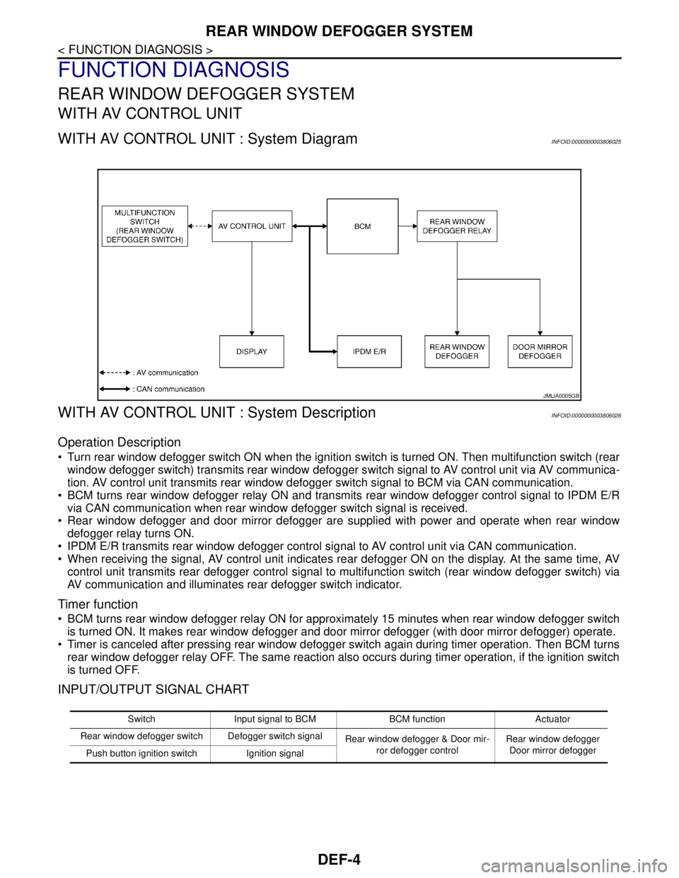
WITH AV CONTROL UNIT : System DiagramINFOID:0000000003806025
WITH AV CONTROL UNIT : System DescriptionINFOID:0000000003806026
Operation Description
Turn rear window defogger switch ON when the ignition switch is turned ON. Then multifunction switch (rear
window defogger switch) transmits rear window defogger switch signal to AV control unit via AV communica-
tion. AV control unit transmits rear window defogger switch signal to BCM via CAN communication.
BCM turns rear window defogger relay ON and transmits rear window defogger control signal to IPDM E/R
via CAN communication when rear window defogger switch signal is received.
Rear window defogger and door mirror defogger are supplied with power and operate when rear window
defogger relay turns ON.
IPDM E/R transmits rear window defogger control signal to AV control unit via CAN communication.
When receiving the signal, AV control unit indicates rear defogger ON on the display. At the same time, AV
control unit transmits rear defogger control signal to multifunction switch (rear window defogger switch) via
AV communication and illuminates rear defogger switch indicator.
Timer function
BCM turns rear window defogger relay ON for approximately 15 minutes when rear window defogger switch
is turned ON. It makes rear window defogger and door mirror defogger (with door mirror defogger) operate.
Timer is canceled after pressing rear window defogger switch again during timer operation. Then BCM turns
rear window defogger relay OFF. The same reaction also occurs during timer operation, if the ignition switch
is turned OFF.
INPUT/OUTPUT SIGNAL CHART
JMLIA0005GB
Switch Input signal to BCM BCM function Actuator
Rear window defogger switch Defogger switch signal
Rear window defogger & Door mir-
ror defogger controlRear window defogger
Door mirror defogger
Push button ignition switch Ignition signal
Page 1155 of 5121

REAR WINDOW DEFOGGER SYSTEM
DEF-5
< FUNCTION DIAGNOSIS >
C
D
E
F
G
H
I
J
K
MA
B
DEF
N
O
P
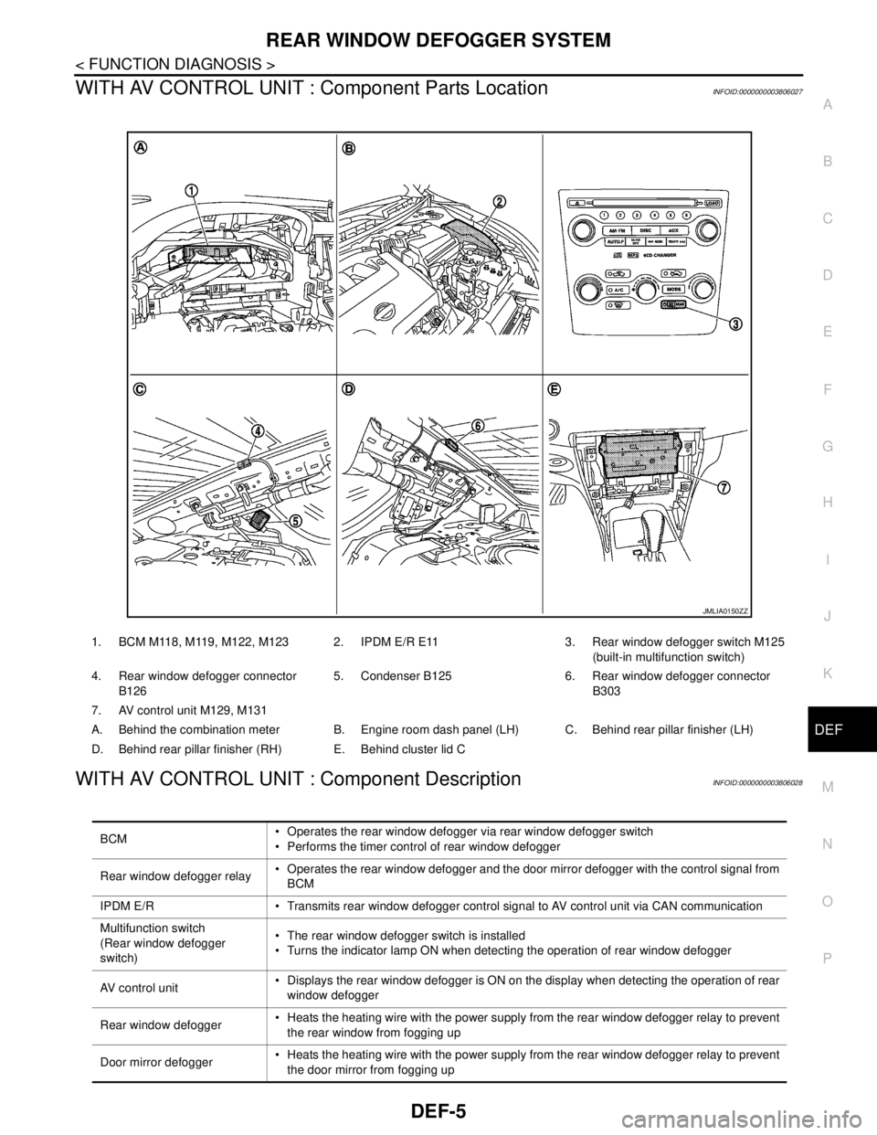
WITH AV CONTROL UNIT : Component Parts LocationINFOID:0000000003806027
WITH AV CONTROL UNIT : Component DescriptionINFOID:0000000003806028
1. BCM M118, M119, M122, M123 2. IPDM E/R E11 3. Rear window defogger switch M125
(built-in multifunction switch)
4. Rear window defogger connector
B1265. Condenser B125 6. Rear window defogger connector
B303
7. AV control unit M129, M131
A. Behind the combination meter B. Engine room dash panel (LH) C. Behind rear pillar finisher (LH)
D. Behind rear pillar finisher (RH) E. Behind cluster lid C
JMLIA0150ZZ
BCM Operates the rear window defogger via rear window defogger switch
Performs the timer control of rear window defogger
Rear window defogger relay Operates the rear window defogger and the door mirror defogger with the control signal from
BCM
IPDM E/R Transmits rear window defogger control signal to AV control unit via CAN communication
Multifunction switch
(Rear window defogger
switch) The rear window defogger switch is installed
Turns the indicator lamp ON when detecting the operation of rear window defogger
AV control unit Displays the rear window defogger is ON on the display when detecting the operation of rear
window defogger
Rear window defogger Heats the heating wire with the power supply from the rear window defogger relay to prevent
the rear window from fogging up
Door mirror defogger Heats the heating wire with the power supply from the rear window defogger relay to prevent
the door mirror from fogging up
Page 1156 of 5121

DEF-6
< FUNCTION DIAGNOSIS >
REAR WINDOW DEFOGGER SYSTEM
WITHOUT AV CONTROL UNIT
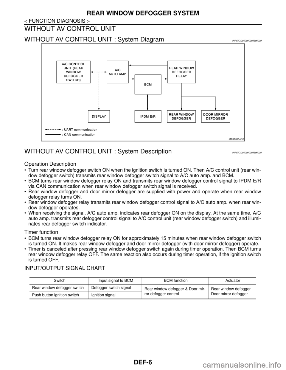
WITHOUT AV CONTROL UNIT : System DiagramINFOID:0000000003806029
WITHOUT AV CONTROL UNIT : System DescriptionINFOID:0000000003806030
Operation Description
Turn rear window defogger switch ON when the ignition switch is turned ON. Then A/C control unit (rear win-
dow defogger switch) transmits rear window defogger switch signal to A/C auto amp. and BCM.
BCM turns rear window defogger relay ON and transmits rear window defogger control signal to IPDM E/R
via CAN communication when rear window defogger switch signal is received.
Rear window defogger and door mirror defogger are supplied with power and operate when rear window
defogger relay turns ON.
Rear window defogger relay transmits rear window defogger control signal to A/C auto amp. when rear win-
dow defogger operates.
When receiving the signal, A/C auto amp. indicates rear defogger ON on the display. At the same time, A/C
auto amp. transmits rear defogger control signal to A/C control unit (rear window defogger switch) and illumi-
nates rear defogger switch indicator.
Timer function
BCM turns rear window defogger relay ON for approximately 15 minutes when rear window defogger switch
is turned ON. It makes rear window defogger and door mirror defogger (with door mirror defogger) operate.
Timer is canceled after pressing rear window defogger switch again during timer operation. Then BCM turns
rear window defogger relay OFF. The same reaction also occurs during timer operation, if the ignition switch
is turned OFF.
INPUT/OUTPUT SIGNAL CHART
JMLIA0154GB
Switch Input signal to BCM BCM function Actuator
Rear window defogger switch Defogger switch signal
Rear window defogger & Door mir-
ror defogger controlRear window defogger
Door mirror defogger
Push button ignition switch Ignition signal