coolant reservoir NISSAN TEANA 2008 Service Manual
[x] Cancel search | Manufacturer: NISSAN, Model Year: 2008, Model line: TEANA, Model: NISSAN TEANA 2008Pages: 5121, PDF Size: 69.03 MB
Page 1126 of 5121
OVERHEATING CAUSE ANALYSIS
CO-3
< SYMPTOM DIAGNOSIS >
C
D
E
F
G
H
I
J
K
L
MA
CO
N
P O
SYMPTOM DIAGNOSIS
OVERHEATING CAUSE ANALYSIS
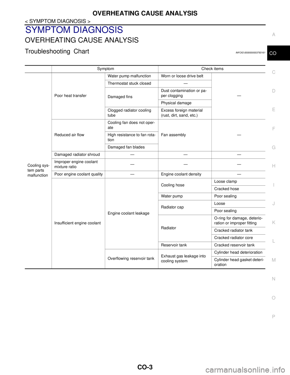
Troubleshooting ChartINFOID:0000000003793161
Symptom Check items
Cooling sys-
tem parts
malfunctionPoor heat transferWater pump malfunction Worn or loose drive belt
— Thermostat stuck closed —
Damaged finsDust contamination or pa-
per clogging
Physical damage
Clogged radiator cooling
tubeExcess foreign material
(rust, dirt, sand, etc.)
Reduced air flowCooling fan does not oper-
ate
Fan assembly — High resistance to fan rota-
tion
Damaged fan blades
Damaged radiator shroud — — —
Improper engine coolant
mixture ratio———
Poor engine coolant quality — Engine coolant density —
Insufficient engine coolantEngine coolant leakageCooling hoseLoose clamp
Cracked hose
Water pump Poor sealing
Radiator capLoose
Poor sealing
RadiatorO-ring for damage, deterio-
ration or improper fitting
Cracked radiator tank
Cracked radiator core
Reservoir tank Cracked reservoir tank
Overflowing reservoir tankExhaust gas leakage into
cooling systemCylinder head deterioration
Cylinder head gasket deteri-
oration
Page 1131 of 5121
CO-8
< ON-VEHICLE MAINTENANCE >
ENGINE COOLANT
ON-VEHICLE MAINTENANCE
ENGINE COOLANT
InspectionINFOID:0000000003793166
LEVEL
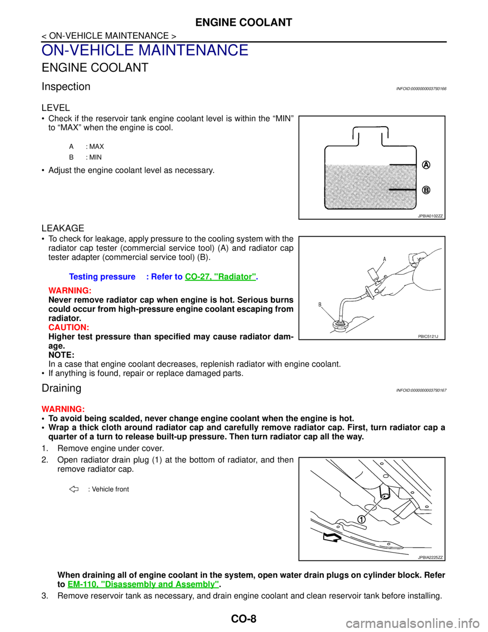
Check if the reservoir tank engine coolant level is within the “MIN”
to “MAX” when the engine is cool.
Adjust the engine coolant level as necessary.
LEAKAGE
To check for leakage, apply pressure to the cooling system with the
radiator cap tester (commercial service tool) (A) and radiator cap
tester adapter (commercial service tool) (B).
WARNING:
Never remove radiator cap when engine is hot. Serious burns
could occur from high-pressure engine coolant escaping from
radiator.
CAUTION:
Higher test pressure than specified may cause radiator dam-
age.
NOTE:
In a case that engine coolant decreases, replenish radiator with engine coolant.
If anything is found, repair or replace damaged parts.
DrainingINFOID:0000000003793167
WARNING:
To avoid being scalded, never change engine coolant when the engine is hot.
Wrap a thick cloth around radiator cap and carefully remove radiator cap. First, turn radiator cap a
quarter of a turn to release built-up pressure. Then turn radiator cap all the way.
1. Remove engine under cover.
2. Open radiator drain plug (1) at the bottom of radiator, and then
remove radiator cap.
When draining all of engine coolant in the system, open water drain plugs on cylinder block. Refer
to EM-110, "
Disassembly and Assembly".
3. Remove reservoir tank as necessary, and drain engine coolant and clean reservoir tank before installing.
A: MAX
B: MIN
JPBIA0102ZZ
Testing pressure : Refer to CO-27, "Radiator".
PBIC5121J
: Vehicle front
JPBIA2225ZZ
Page 1132 of 5121
ENGINE COOLANT
CO-9
< ON-VEHICLE MAINTENANCE >
C
D
E
F
G
H
I
J
K
L
MA
CO
N
P O
4. Check drained engine coolant for contaminants such as rust, corrosion or discoloration.
If contaminated, flush the engine cooling system. Refer to CO-10, "
Flushing".
RefillingINFOID:0000000003793168
1. Install reservoir tank if removed, and radiator drain plug.
CAUTION:
Be sure to clean drain plug and install with new O-ring.
If water drain plugs on cylinder block are removed, close and tighten them. Refer to EM-110, "
Dis-
assembly and Assembly".
2. Check that each hose clamp has been firmly tightened.
3. Remove air duct assembly and air cleaner cases (upper and lower) assembly. Refer to EM-26, "
Exploded
View".
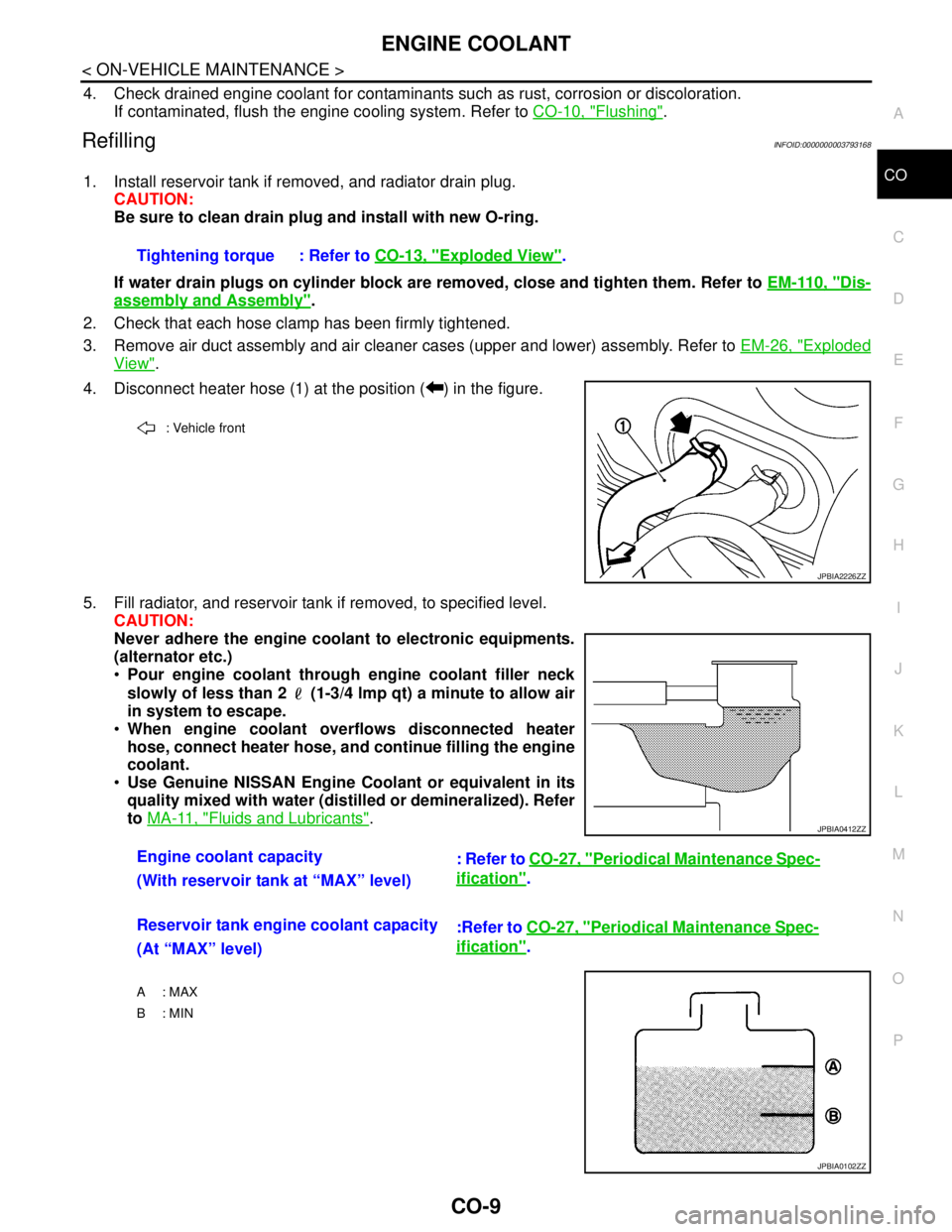
4. Disconnect heater hose (1) at the position ( ) in the figure.
5. Fill radiator, and reservoir tank if removed, to specified level.
CAUTION:
Never adhere the engine coolant to electronic equipments.
(alternator etc.)
Pour engine coolant through engine coolant filler neck
slowly of less than 2 (1-3/4 lmp qt) a minute to allow air
in system to escape.
When engine coolant overflows disconnected heater
hose, connect heater hose, and continue filling the engine
coolant.
Use Genuine NISSAN Engine Coolant or equivalent in its
quality mixed with water (distilled or demineralized). Refer
to MA-11, "
Fluids and Lubricants". Tightening torque : Refer to CO-13, "
Exploded View".
: Vehicle front
JPBIA2226ZZ
Engine coolant capacity
: Refer to CO-27, "Periodical Maintenance Spec-
ification".
(With reservoir tank at “MAX” level)
Reservoir tank engine coolant capacity
:Refer to CO-27, "
Periodical Maintenance Spec-
ification".
(At “MAX” level)
A : MAX
B: MIN
JPBIA0412ZZ
JPBIA0102ZZ
Page 1133 of 5121
CO-10
< ON-VEHICLE MAINTENANCE >
ENGINE COOLANT
6. Install air duct assembly and air cleaner cases (upper and lower) assembly. Refer to EM-26, "Exploded
View".
7. Install radiator cap.
8. Warm up engine until opening thermostat. Standard for warming-up time is approximately 10 minutes at
3,000 rpm.
Check thermostat opening condition by touching radiator hose (lower) to see a flow of warm water.
CAUTION:
Watch water temperature gauge so as not to overheat engine.
9. Stop the engine and cool down to less than approximately 50°C (122°F).
Cool down using fan to reduce the time.
If necessary, refill radiator up to filler neck with engine coolant.
CAUTION:
Never adhere the engine coolant to electronic equipments. (alternator etc.)
10. Refill reservoir tank to “MAX” level line with engine coolant.
11. Repeat steps 7 through 10 two or more times with radiator cap installed until engine coolant level no
longer drops.
12. Check cooling system for leakage with engine running.
13. Warm up the engine, and check for sound of engine coolant flow while running engine from idle up to
3,000 rpm with heater temperature controller set at several position between “COOL” and “WARM”.
Sound may be noticeable at heater unit.
14. Repeat step 13 three times.
15. If sound is heard, bleed air from cooling system by repeating step 5, and steps from 7 to 14 until engine
coolant level no longer drops.
FlushingINFOID:0000000003793169
1. Install reservoir tank if removed, and radiator drain plug.
CAUTION:
Be sure to clean drain plug and install with new O-ring.
If water drain plugs on cylinder block are removed, close and tighten them. Refer to EM-110, "
Dis-
assembly and Assembly".
2. Remove air duct assembly and air cleaner cases (upper and lower) assembly. Refer to EM-26, "
Exploded
View".
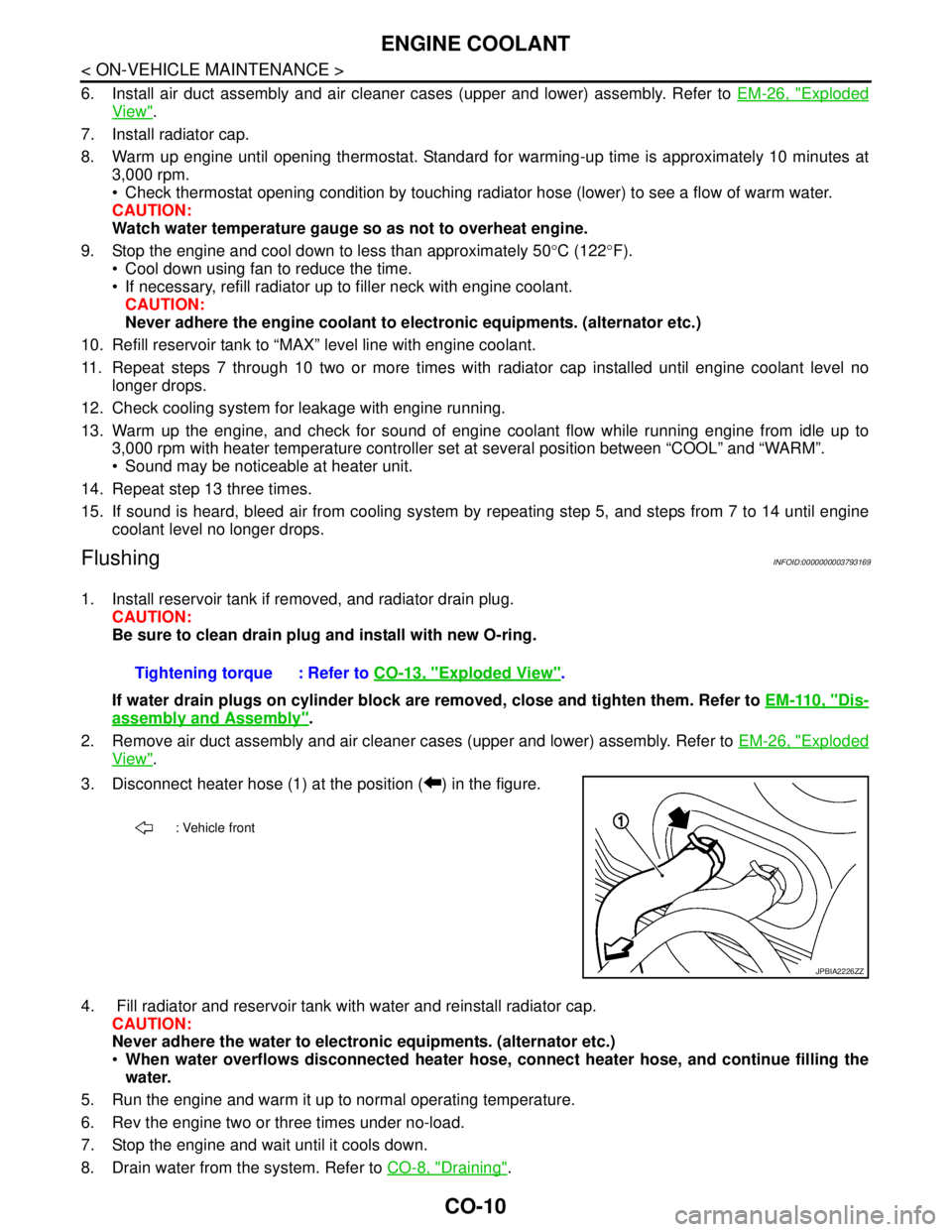
3. Disconnect heater hose (1) at the position ( ) in the figure.
4. Fill radiator and reservoir tank with water and reinstall radiator cap.
CAUTION:
Never adhere the water to electronic equipments. (alternator etc.)
When water overflows disconnected heater hose, connect heater hose, and continue filling the
water.
5. Run the engine and warm it up to normal operating temperature.
6. Rev the engine two or three times under no-load.
7. Stop the engine and wait until it cools down.
8. Drain water from the system. Refer to CO-8, "
Draining". Tightening torque : Refer to CO-13, "
Exploded View".
: Vehicle front
JPBIA2226ZZ
Page 1137 of 5121
CO-14
< ON-VEHICLE REPAIR >
RADIATOR
WARNING:
Never remove radiator cap when engine is hot. Serious burns could occur from high-pressure engine
coolant escaping from radiator. Wrap a thick cloth around the cap. Slowly turn it a quarter of a turn to
release built-up pressure. Carefully remove radiator cap by turning it all the way.
1. Remove the following parts:
Engine under cover.
Air duct (inlet): Refer to EM-26, "
Exploded View".
Horn: Refer to HRN-6, "
Exploded View".
Hood lock: Refer to DLK-220, "
Exploded View".
2. Drain engine coolant from radiator. Refer to CO-8, "
Draining".
CAUTION:
Perform this step when the engine is cold.
Never spill engine coolant on drive belt.
3. Disconnect reservoir tank hose from radiator pipe (upper).
4. Disconnect CVT fluid cooler hoses from radiator.
Install blind plug to avoid leakage of CVT fluid.
5. Disconnect Low-pressure flexible hose from lower pressure pipe, and then move it to aside. Refer to HA-
38, "Exploded View".
6. Remove radiator cap adapter and radiator hoses (upper) and radiator pipe (upper) assembly.
CAUTION:
Be careful not to allow engine coolant to contact drive belt.
7. Disconnect radiator hose (lower) from radiator.
8. Remove condenser. Refer to HA-46, "
Exploded View".
CAUTION:
Be careful not to damage condenser core.
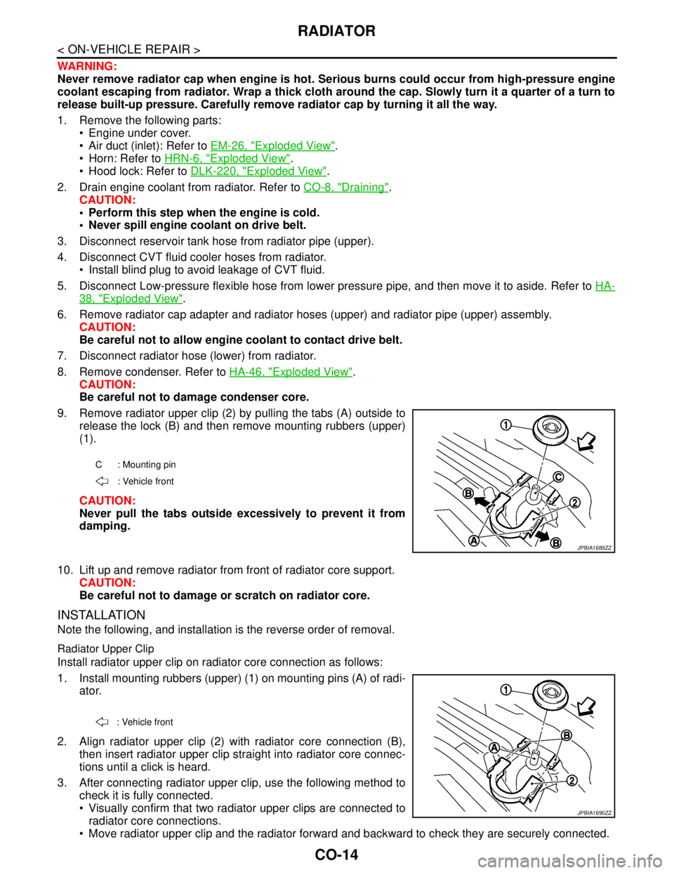
9. Remove radiator upper clip (2) by pulling the tabs (A) outside to
release the lock (B) and then remove mounting rubbers (upper)
(1).
CAUTION:
Never pull the tabs outside excessively to prevent it from
damping.
10. Lift up and remove radiator from front of radiator core support.
CAUTION:
Be careful not to damage or scratch on radiator core.
INSTALLATION
Note the following, and installation is the reverse order of removal.
Radiator Upper Clip
Install radiator upper clip on radiator core connection as follows:
1. Install mounting rubbers (upper) (1) on mounting pins (A) of radi-
ator.
2. Align radiator upper clip (2) with radiator core connection (B),
then insert radiator upper clip straight into radiator core connec-
tions until a click is heard.
3. After connecting radiator upper clip, use the following method to
check it is fully connected.
Visually confirm that two radiator upper clips are connected to
radiator core connections.
Move radiator upper clip and the radiator forward and backward to check they are securely connected.
C : Mounting pin
: Vehicle front
JPBIA1689ZZ
: Vehicle front
JPBIA1690ZZ
Page 1141 of 5121
CO-18
< ON-VEHICLE REPAIR >
WATER PUMP
WATER PUMP
Exploded ViewINFOID:0000000003793179
Removal and InstallationINFOID:0000000003793180
CAUTION:
When removing water pump assembly, be careful not to get engine coolant on drive belt.
Water pump cannot be disassembled and should be replaced as a unit.
After installing water pump, connect hose and clamp securely, then check for leakage using the radi-
ator cap tester (commercial service tool) and the radiator cap tester adapter (commercial service
tool).
REMOVAL
1. Remove the following parts.
Air duct (inlet): Refer to EM-26, "
Exploded View".
Engine cover: Refer to EM-24, "
Exploded View".
Engine under cover
Front road wheel and tire
Splash guard (RH): Refer to EXT-22, "
FENDER PROTECTOR : Exploded View".
2. Drain engine coolant from radiator. Refer to CO-8, "
Draining".
CAUTION:
Perform this step when the engine is cold.
Never spill engine coolant on drive belt.
3. Remove drive belt. Refer to EM-12, "
Removal and Installation".
4. Remove idler pulleys. Refer to EM-25, "
Exploded View".
5. Remove reservoir tank of radiator. Refer to CO-13, "
Exploded View".
6. Remove reservoir tank of power steering oil pump with piping connected, and move it to aside. Refer to
ST-34, "
Exploded View".
7. Support oil pan (lower) bottom with transmission jack.
8. Remove engine mounting insulator (RH), engine mounting bracket (RH) and upper torque rod. Refer to
EM-67, "
Exploded View".
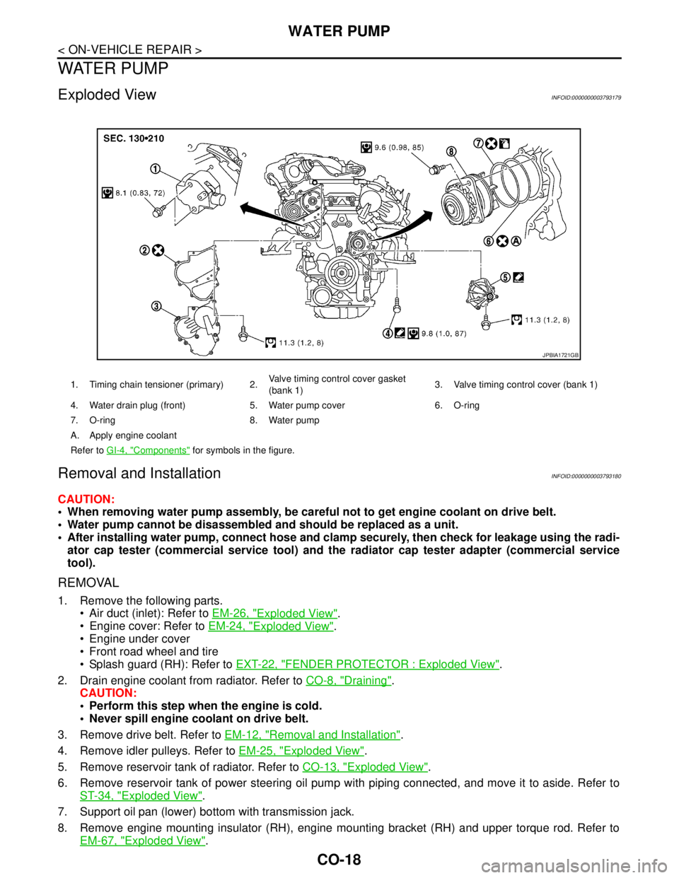
1. Timing chain tensioner (primary) 2.Valve timing control cover gasket
(bank 1)3. Valve timing control cover (bank 1)
4. Water drain plug (front) 5. Water pump cover 6. O-ring
7. O-ring 8. Water pump
A. Apply engine coolant
Refer to GI-4, "
Components" for symbols in the figure.
JPBIA1721GB
Page 1146 of 5121
WATER INLET AND THERMOSTAT ASSEMBLY
CO-23
< ON-VEHICLE REPAIR >
C
D
E
F
G
H
I
J
K
L
MA
CO
N
P O
WATER INLET AND THERMOSTAT ASSEMBLY
Exploded ViewINFOID:0000000003793182
Removal and InstallationINFOID:0000000003793183
REMOVAL
1. Drain engine coolant from radiator drain plug at the bottom of radiator, and from water drain plug at the
front of cylinder block. Refer to CO-8, "
Draining" and EM-107, "Exploded View".
CAUTION:
Perform this step when the engine is cold.
Never spill engine coolant on drive belt.
2. Remove reservoir tank of radiator, and move it aside. Refer to CO-13, "
Exploded View".
3. Remove intake valve timing control solenoid valve (bank 2). Refer toEM-52, "
Exploded View".
4. Disconnect radiator hose (lower) from water inlet and thermostat assembly.
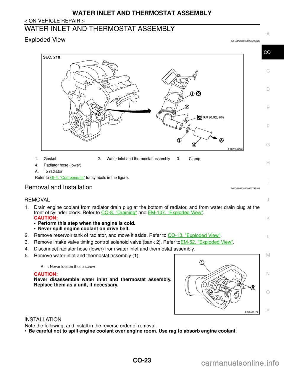
5. Remove water inlet and thermostat assembly (1).
CAUTION:
Never disassemble water inlet and thermostat assembly.
Replace them as a unit, if necessary.
INSTALLATION
Note the following, and install in the reverse order of removal.
Be careful not to spill engine coolant over engine room. Use rag to absorb engine coolant.
1. Gasket 2. Water inlet and thermostat assembly 3. Clamp
4. Radiator hose (lower)
A. To radiator
Refer to GI-4, "
Components" for symbols in the figure.
JPBIA1688GB
A : Never loosen these screw
JPBIA0261ZZ
Page 1150 of 5121
SERVICE DATA AND SPECIFICATIONS (SDS)
CO-27
< SERVICE DATA AND SPECIFICATIONS (SDS)
C
D
E
F
G
H
I
J
K
L
MA
CO
N
P O
SERVICE DATA AND SPECIFICATIONS (SDS)
SERVICE DATA AND SPECIFICATIONS (SDS)
Periodical Maintenance SpecificationINFOID:0000000003793188
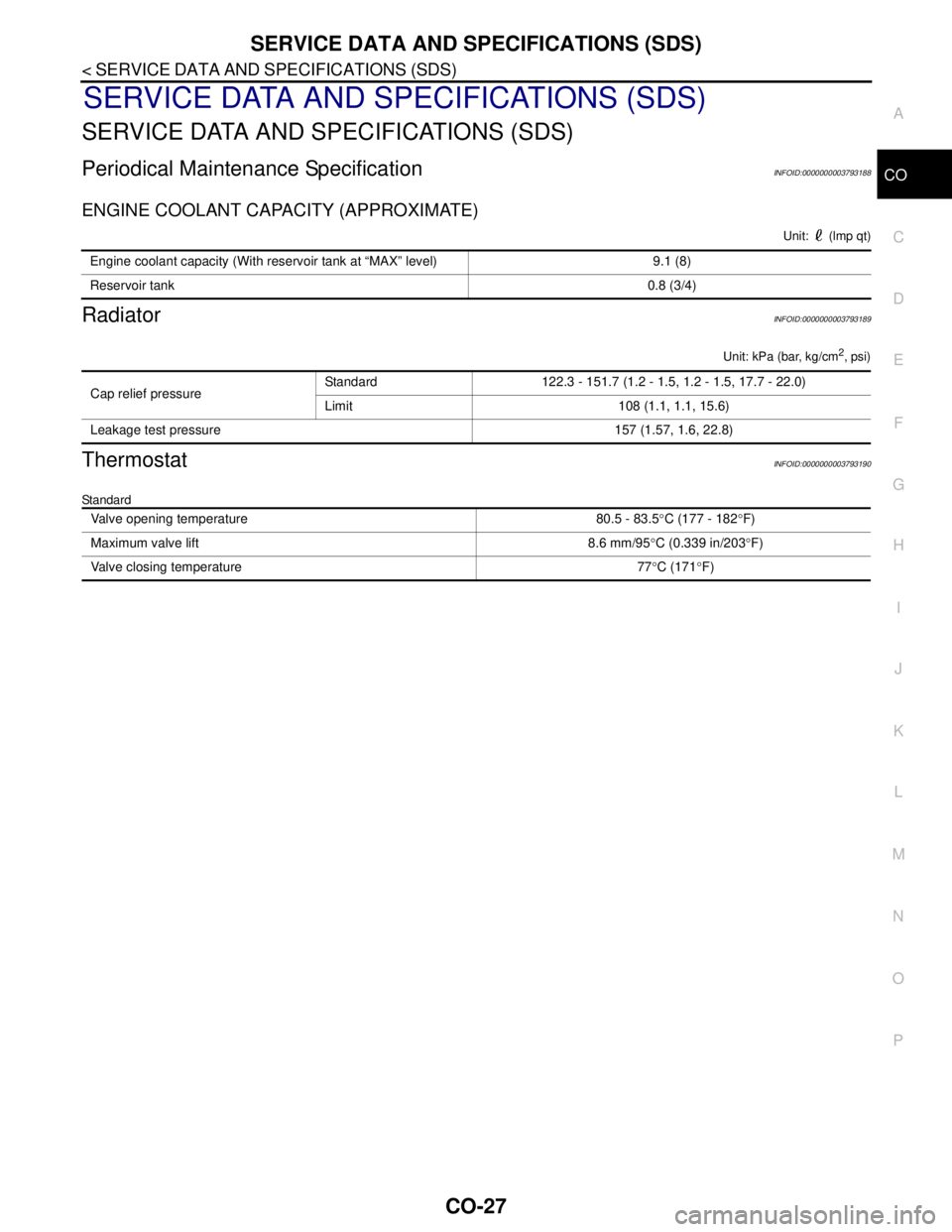
ENGINE COOLANT CAPACITY (APPROXIMATE)
Unit: (lmp qt)
RadiatorINFOID:0000000003793189
Unit: kPa (bar, kg/cm2, psi)
ThermostatINFOID:0000000003793190
Standard
Engine coolant capacity (With reservoir tank at “MAX” level) 9.1 (8)
Reservoir tank0.8 (3/4)
Cap relief pressureStandard 122.3 - 151.7 (1.2 - 1.5, 1.2 - 1.5, 17.7 - 22.0)
Limit 108 (1.1, 1.1, 15.6)
Leakage test pressure 157 (1.57, 1.6, 22.8)
Valve opening temperature 80.5 - 83.5°C (177 - 182°F)
Maximum valve lift 8.6 mm/95°C (0.339 in/203°F)
Valve closing temperature 77°C (171°F)
Page 1413 of 5121
![NISSAN TEANA 2008 Service Manual RADIATOR CORE SUPPORT
DLK-197
< ON-VEHICLE REPAIR >[WITH INTELLIGENT KEY SYSTEM]
C
D
E
F
G
H
I
J
L
MA
B
DLK
N
O
P
13. Disconnect connector of refrigerant pressure sensor. Refer to HA-50, "Exploded Vie NISSAN TEANA 2008 Service Manual RADIATOR CORE SUPPORT
DLK-197
< ON-VEHICLE REPAIR >[WITH INTELLIGENT KEY SYSTEM]
C
D
E
F
G
H
I
J
L
MA
B
DLK
N
O
P
13. Disconnect connector of refrigerant pressure sensor. Refer to HA-50, "Exploded Vie](/img/5/57391/w960_57391-1412.png)
RADIATOR CORE SUPPORT
DLK-197
< ON-VEHICLE REPAIR >[WITH INTELLIGENT KEY SYSTEM]
C
D
E
F
G
H
I
J
L
MA
B
DLK
N
O
P
13. Disconnect connector of refrigerant pressure sensor. Refer to HA-50, "Exploded View".
14. Remove mounting bolt, and then remove engine coolant reservoir tank. Refer to CO-13, "
Exploded View".
15. Remove mounting bolts, and then disconnect condenser pipe assembly. Refer to HA-48, "
Exploded
View".
16. Remove condenser. Refer to HA-46, "
Removal and Installation".
17. Remove mounting nut of radiator upper hose from radiator core support, and then remove radiator upper
hose and hood switch bracket. Refer to CO-25, "
Exploded View".
18. Disconnect radiator upper hose from radiator pipe (upper). Refer to CO-25, "
Exploded View".
19. Disconnect radiator lower hose (3). Refer to CO-25, "
Exploded View".
20. Disconnect CVT fluid cooler hose on radiator side. Refer to TM-165, "
Exploded View" (CVT: RE0F09B) or
TM-329, "
Exploded View" (CVT: RE0F10A).
21. Remove power steering oil cooler pipe from radiator core sup-
port at point shown by arrows in the figure.
22. Disconnect connectors of the following parts.
Cooling fan (RH/LH). Refer to CO-16, "
Exploded View".
Crash zone sensor. Refer to SR-18, "
Removal and Installation".
23. Remove radiator upper clip. Refer to CO-13, "
Exploded View".
24. Remove all harness clips from radiator core support.
CAUTION:
Never damage radiator.
25. Support hood assembly with a proper material to prevent it from falling.
WARNING:
Bodily injury may occur if no supporting rod is holding the hood open when removing the hood
stay.
26. Remove hood support rod. Refer to DLK-195, "
HOOD SUPPORT ROD : Removal and Installation".
27. Remove mounting bolts, and then remove radiator core support.
CAUTION:
Operate with two workers, because of its heavy weight.
Never damage power steering oil cooler pipe.
28. Remove the following parts after removing radiator core support.
Radiator lower hose, radiator upper hose, radiator pipe. Refer to CO-25, "
Exploded View".
Radiator. Refer to CO-13, "
Exploded View".
Cooling fan (RH/LH). Refer to CO-16, "
Exploded View".
Crash zone sensor. Refer to SR-18, "
Exploded View".
Power steering oil cooler pipe clip. Refer to ST-34, "
Exploded View".
INSTALLATION
Install in the reverse order of removal.
JMKIA2395ZZ
: harness clip
JMKIA2396ZZ
Page 1712 of 5121
![NISSAN TEANA 2008 Service Manual P1217 ENGINE OVER TEMPERATURE
EC-251
< COMPONENT DIAGNOSIS >[VQ25DE, VQ35DE]
C
D
E
F
G
H
I
J
K
L
MA
EC
N
P O
Check the coolant level in the reservoir tank and radiator.
Allow engine to cool before che NISSAN TEANA 2008 Service Manual P1217 ENGINE OVER TEMPERATURE
EC-251
< COMPONENT DIAGNOSIS >[VQ25DE, VQ35DE]
C
D
E
F
G
H
I
J
K
L
MA
EC
N
P O
Check the coolant level in the reservoir tank and radiator.
Allow engine to cool before che](/img/5/57391/w960_57391-1711.png)
P1217 ENGINE OVER TEMPERATURE
EC-251
< COMPONENT DIAGNOSIS >[VQ25DE, VQ35DE]
C
D
E
F
G
H
I
J
K
L
MA
EC
N
P O
Check the coolant level in the reservoir tank and radiator.
Allow engine to cool before checking coolant level.
Is the coolant level in the reservoir tank and/or radiator below the
proper range?
YES >> Go to EC-251, "Diagnosis Procedure".
NO >> GO TO 2.
2.PERFORM COMPONENT FUNCTION CHECK-II
Confirm whether customer filled the coolant or not.
Did customer fill the coolant?
YES >> Go to EC-251, "Diagnosis Procedure".
NO >> GO TO 3.
3.PERFORM COMPONENT FUNCTION CHECK-III
With CONSULT-III
1. Turn ignition switch ON.
2. Perform “COOLING FAN” in “ACTIVE TEST” mode with CONSULT-III.
3. Check that cooling fan motors-1 and -2 operate at each speed (LOW/MID/HI).
Without CONSULT-III
Perform IPDM E/R auto active test and check cooling fan motors operation, refer to PCS-11, "
Diagnosis
Description".
Is the inspection result normal?
YES >> INSPECTION END
NO >> Go to EC-251, "
Diagnosis Procedure".
Diagnosis ProcedureINFOID:0000000003856720
1.CHECK COOLING FAN OPERATION
With CONSULT-III
1. Turn ignition switch ON.
2. Perform “COOLING FAN” in “ACTIVE TEST” mode with CONSULT-III.
3. Check that cooling fans-1 and -2 operate at each speed (LOW/MID/HI).
Without CONSULT-III
1. Perform IPDM E/R auto active test and check cooling fan motors operation, refer to PCS-11, "
Diagnosis
Description".
2. Check that cooling fans-1 and -2 operate at each speed (Low/Middle/High).
Is the inspection result normal?
YES >> GO TO 2.
NO >> Go to EC-324, "
Diagnosis Procedure".
2.CHECK COOLING SYSTEM FOR LEAK-I
Check cooling system for leak. Refer to CO-8, "
Inspection".
Is leakage detected?
YES >> GO TO 3.
NO >> GO TO 4.
3.CHECK COOLING SYSTEM FOR LEAK-II
Check the following for leak.
Hose
Radiator
Water pump
SEF621W