wheel bolts NISSAN TEANA 2008 Owner's Manual
[x] Cancel search | Manufacturer: NISSAN, Model Year: 2008, Model line: TEANA, Model: NISSAN TEANA 2008Pages: 5121, PDF Size: 69.03 MB
Page 3846 of 5121
RSU-14
< ON-VEHICLE REPAIR >
FRONT LOWER LINK
FRONT LOWER LINK
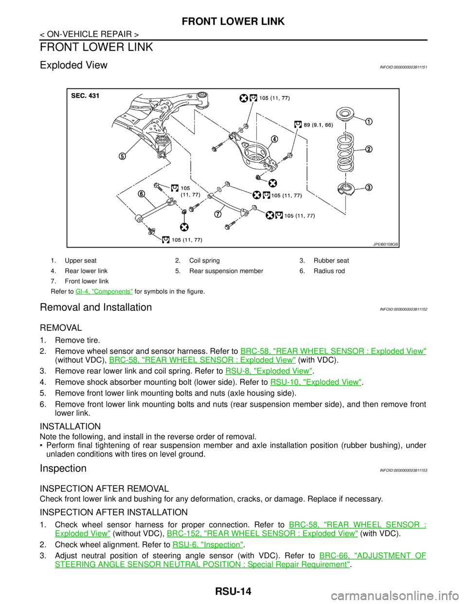
Exploded ViewINFOID:0000000003811151
Removal and InstallationINFOID:0000000003811152
REMOVAL
1. Remove tire.
2. Remove wheel sensor and sensor harness. Refer to BRC-58, "
REAR WHEEL SENSOR : Exploded View"
(without VDC), BRC-58, "REAR WHEEL SENSOR : Exploded View" (with VDC).
3. Remove rear lower link and coil spring. Refer to RSU-8, "
Exploded View".
4. Remove shock absorber mounting bolt (lower side). Refer to RSU-10, "
Exploded View".
5. Remove front lower link mounting bolts and nuts (axle housing side).
6. Remove front lower link mounting bolts and nuts (rear suspension member side), and then remove front
lower link.
INSTALLATION
Note the following, and install in the reverse order of removal.
Perform final tightening of rear suspension member and axle installation position (rubber bushing), under
unladen conditions with tires on level ground.
InspectionINFOID:0000000003811153
INSPECTION AFTER REMOVAL
Check front lower link and bushing for any deformation, cracks, or damage. Replace if necessary.
INSPECTION AFTER INSTALLATION
1. Check wheel sensor harness for proper connection. Refer to BRC-58, "REAR WHEEL SENSOR :
Exploded View" (without VDC), BRC-152, "REAR WHEEL SENSOR : Exploded View" (with VDC).
2. Check wheel alignment. Refer to RSU-6, "
Inspection".
3. Adjust neutral position of steering angle sensor (with VDC). Refer to BRC-66, "
ADJUSTMENT OF
STEERING ANGLE SENSOR NEUTRAL POSITION : Special Repair Requirement".
1. Upper seat 2. Coil spring 3. Rubber seat
4. Rear lower link 5. Rear suspension member 6. Radius rod
7. Front lower link
Refer to GI-4, "
Components" for symbols in the figure.
JPEIB0108GB
Page 4222 of 5121

SR-8
< ON-VEHICLE REPAIR >
DRIVER AIR BAG MODULE
Tighten the TORX bolts after completely adjusting the centers of fixing holes on the driver air bag
module side and the steering wheel side. If the holes are misaligned, the bolt threads are damaged
and the module is not installed securely.
In the case that a malfunction is detected by the air bag warning lamp, after repair or replacement of
the malfunctioning parts, reset the memory by self-diagnosis or by CONSULT-III.
After the work is completed, check that no system malfunction is detected by air bag warning lamp.
Refer to SRC-10, "
Diagnosis Description".
Page 4242 of 5121
SR-28
< ON-VEHICLE REPAIR >
DISPOSAL OF AIR BAG MODULE AND SEAT BELT PRE-TENSIONER
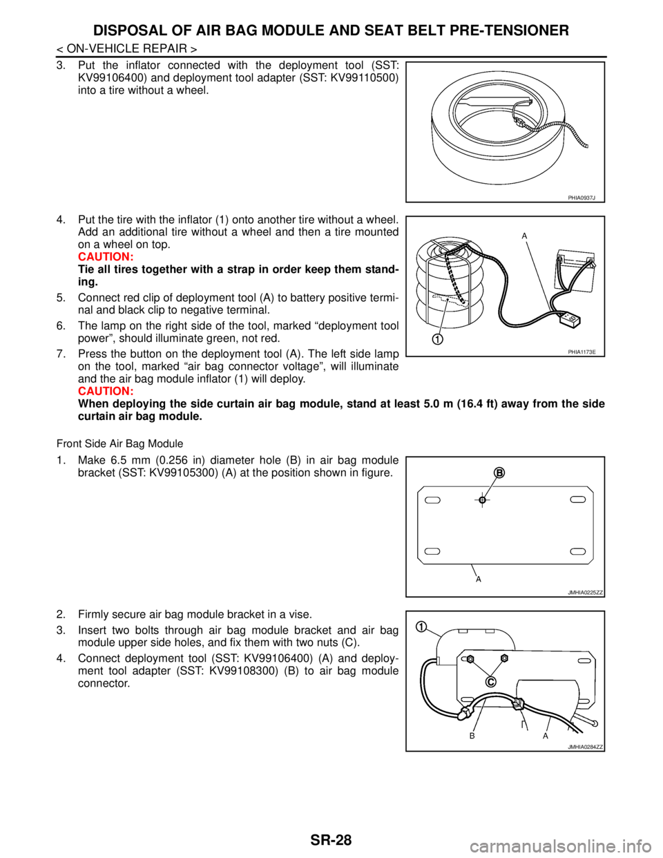
3. Put the inflator connected with the deployment tool (SST:
KV99106400) and deployment tool adapter (SST: KV99110500)
into a tire without a wheel.
4. Put the tire with the inflator (1) onto another tire without a wheel.
Add an additional tire without a wheel and then a tire mounted
on a wheel on top.
CAUTION:
Tie all tires together with a strap in order keep them stand-
ing.
5. Connect red clip of deployment tool (A) to battery positive termi-
nal and black clip to negative terminal.
6. The lamp on the right side of the tool, marked “deployment tool
power”, should illuminate green, not red.
7. Press the button on the deployment tool (A). The left side lamp
on the tool, marked “air bag connector voltage”, will illuminate
and the air bag module inflator (1) will deploy.
CAUTION:
When deploying the side curtain air bag module, stand at least 5.0 m (16.4 ft) away from the side
curtain air bag module.
Front Side Air Bag Module
1. Make 6.5 mm (0.256 in) diameter hole (B) in air bag module
bracket (SST: KV99105300) (A) at the position shown in figure.
2. Firmly secure air bag module bracket in a vise.
3. Insert two bolts through air bag module bracket and air bag
module upper side holes, and fix them with two nuts (C).
4. Connect deployment tool (SST: KV99106400) (A) and deploy-
ment tool adapter (SST: KV99108300) (B) to air bag module
connector.
PHIA0937J
PHIA1173E
JMHIA0225ZZ
JMHIA0284ZZ
Page 4275 of 5121
SRC-32
< COMPONENT DIAGNOSIS >
B1049 DRIVER AIRBAG MODULE
B1049 DRIVER AIRBAG MODULE
DescriptionINFOID:0000000003813957
For driver air bag module, crash is judged by main “G” sensor output signal and safing algorithm in front direc-
tion.
OPERATION
In case of frontal collision whose acceleration exceeds the specified level, the ignition materials are ignited by
electric ignition system. The system burns the gas generating materials resulting in a chemical reaction. This
generates hot gases that flow into the air bag through a filter and expand the bag.
STRUCTURE
Driver air bag module mainly consists of air bag and inflator which inflates air bag.
INSTALLATION
Driver air bag module is installed on the center of steering wheel with fixed bolts.
DTC LogicINFOID:0000000003813958
DTC CONFIRMATION PROCEDURE
1.CHECK SELF-DIAG RESULT
With CONSULT-III
1. Turn ignition switch ON.
2. Perform “AIR BAG” Self Diagnostic Result.
Without CONSULT-III
1. Turn ignition switch ON.
2. Check the air bag warning lamp status. Refer to SRC-10, "
Air Bag Warning Lamp Diagnosis".
NOTE:
SRS does not enter Diagnosis mode if no malfunction is detected in User mode.
Is malfunctioning part detected?
YES >> Refer to SRC-32, "Diagnosis Procedure".
NO >> INSPECTION END
Diagnosis ProcedureINFOID:0000000003813959
WARNING:
With CONSULT-III
Before servicing, turn ignition switch OFF, disconnect battery negative terminal and wait at least 3
minutes. (To discharge backup capacitor.)
Never use unspecified tester or other measuring device.
1.CHECK HARNESS CONNECTOR
Check the harness connector.
Is the inspection result normal?
YES >> GO TO 2.
NO >> Replace harness connector.
2.CHECK WIRING HARNESS
Check the wiring harness externals.
Is the inspection result normal?
DTC No. Trouble diagnosis name DTC detecting condition Possible cause
B1049 DRIVER AIRBAG MOD-
ULE
[OPEN]Driver air bag module circuit is open
(including the spiral cable) Disconnection of wiring harness and
open
Malfunction in driver air bag module
Malfunction in spiral cable
Malfunction in air bag diagnosis sen-
sor unit
Page 4277 of 5121
SRC-34
< COMPONENT DIAGNOSIS >
B1050 DRIVER AIRBAG MODULE
B1050 DRIVER AIRBAG MODULE
DescriptionINFOID:0000000003813960
For driver air bag module, crash is judged by main “G” sensor output signal and safing algorithm in front direc-
tion.
OPERATION
In case of frontal collision whose acceleration exceeds the specified level, the ignition materials are ignited by
electric ignition system. The system burns the gas generating materials resulting in a chemical reaction. This
generates hot gases that flow into the air bag through a filter and expand the bag.
STRUCTURE
Driver air bag module mainly consists of air bag and inflator which inflates air bag.
INSTALLATION
Driver air bag module is installed on the center of steering wheel with fixed bolts.
DTC LogicINFOID:0000000003813961
DTC CONFIRMATION PROCEDURE
1.CHECK SELF-DIAG RESULT
With CONSULT-III
1. Turn ignition switch ON.
2. Perform “AIR BAG” Self Diagnostic Result.
Without CONSULT-III
1. Turn ignition switch ON.
2. Check the air bag warning lamp status. Refer to SRC-10, "
Air Bag Warning Lamp Diagnosis".
NOTE:
SRS does not enter Diagnosis mode if no malfunction is detected in User mode.
Is malfunctioning part detected?
YES >> Refer to SRC-34, "Diagnosis Procedure".
NO >> INSPECTION END
Diagnosis ProcedureINFOID:0000000003813962
WARNING:
Before servicing, turn ignition switch OFF, disconnect battery negative terminal and wait at least 3
minutes. (To discharge backup capacitor.)
Never use unspecified tester or other measuring device.
1.CHECK HARNESS CONNECTOR
Check the harness connector.
Is the inspection result normal?
YES >> GO TO 2.
NO >> Replace harness connector.
2.CHECK WIRING HARNESS
Check the wiring harness externals.
Is the inspection result normal?
YES >> GO TO 3.
DTC No. Trouble diagnosis name DTC detecting condition Possible cause
B1050 DRIVER AIRBAG MOD-
ULE
[VB-SHORT]Driver air bag module circuit is shorted
to some power supply circuit
(including the spiral cable) Disconnection of wiring harness and
short
Malfunction in driver air bag module
Malfunction in spiral cable
Malfunction in air bag diagnosis sen-
sor unit
Page 4279 of 5121
SRC-36
< COMPONENT DIAGNOSIS >
B1051 DRIVER AIRBAG MODULE
B1051 DRIVER AIRBAG MODULE
DescriptionINFOID:0000000003813963
For driver air bag module, crash is judged by main “G” sensor output signal and safing algorithm in front direc-
tion.
OPERATION
In case of frontal collision whose acceleration exceeds the specified level, the ignition materials are ignited by
electric ignition system. The system burns the gas generating materials resulting in a chemical reaction. This
generates hot gases that flow into the air bag through a filter and expand the bag.
STRUCTURE
Driver air bag module mainly consists of air bag and inflator which inflates air bag.
INSTALLATION
Driver air bag module is installed on the center of steering wheel with fixed bolts.
DTC LogicINFOID:0000000003813964
DTC CONFIRMATION PROCEDURE
1.CHECK SELF-DIAG RESULT
With CONSULT-III
1. Turn ignition switch ON.
2. Perform “AIR BAG” Self Diagnostic Result.
Without CONSULT-III
1. Turn ignition switch ON.
2. Check the air bag warning lamp status. Refer to SRC-10, "
Air Bag Warning Lamp Diagnosis".
NOTE:
SRS does not enter Diagnosis mode if no malfunction is detected in User mode.
Is malfunctioning part detected?
YES >> Refer to SRC-36, "Diagnosis Procedure".
NO >> INSPECTION END
Diagnosis ProcedureINFOID:0000000003813965
WARNING:
Before servicing, turn ignition switch OFF, disconnect battery negative terminal and wait at least 3
minutes. (To discharge backup capacitor.)
Never use unspecified tester or other measuring device.
1.CHECK HARNESS CONNECTOR
Check the harness connector.
Is the inspection result normal?
YES >> GO TO 2.
NO >> Replace harness connector.
2.CHECK WIRING HARNESS
Check the wiring harness externals.
Is the inspection result normal?
YES >> GO TO 3.
DTC No. Trouble diagnosis name DTC detecting condition Possible cause
B1051 DRIVER AIRBAG MOD-
ULE
[GND-SHORT]Driver air bag module circuit is shorted
to ground
(including the spiral cable) Disconnection of wiring harness and
short
Malfunction in driver air bag module
Malfunction in spiral cable
Malfunction in air bag diagnosis sen-
sor unit
Page 4281 of 5121
SRC-38
< COMPONENT DIAGNOSIS >
B1052 DRIVER AIRBAG MODULE
B1052 DRIVER AIRBAG MODULE
DescriptionINFOID:0000000003813966
For driver air bag module, crash is judged by main “G” sensor output signal and safing algorithm in front direc-
tion.
OPERATION
In case of frontal collision whose acceleration exceeds the specified level, the ignition materials are ignited by
electric ignition system. The system burns the gas generating materials resulting in a chemical reaction. This
generates hot gases that flow into the air bag through a filter and expand the bag.
STRUCTURE
Driver air bag module mainly consists of air bag and inflator which inflates air bag.
INSTALLATION
Driver air bag module is installed on the center of steering wheel with fixed bolts.
DTC LogicINFOID:0000000003813967
DTC CONFIRMATION PROCEDURE
1.CHECK SELF-DIAG RESULT
With CONSULT-III
1. Turn ignition switch ON.
2. Perform “AIR BAG” Self Diagnostic Result.
Without CONSULT-III
1. Turn ignition switch ON.
2. Check the air bag warning lamp status. Refer to SRC-10, "
Air Bag Warning Lamp Diagnosis".
NOTE:
SRS does not enter Diagnosis mode if no malfunction is detected in User mode.
Is malfunctioning part detected?
YES >> Refer to SRC-38, "Diagnosis Procedure".
NO >> INSPECTION END
Diagnosis ProcedureINFOID:0000000003813968
WARNING:
Before servicing, turn ignition switch OFF, disconnect battery negative terminal and wait at least 3
minutes. (To discharge backup capacitor.)
Never use unspecified tester or other measuring device.
1.CHECK HARNESS CONNECTOR
Check the harness connector.
Is the inspection result normal?
YES >> GO TO 2.
NO >> Replace harness connector.
2.CHECK WIRING HARNESS
Check the wiring harness externals.
Is the inspection result normal?
YES >> GO TO 3.
DTC No. Trouble diagnosis name DTC detecting condition Possible cause
B1052 DRIVER AIRBAG MOD-
ULE
[SHORT]Driver air bag module circuit are shorted
to each other
(including the spiral cable) Disconnection of wiring harness
and short
Malfunction in driver air bag module
Malfunction in spiral cable
Malfunction in air bag diagnosis sen-
sor unit
Page 4409 of 5121
STEERING GEAR AND LINKAGE
ST-19
< ON-VEHICLE REPAIR >
C
D
E
F
H
I
J
K
L
MA
B
ST
N
O
P
Removal and InstallationINFOID:0000000003806323
REMOVAL
1. Set the vehicle to the straight-ahead position.
2. Remove front tires.
3. Remove splash guards (RH and LH). Refer to EXT-22, "
FENDER PROTECTOR : Exploded View".
4. Remove engine under cover. Refer to EXT-28, "
Exploded View".
5. Remove heat insulator from front floor.
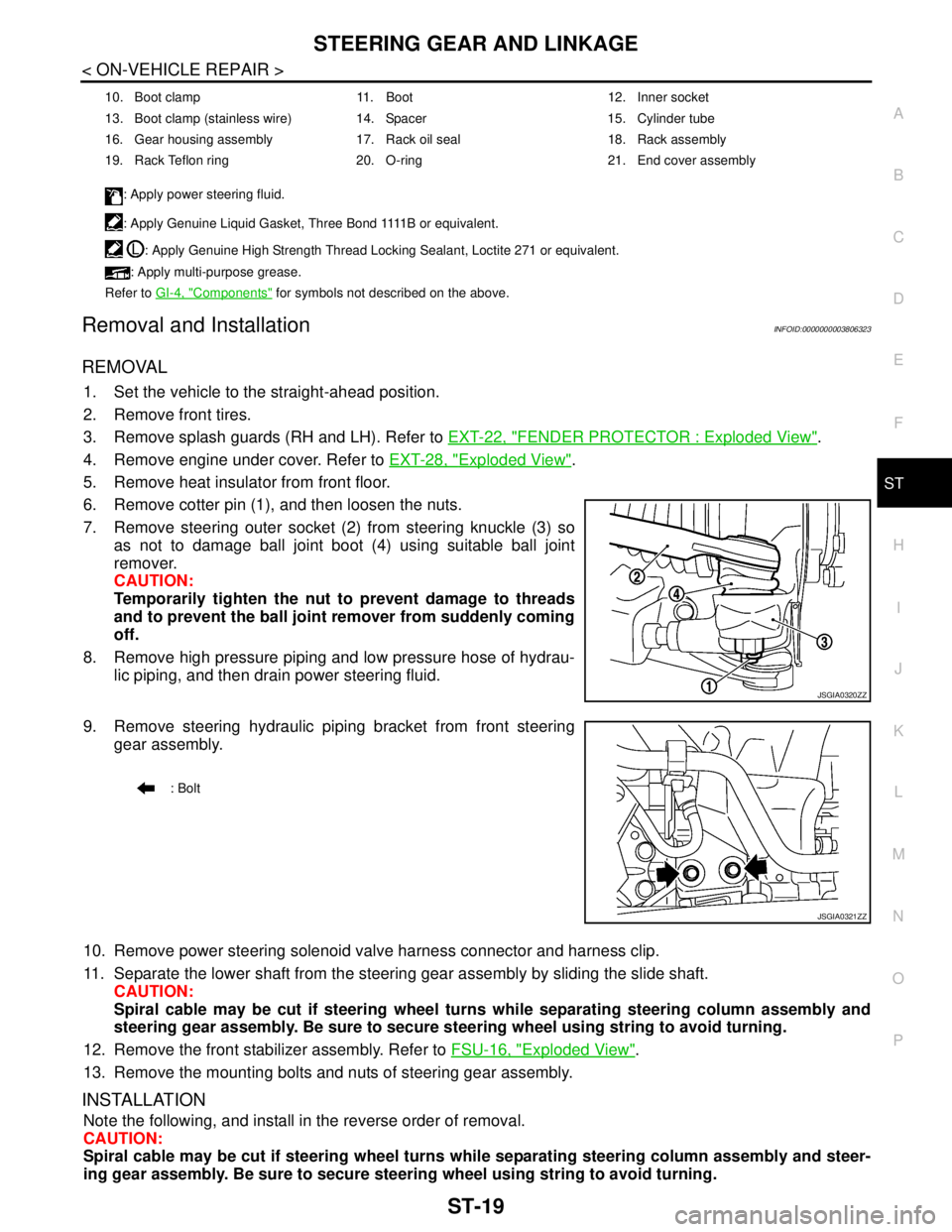
6. Remove cotter pin (1), and then loosen the nuts.
7. Remove steering outer socket (2) from steering knuckle (3) so
as not to damage ball joint boot (4) using suitable ball joint
remover.
CAUTION:
Temporarily tighten the nut to prevent damage to threads
and to prevent the ball joint remover from suddenly coming
off.
8. Remove high pressure piping and low pressure hose of hydrau-
lic piping, and then drain power steering fluid.
9. Remove steering hydraulic piping bracket from front steering
gear assembly.
10. Remove power steering solenoid valve harness connector and harness clip.
11. Separate the lower shaft from the steering gear assembly by sliding the slide shaft.
CAUTION:
Spiral cable may be cut if steering wheel turns while separating steering column assembly and
steering gear assembly. Be sure to secure steering wheel using string to avoid turning.
12. Remove the front stabilizer assembly. Refer to FSU-16, "
Exploded View".
13. Remove the mounting bolts and nuts of steering gear assembly.
INSTALLATION
Note the following, and install in the reverse order of removal.
CAUTION:
Spiral cable may be cut if steering wheel turns while separating steering column assembly and steer-
ing gear assembly. Be sure to secure steering wheel using string to avoid turning.
10. Boot clamp 11. Boot 12. Inner socket
13. Boot clamp (stainless wire) 14. Spacer 15. Cylinder tube
16. Gear housing assembly 17. Rack oil seal 18. Rack assembly
19. Rack Teflon ring 20. O-ring 21. End cover assembly
: Apply power steering fluid.
: A p p l y G e n u i n e L i q u i d G a s k e t , T h r e e B o n d 1111 B o r e q u i v a l e n t .
: Apply Genuine High Strength Thread Locking Sealant, Loctite 271 or equivalent.
: Apply multi-purpose grease.
Refer to GI-4, "
Components" for symbols not described on the above.
JSGIA0320ZZ
: Bolt
JSGIA0321ZZ
Page 4410 of 5121
ST-20
< ON-VEHICLE REPAIR >
STEERING GEAR AND LINKAGE
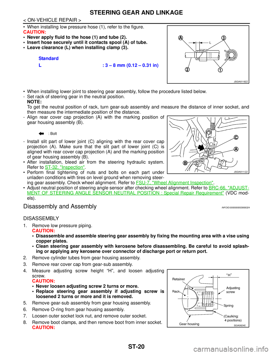
When installing low pressure hose (1), refer to the figure.
CAUTION:
Never apply fluid to the hose (1) and tube (2).
Insert hose securely until it contacts spool (A) of tube.
Leave clearance (L) when installing clamp (3).
When installing lower joint to steering gear assembly, follow the procedure listed below.
- Set rack of steering gear in the neutral position.
NOTE:
To get the neutral position of rack, turn gear-sub assembly and measure the distance of inner socket, and
then measure the intermediate position of the distance.
- Align rear cover cap projection (A) with the marking position of
gear housing assembly (B).
- Install slit part of lower joint (C) aligning with the rear cover cap
projection (A). Make sure that the slit part of lower joint (C) is
aligned with rear cover cap projection (A) and the marking position
of gear housing assembly (B).
After installation, bleed air from the steering hydraulic system.
Refer to ST-32, "
Inspection".
Perform final tightening of nuts and bolts on each part under
unladen conditions with tires on level ground when removing steer-
ing gear assembly. Check wheel alignment. Refer to FSU-7, "
Wheel Alignment Inspection".
Adjust neutral position of steering angle sensor after checking wheel alignment. Refer to BRC-66, "
ADJUST-
MENT OF STEERING ANGLE SENSOR NEUTRAL POSITION : Special Repair Requirement" (VDC mod-
els).
Disassembly and AssemblyINFOID:0000000003806324
DISASSEMBLY
1. Remove low pressure piping.
CAUTION:
Disassemble and assemble steering gear assembly by fixing the mounting area with a vise using
copper plates.
Clean steering gear assembly with kerosene before disassembling. Be careful to avoid splash-
ing or applying any kerosene over connector of discharge port or return port.
2. Remove cylinder tubes from gear housing assembly.
3. Remove rear cover cap from gear-sub assembly.
4. Measure adjusting screw height “H”, and loosen adjusting
screw.
CAUTION:
Never loosen adjusting screw 2 turns or more.
Replace steering gear assembly if adjusting screw is
loosened 2 turns or more and it is removed.
5. Remove gear-sub assembly from gear housing assembly.
6. Remove O-ring from gear housing assembly.
7. Loosen outer socket lock nut, and remove outer socket.
8. Remove boot clamps, and then remove boot from inner socket.
CAUTION:Standard
L : 3 – 8 mm (0.12 – 0.31 in)
JSGIA0118ZZ
: Bolt
J S G I A 0 111 Z Z
SGIA0624E