light NISSAN TEANA 2014 Service Manual
[x] Cancel search | Manufacturer: NISSAN, Model Year: 2014, Model line: TEANA, Model: NISSAN TEANA 2014Pages: 4801, PDF Size: 51.2 MB
Page 2036 of 4801
EM-38
< REMOVAL AND INSTALLATION >[QR25DE]
OIL PAN AND OIL STRAINER
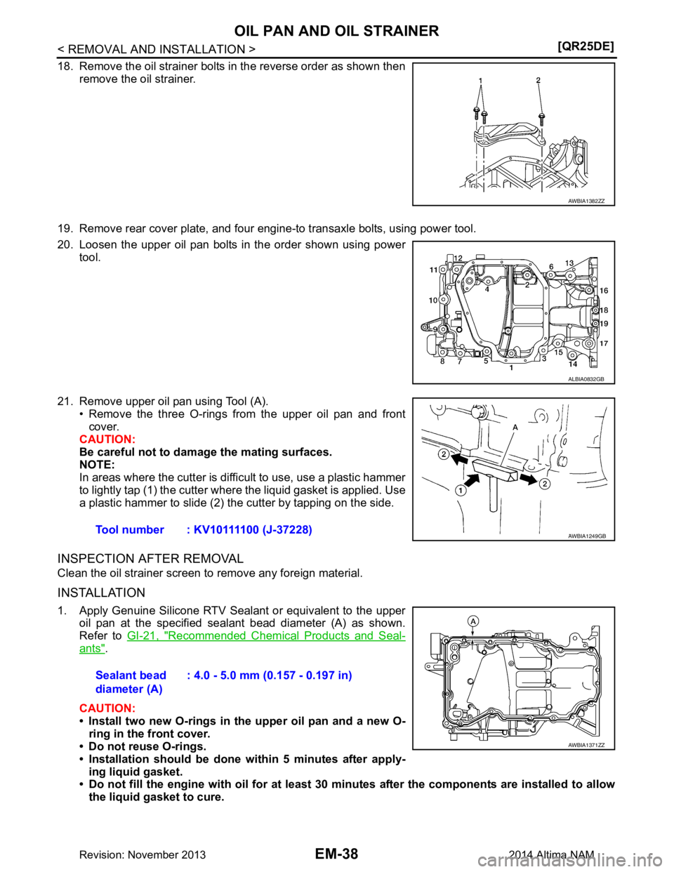
18. Remove the oil strainer bolts in the reverse order as shown then
remove the oil strainer.
19. Remove rear cover plate, and four engine-to transaxle bolts, using power tool.
20. Loosen the upper oil pan bolts in the order shown using power tool.
21. Remove upper oil pan using Tool (A). • Remove the three O-rings from the upper oil pan and front
cover.
CAUTION:
Be careful not to damage the mating surfaces.
NOTE:
In areas where the cutter is difficult to use, use a plastic hammer
to lightly tap (1) the cutter where the liquid gasket is applied. Use
a plastic hammer to slide (2) the cutter by tapping on the side.
INSPECTION AFTER REMOVAL
Clean the oil strainer screen to remove any foreign material.
INSTALLATION
1. Apply Genuine Silicone RTV Sealant or equivalent to the upper oil pan at the specified sealant bead diameter (A) as shown.
Refer to GI-21, "Recommended Chemical Products and Seal-
ants".
CAUTION:
• Install two new O-rings in the upper oil pan and a new O- ring in the front cover.
• Do not reuse O-rings.
• Installation should be done within 5 minutes after apply- ing liquid gasket.
• Do not fill the engine with oil for at least 30 minutes after the co mponents are installed to allow
the liquid gasket to cure.
AWBIA1382ZZ
ALBIA0832GB
Tool number : KV10111100 (J-37228)AWBIA1249GB
Sealant bead
diameter (A) : 4.0 - 5.0 mm (0.157 - 0.197 in)
AWBIA1371ZZ
Revision: November 20132014 Altima NAM
Page 2042 of 4801
EM-44
< REMOVAL AND INSTALLATION >[QR25DE]
FUEL INJECTOR AND FUEL TUBE
c. Align center to insert quick connector straight onto fuel tube.
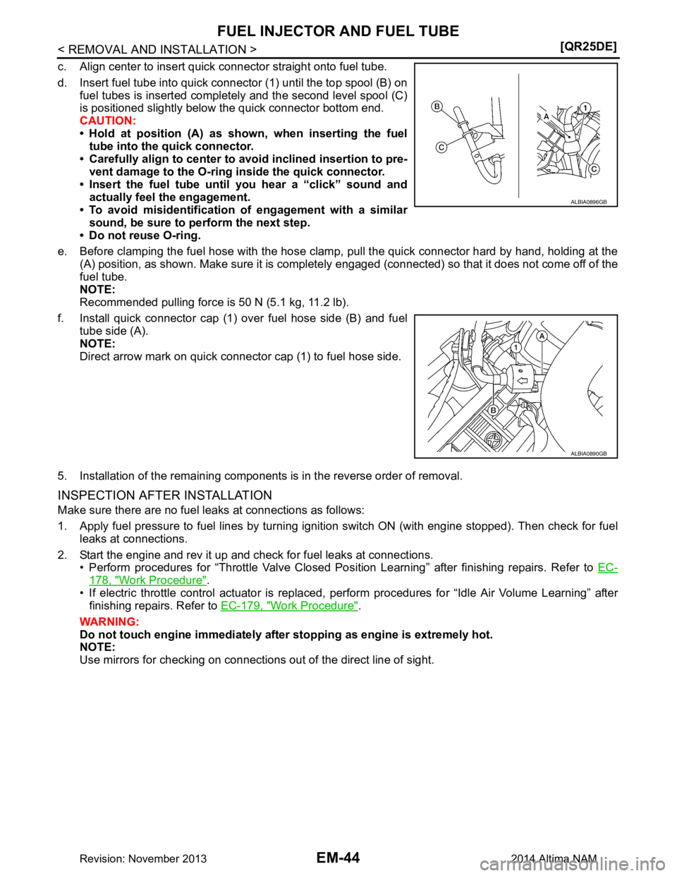
d. Insert fuel tube into quick connector (1) until the top spool (B) on fuel tubes is inserted completely and the second level spool (C)
is positioned slightly below the quick connector bottom end.
CAUTION:
• Hold at position (A) as show n, when inserting the fuel
tube into the quick connector.
• Carefully align to center to avoid inclined insertion to pre-
vent damage to the O-ring inside the quick connector.
• Insert the fuel tube until you hear a “click” sound and
actually feel the engagement.
• To avoid misidentification of engagement with a similar
sound, be sure to perform the next step.
• Do not reuse O-ring.
e. Before clamping the fuel hose with the hose clamp, pull the quick connector hard by hand, holding at the
(A) position, as shown. Make sure it is completely engaged (connected) so that it does not come off of the
fuel tube.
NOTE:
Recommended pulling force is 50 N (5.1 kg, 11.2 lb).
f. Install quick connector cap (1) over fuel hose side (B) and fuel tube side (A).
NOTE:
Direct arrow mark on quick connector cap (1) to fuel hose side.
5. Installation of the remaining components is in the reverse order of removal.
INSPECTION AFTER INSTALLATION
Make sure there are no fuel leaks at connections as follows:
1. Apply fuel pressure to fuel lines by turning ignition switch ON (with engine stopped). Then check for fuel leaks at connections.
2. Start the engine and rev it up and check for fuel leaks at connections. • Perform procedures for “Throttle Valve Closed Posi tion Learning” after finishing repairs. Refer to EC-
178, "Work Procedure".
• If electric throttle control actuator is replaced, perform procedures for “Idle Air Volume Learning” after
finishing repairs. Refer to EC-179, "Work Procedure"
.
WARNING:
Do not touch engine immediately after stopping as engine is extremely hot.
NOTE:
Use mirrors for checking on connections out of the direct line of sight.
ALBIA0896GB
ALBIA0890GB
Revision: November 20132014 Altima NAM
Page 2048 of 4801
EM-50
< REMOVAL AND INSTALLATION >[QR25DE]
CAMSHAFT
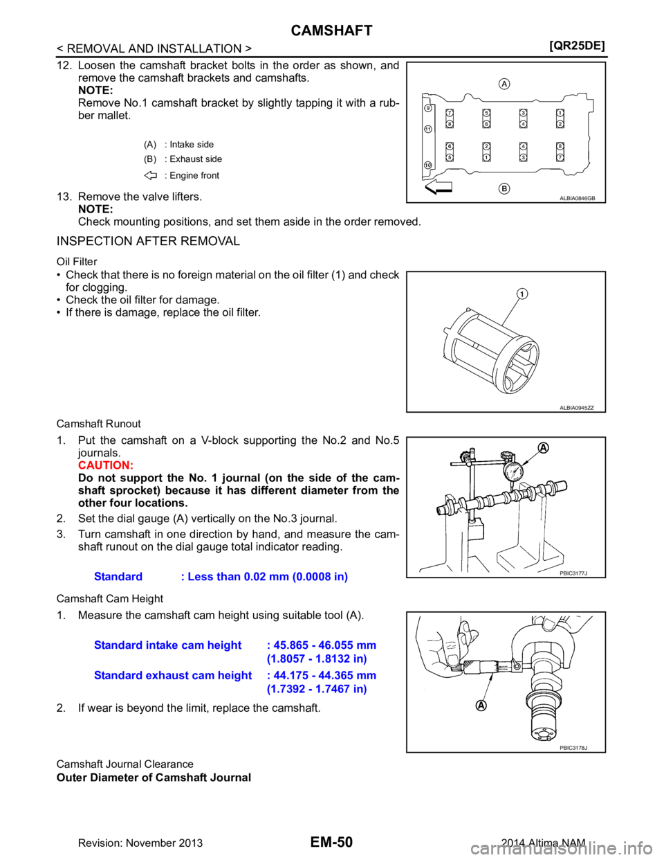
12. Loosen the camshaft bracket bolts in the order as shown, and
remove the camshaft brackets and camshafts.
NOTE:
Remove No.1 camshaft bracket by slightly tapping it with a rub-
ber mallet.
13. Remove the valve lifters. NOTE:
Check mounting positions, and set them aside in the order removed.
INSPECTION AFTER REMOVAL
Oil Filter
• Check that there is no foreign material on the oil filter (1) and check for clogging.
• Check the oil filter for damage.
• If there is damage, replace the oil filter.
Camshaft Runout
1. Put the camshaft on a V-block supporting the No.2 and No.5 journals.
CAUTION:
Do not support the No. 1 journal (on the side of the cam-
shaft sprocket) because it has different diameter from the
other four locations.
2. Set the dial gauge (A) vertically on the No.3 journal.
3. Turn camshaft in one direction by hand, and measure the cam- shaft runout on the dial gauge total indicator reading.
Camshaft Cam Height
1. Measure the camshaft cam height using suitable tool (A).
2. If wear is beyond the limit, replace the camshaft.
Camshaft Journal Clearance
Outer Diameter of Camshaft Journal
(A) : Intake side
(B) : Exhaust side
: Engine front
ALBIA0846GB
ALBIA0945ZZ
Standard : Less than 0.02 mm (0.0008 in)PBIC3177J
Standard intake cam height : 45.865 - 46.055 mm (1.8057 - 1.8132 in)
Standard exhaust cam height : 44.175 - 44.365 mm (1.7392 - 1.7467 in)
PBIC3178J
Revision: November 20132014 Altima NAM
Page 2076 of 4801
EM-78
< REMOVAL AND INSTALLATION >[QR25DE]
CYLINDER HEAD
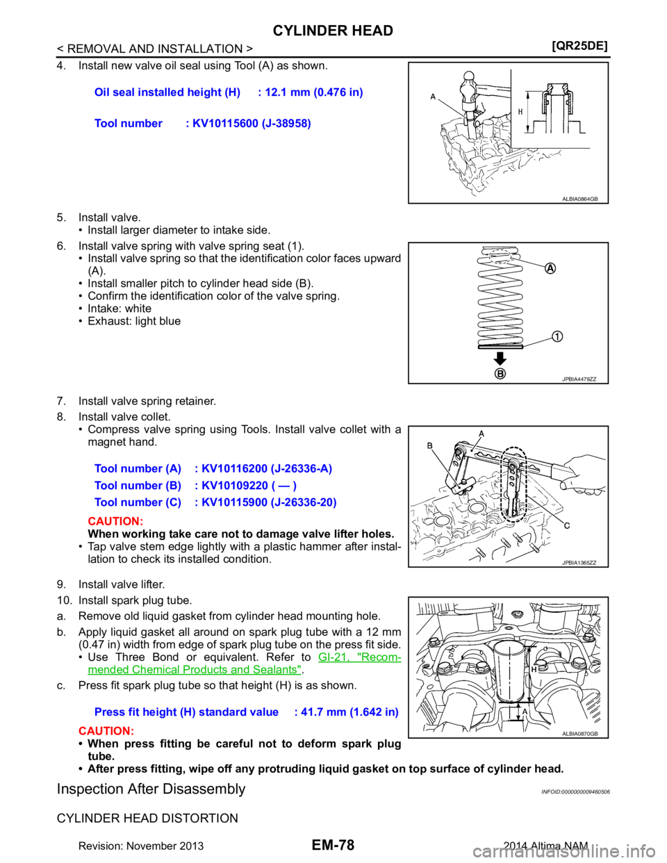
4. Install new valve oil seal using Tool (A) as shown.
5. Install valve. • Install larger diameter to intake side.
6. Install valve spring with valve spring seat (1). • Install valve spring so that the identification color faces upward
(A).
• Install smaller pitch to cylinder head side (B).
• Confirm the identification color of the valve spring.
• Intake: white
• Exhaust: light blue
7. Install valve spring retainer.
8. Install valve collet. • Compress valve spring using Tools. Install valve collet with amagnet hand.
CAUTION:
When working take care not to damage valve lifter holes.
• Tap valve stem edge lightly with a plastic hammer after instal-
lation to check its installed condition.
9. Install valve lifter.
10. Install spark plug tube.
a. Remove old liquid gasket from cylinder head mounting hole.
b. Apply liquid gasket all around on spark plug tube with a 12 mm (0.47 in) width from edge of spark plug tube on the press fit side.
• Use Three Bond or equivalent. Refer to GI-21, "Recom-
mended Chemical Products and Sealants".
c. Press fit spark plug tube so that height (H) is as shown.
CAUTION:
• When press fitting be careful not to deform spark plug
tube.
• After press fitting, wipe off any protruding liquid gasket on top surface of cylinder head.
Inspection After DisassemblyINFOID:0000000009460506
CYLINDER HEAD DISTORTION
Oil seal installed height (H) : 12.1 mm (0.476 in)
Tool number : KV10115600 (J-38958)
ALBIA0864GB
JPBIA4479ZZ
Tool number (A) : KV10116200 (J-26336-A)
Tool number (B) : KV10109220 ( — )
Tool number (C) : KV10115900 (J-26336-20)
JPBIA1365ZZ
Press fit height (H) standard value : 41.7 mm (1.642 in)
ALBIA0870GB
Revision: November 20132014 Altima NAM
Page 2101 of 4801
CYLINDER BLOCKEM-103
< UNIT DISASSEMBLY AND ASSEMBLY > [QR25DE]
C
D E
F
G H
I
J
K L
M A
EM
NP
O
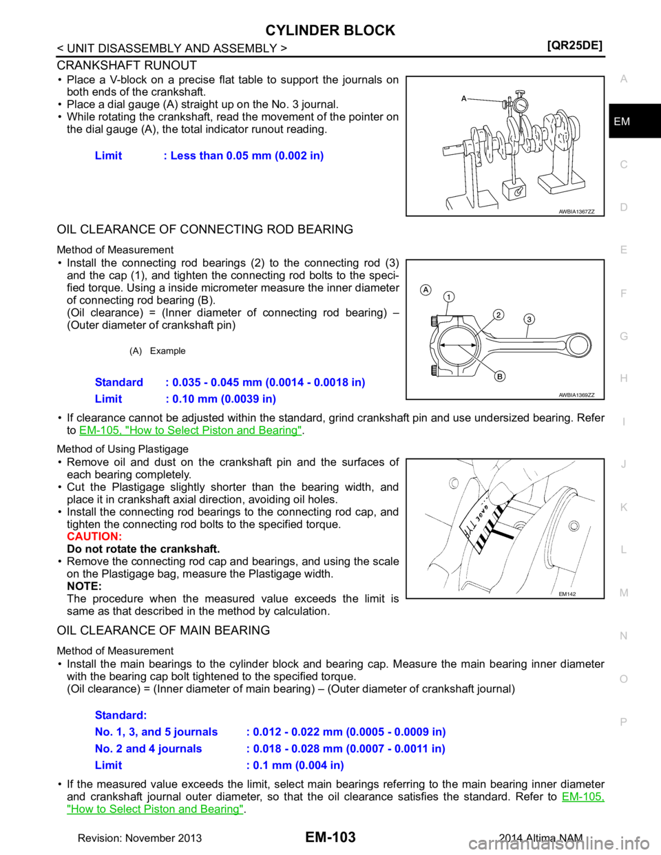
CRANKSHAFT RUNOUT
• Place a V-block on a precise flat table to support the journals on
both ends of the crankshaft.
• Place a dial gauge (A) straight up on the No. 3 journal.
• While rotating the crankshaft, read the movement of the pointer on the dial gauge (A), the total indicator runout reading.
OIL CLEARANCE OF CONNECTING ROD BEARING
Method of Measurement
• Install the connecting rod bearings (2) to the connecting rod (3)
and the cap (1), and tighten the c onnecting rod bolts to the speci-
fied torque. Using a inside micrometer measure the inner diameter
of connecting rod bearing (B).
(Oil clearance) = (Inner diameter of connecting rod bearing) –
(Outer diameter of crankshaft pin)
• If clearance cannot be adjusted within the standard, grind crankshaft pin and use undersized bearing. Refer
to EM-105, "How to Select Piston and Bearing"
.
Method of Using Plastigage
• Remove oil and dust on the crankshaft pin and the surfaces of
each bearing completely.
• Cut the Plastigage slightly shorter than the bearing width, and place it in crankshaft axial direction, avoiding oil holes.
• Install the connecting rod bearings to the connecting rod cap, and tighten the connecting rod bolts to the specified torque.
CAUTION:
Do not rotate the crankshaft.
• Remove the connecting rod cap and bearings, and using the scale on the Plastigage bag, measure the Plastigage width.
NOTE:
The procedure when the measured value exceeds the limit is
same as that described in the method by calculation.
OIL CLEARANCE OF MAIN BEARING
Method of Measurement
• Install the main bearings to the cylinder block and bearing cap. Measure the main bearing inner diameter with the bearing cap bolt tightened to the specified torque.
(Oil clearance) = (Inner diameter of main beari ng) – (Outer diameter of crankshaft journal)
• If the measured value exceeds the limit, select main bearings referring to the main bearing inner diameter
and crankshaft journal outer diameter, so that t he oil clearance satisfies the standard. Refer to EM-105,
"How to Select Piston and Bearing".
Limit : Less than 0.05 mm (0.002 in)
AWBIA1367ZZ
(A) Example
Standard : 0.035 - 0.045 mm (0.0014 - 0.0018 in)
Limit : 0.10 mm (0.0039 in)
AWBIA1369ZZ
EM142
Standard:
No. 1, 3, and 5 journals : 0.012 - 0.022 mm (0.0005 - 0.0009 in)
No. 2 and 4 journals : 0.018 - 0.028 mm (0.0007 - 0.0011 in)
Limit : 0.1 mm (0.004 in)
Revision: November 20132014 Altima NAM
Page 2102 of 4801
EM-104
< UNIT DISASSEMBLY AND ASSEMBLY >[QR25DE]
CYLINDER BLOCK
Method of Using Plastigage
• Remove oil and dust on the crankshaft journal and the surfaces of
each bearing completely.
• Cut the Plastigage slightly shorter than the bearing width, and
place it in crankshaft axial direction, avoiding oil holes.
• Tighten the main bearing bolts to the specified torque. CAUTION:
Do not rotate the crankshaft.
• Remove the bearing cap and bearings, and using the scale on the Plastigage bag, measure the Plastigage width.
NOTE:
The procedure when the measured value exceeds the limit is
same as that described in the "Method by Calculation".
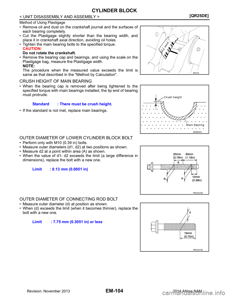
CRUSH HEIGHT OF MAIN BEARING
• When the bearing cap is removed after being tightened to the specified torque with main bearings installed, the tip end of bearing
must protrude.
• If the standard is not met, replace main bearings.
OUTER DIAMETER OF LOWER CYLINDER BLOCK BOLT
• Perform only with M10 (0.39 in) bolts.
• Measure outer diameters (d1, d2) at two positions as shown.
• Measure d2 at a point within area (A) as shown.
• When the value of d1- d2 exceeds the limit (a large difference in dimensions), replace the bolt with a new one.
OUTER DIAMETER OF CONNECTING ROD BOLT
• Measure outer diameter (d) at position as shown.
• When (d) exceeds the limit (when it becomes thinner), replace the
bolt with a new one.
EM142
Standard : There must be crush height.
SEM502G
Limit : 0.13 mm (0.0051 in)
PBIC0272E
Limit : 7.75 mm (0.3051 in) or less
PBIC0273E
Revision: November 20132014 Altima NAM
Page 2112 of 4801
EM-114
< SERVICE DATA AND SPECIFICATIONS (SDS) [QR25DE]
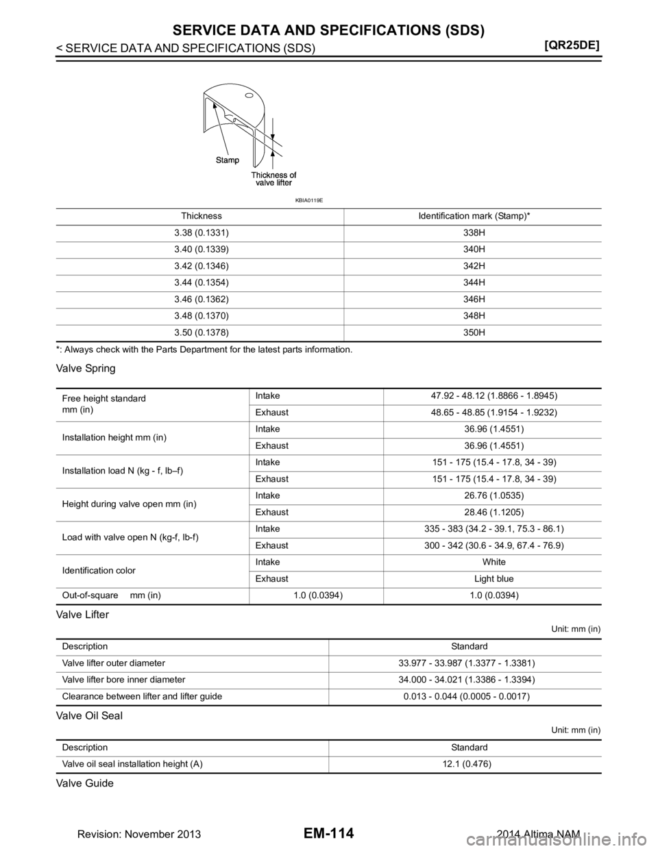
SERVICE DATA AND SPECIFICATIONS (SDS)
*: Always check with the Parts Department for the latest parts information.
Valve Spring
Valve Lifter
Unit: mm (in)
Valve Oil Seal
Unit: mm (in)
Valve Guide
3.38 (0.1331) 338H
3.40 (0.1339) 340H
3.42 (0.1346) 342H
3.44 (0.1354) 344H
3.46 (0.1362) 346H
3.48 (0.1370) 348H
3.50 (0.1378) 350H Thickness Identification mark (Stamp)*
KBIA0119E
Free height standard
mm (in) Intake 47.92 - 48.12 (1.8866 - 1.8945)
Exhaust 48.65 - 48.85 (1.9154 - 1.9232)
Installation height mm (in) Intake 36.96 (1.4551)
Exhaust 36.96 (1.4551)
Installation load N (kg - f, lb–f) Intake 151 - 175 (15.4 - 17.8, 34 - 39)
Exhaust 151 - 175 (15.4 - 17.8, 34 - 39)
Height during valve open mm (in) Intake 26.76 (1.0535)
Exhaust 28.46 (1.1205)
Load with valve open N (kg-f, lb-f) Intake 335 - 383 (34.2 - 39.1, 75.3 - 86.1)
Exhaust 300 - 342 (30.6 - 34.9, 67.4 - 76.9)
Identification color Intake White
Exhaust Light blue
Out-of-square mm (in) 1.0 (0.0394) 1.0 (0.0394)
Description Standard
Valve lifter outer diameter 33.977 - 33.987 (1.3377 - 1.3381)
Valve lifter bore inner diameter 34.000 - 34.021 (1.3386 - 1.3394)
Clearance between lifter and lifter guide 0.013 - 0.044 (0.0005 - 0.0017)
Description Standard
Valve oil seal installation height (A) 12.1 (0.476)
Revision: November 20132014 Altima NAM
Page 2122 of 4801
EM-124
< PRECAUTION >[VQ35DE]
PRECAUTIONS
• When tightening nuts and bolts, as a basic rule, equally tighten in several different steps starting with the
ones in center, then ones on inside and outside diagonally in this order. If the order of tightening is specified,
do exactly as specified.
• Replace with new gasket, packing, oil seal or O-ring.
• Thoroughly wash, clean, and air-blow each part. Carefully check oil or coolant passages for any restriction and blockage.
• Avoid damaging sliding or mating surfaces. Completely remove foreign materials such as cloth lint or dust. Before assembly, oil sliding surfaces well.
• Release air within route after draining coolant.
• Before starting engine, apply fuel pressure to fuel li nes with turning ignition switch ON (with engine stopped).
Then make sure that there are no leaks at fuel line connections.
• After repairing, start engine and increase engine speed to check coolant, fuel, oil, and exhaust systems for leakage.
Parts Requiring Angular TighteningINFOID:0000000009460520
• Use an angle wrench for the final tightening of the following engine parts:
- Cylinder head bolts
- Main bearing cap bolts
- Connecting rod cap nuts
- Crankshaft pulley bolt (No angle wrench is required as the bolt flange is provided with notches for angular
tightening)
• Do not use a torque value for final tightening.
• The torque value for these parts are for a preliminary step.
• Ensure thread and seat surfaces are clean and coated with engine oil.
Precaution for Liquid GasketINFOID:0000000009460521
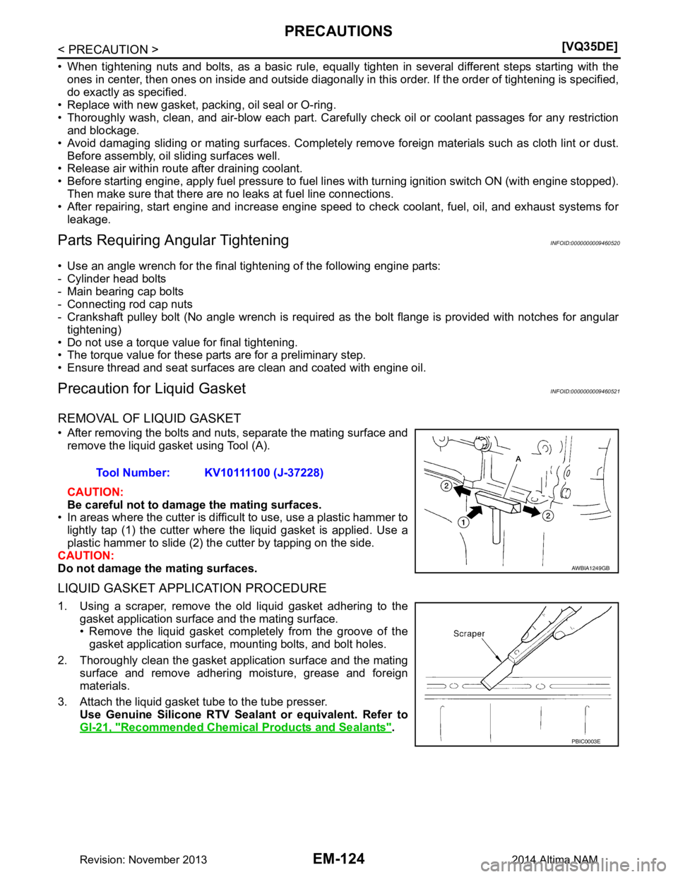
REMOVAL OF LIQUID GASKET
• After removing the bolts and nuts, separate the mating surface and remove the liquid gasket using Tool (A).
CAUTION:
Be careful not to damage the mating surfaces.
• In areas where the cutter is difficult to use, use a plastic hammer to lightly tap (1) the cutter where the liquid gasket is applied. Use a
plastic hammer to slide (2) the cutter by tapping on the side.
CAUTION:
Do not damage the mating surfaces.
LIQUID GASKET APPLICATION PROCEDURE
1. Using a scraper, remove the old liquid gasket adhering to the gasket application surface and the mating surface.
• Remove the liquid gasket completely from the groove of the
gasket application surface, mounting bolts, and bolt holes.
2. Thoroughly clean the gasket application surface and the mating surface and remove adhering moisture, grease and foreign
materials.
3. Attach the liquid gasket tube to the tube presser. Use Genuine Silicone RTV Seal ant or equivalent. Refer to
GI-21, "Recommended Chemi cal Products and Sealants"
.
Tool Number: KV10111100 (J-37228)
AWBIA1249GB
PBIC0003E
Revision: November 20132014 Altima NAM
Page 2150 of 4801
EM-152
< REMOVAL AND INSTALLATION >[VQ35DE]
EXHAUST MANIFOLD AND THREE WAY CATALYST
Removal and Installation (LH)
INFOID:0000000009460546
REMOVAL
WARNING:
• Perform the work when the exhaust system has completely cooled down.
• When removing the front and rear engine mounting th rough bolts and nuts, lift the engine up slightly
for safety.
NOTE:
When removing components such as hoses, tubes/lines, etc. , cap or plug openings to prevent fluid from spill-
ing.
1. Remove the air cleaner assembly, and air duct hose and resonator assembly. Refer to EM-144, "Removal
and Installation".
2. Remove the battery and battery tray assembly. Refer to PG-74, "Removal and Installation (Battery Tray)"
.
3. Remove the engine under cover. Refer to EXT-28, "Removal and Installation"
.
4. Remove the radiator assembly. Refer to CO-41, "Removal and Installation"
.
5. Remove the engine cooling fan shroud and motor assembly. Refer to CO-42, "Removal and Installation"
.
6. Remove the front exhaust tube. Refer to EX-10, "Exploded View"
.
7. Remove the LH three way catalyst support brackets.
8. Remove heated oxygen sensor 2 (bank 2), air fuel ratio (A/F) sensor 1 (bank 2).
a. Remove harness connector of each sensor, and di sconnect the harness from the bracket and middle
clamp.
b. Remove both heated oxygen sensor 2 and air fuel ratio (A/F) sensor 1 using Tool.
CAUTION:
• Be careful not to damage heated oxygen sen sors 2 or air fuel ratio (A/F) sensors 1.
• Discard any heated oxygen sensor 2 which has been dropped from a height of more than 0.5 m
(19.7 in) onto a hard surface such as a co ncrete floor; replace with a new sensor.
9. Remove exhaust manifold heat shield (LH) and three way catalyst heat shields (LH) using power tool.
10. Remove the three way catalyst (bank 2) by loosening the bolts first and then removing the nuts and through bolts.
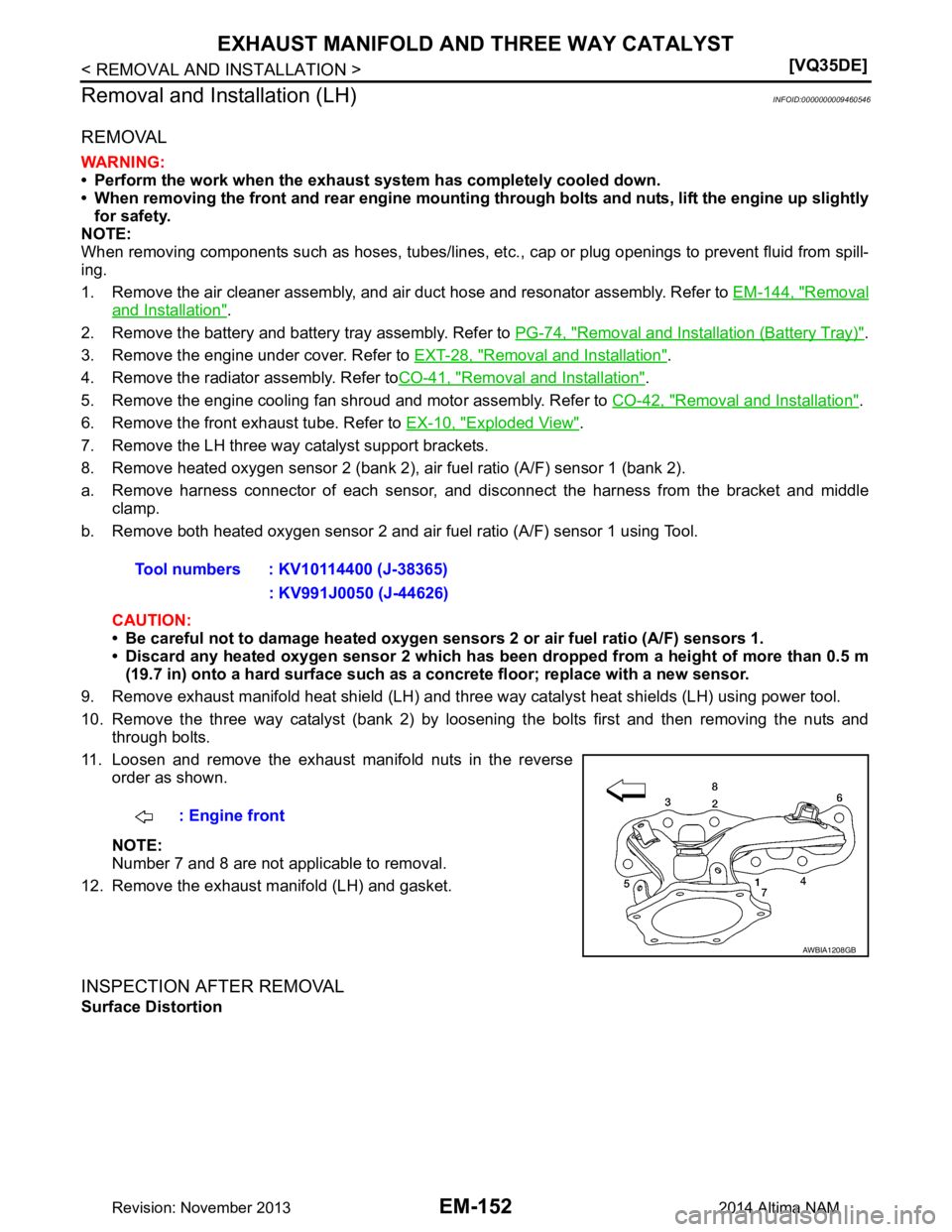
11. Loosen and remove the exhaust manifold nuts in the reverse order as shown.
NOTE:
Number 7 and 8 are not applicable to removal.
12. Remove the exhaust manifold (LH) and gasket.
INSPECTION AFTER REMOVAL
Surface Distortion Tool numbers : KV10114400 (J-38365)
: KV991J0050 (J-44626)
: Engine front
AWBIA1208GB
Revision: November 20132014 Altima NAM
Page 2152 of 4801
EM-154
< REMOVAL AND INSTALLATION >[VQ35DE]
EXHAUST MANIFOLD AND THREE WAY CATALYST
• Perform the work when the exhaust and co
oling system have completely cooled down.
• When removing the front and rear engine mounting th rough bolts and nuts, lift the engine up slightly
for safety. For engine slingers, refer to EM-220, "Removal and Installation"
.
1. Remove the engine and transaxle assembly. Refer to EM-220, "Removal and Installation"
.
2. Remove the RH three way catalyst supports.
3. Remove rear engine mount bracket. Refer to EM-220, "Removal and Installation"
.
4. Remove heated oxygen sensor 2 (bank 1), air fuel ratio (A/F) sensor 1 (bank 1).
a. Remove harness connector from heated oxygen sensor 2 and air fuel ration (A/F) sensor 1, and discon-
nect the harness from the bracket and middle clamp.
b. Remove both heated oxygen sensors 2 and air fuel ratio (A/F) sensors 1 using Tool.
CAUTION:
• Be careful not to damage heated oxygen sen sors 2 or air fuel ratio (A/F) sensors 1.
• Discard any heated oxygen sensor 2 which has been dropped from a height of more than 0.5 m
(19.7 in) onto a hard surface such as a co ncrete floor; replace with a new sensor.
5. Remove exhaust manifold heat shield (RH) and three way catalyst heat shields (RH) using power tool.
6. Remove the three way catalyst (bank 1) by loosening the bolts first and then removing the nuts and through bolts.
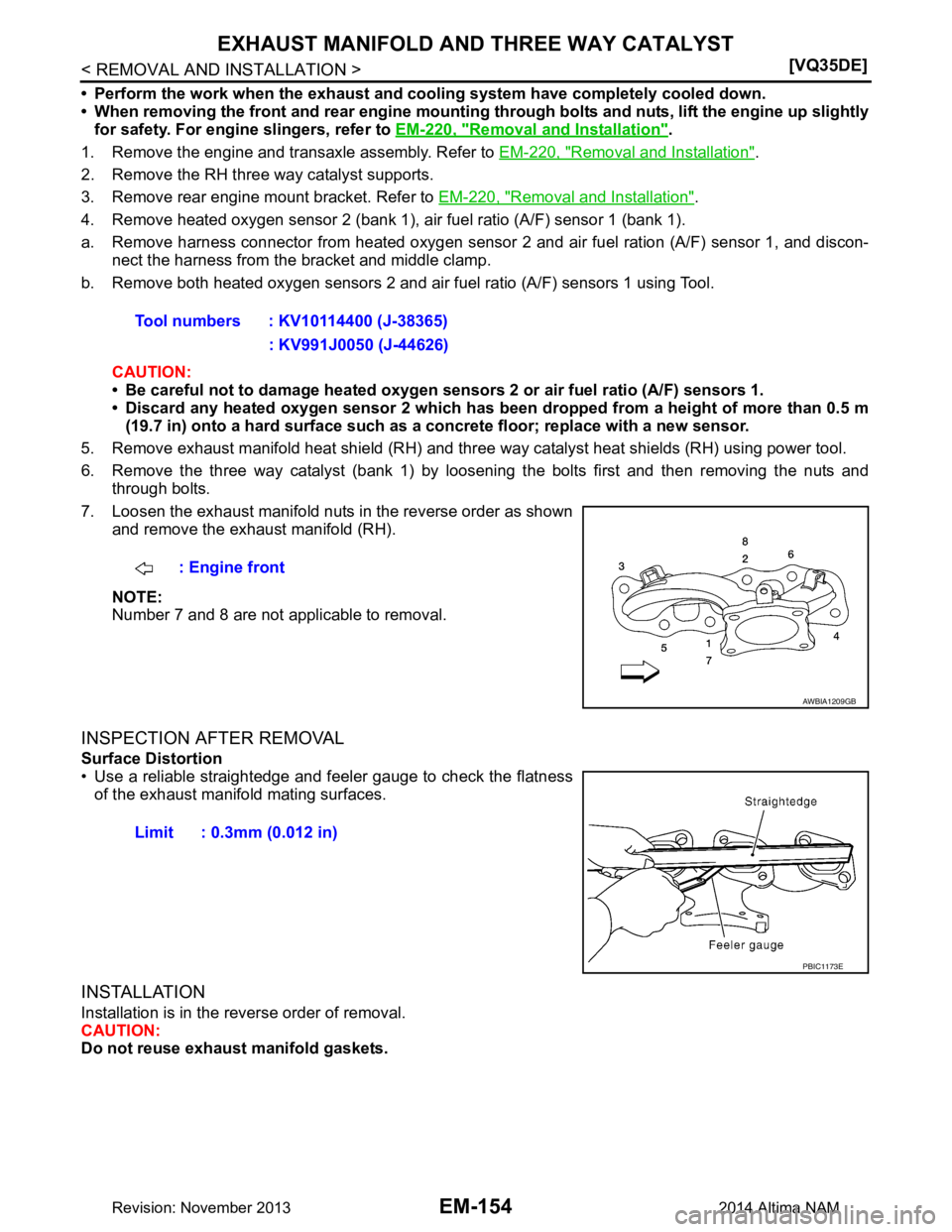
7. Loosen the exhaust manifold nuts in the reverse order as shown and remove the exhaust manifold (RH).
NOTE:
Number 7 and 8 are not applicable to removal.
INSPECTION AFTER REMOVAL
Surface Distortion
• Use a reliable straightedge and feeler gauge to check the flatness of the exhaust manifold mating surfaces.
INSTALLATION
Installation is in the reverse order of removal.
CAUTION:
Do not reuse exhaust manifold gaskets. Tool numbers : KV10114400 (J-38365)
: KV991J0050 (J-44626)
: Engine front
AWBIA1209GB
Limit : 0.3mm (0.012 in)
PBIC1173E
Revision: November 20132014 Altima NAM