timing NISSAN TEANA 2014 Service Manual
[x] Cancel search | Manufacturer: NISSAN, Model Year: 2014, Model line: TEANA, Model: NISSAN TEANA 2014Pages: 4801, PDF Size: 51.2 MB
Page 2192 of 4801
EM-194
< REMOVAL AND INSTALLATION >[VQ35DE]
CAMSHAFT
CAMSHAFT
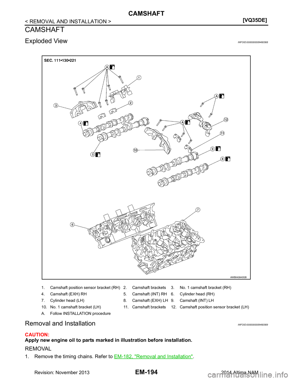
Exploded ViewINFOID:0000000009460568
Removal and InstallationINFOID:0000000009460569
CAUTION:
Apply new engine oil to parts marked in illustration before installation.
REMOVAL
1. Remove the timing chains. Refer to EM-182, "Removal and Installation".
1. Camshaft position sensor bracket (RH) 2. Camshaft brackets 3. No. 1 camshaft bracket (RH)
4. Camshaft (EXH) RH 5. Camshaft (INT) RH 6. Cylinder head (RH)
7. Cylinder head (LH) 8. Camshaft (EXH) LH 9. Camshaft (INT) LH
10. No. 1 camshaft bracket (LH) 11. Camshaft brackets 12. Camshaft position sensor bracket (LH)
A. Follow INSTALLATION procedure
AWBIA0840GB
Revision: November 20132014 Altima NAM
Page 2193 of 4801
CAMSHAFTEM-195
< REMOVAL AND INSTALLATION > [VQ35DE]
C
D E
F
G H
I
J
K L
M A
EM
NP
O
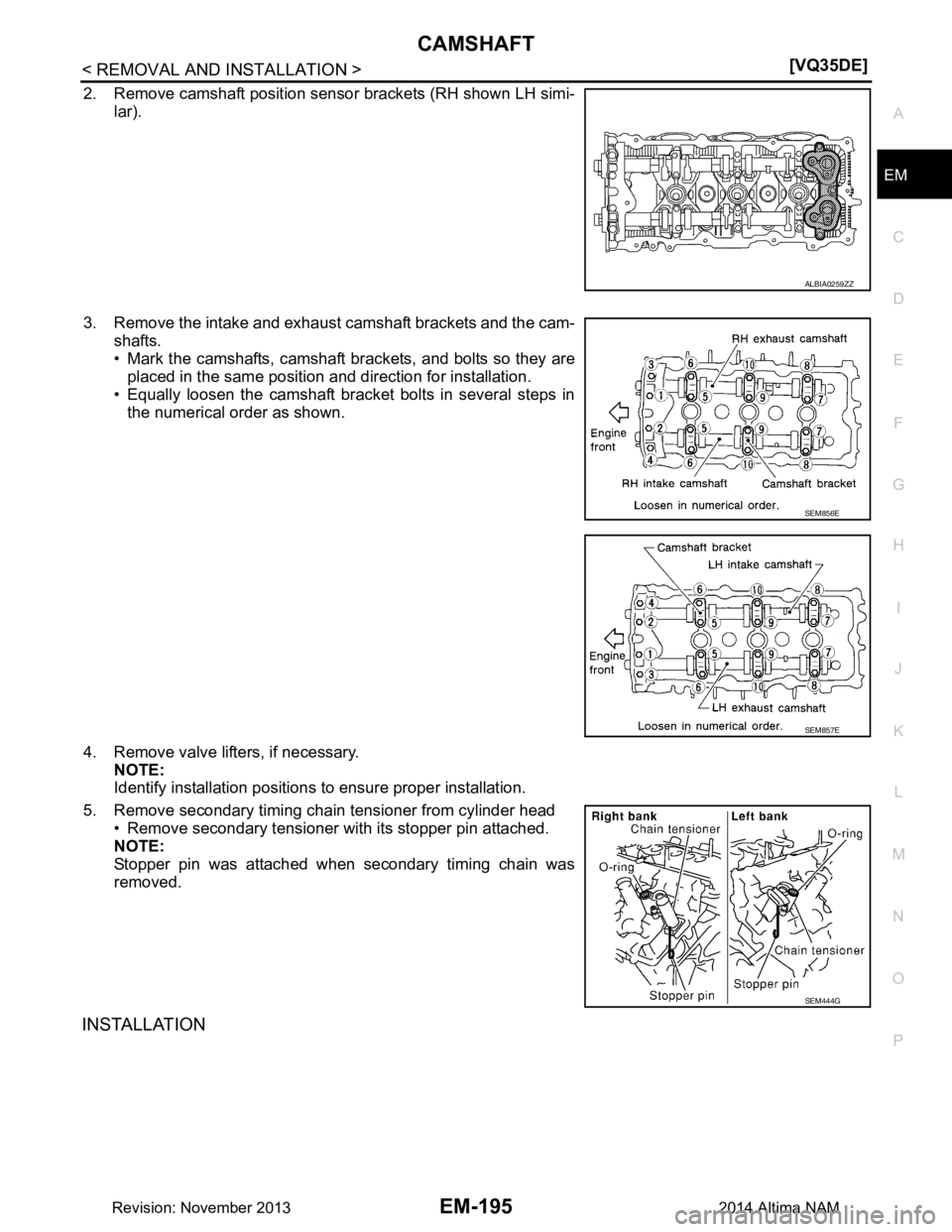
2. Remove camshaft position sensor brackets (RH shown LH simi-
lar).
3. Remove the intake and exhaust camshaft brackets and the cam- shafts.
• Mark the camshafts, camshaft brackets, and bolts so they are
placed in the same position and direction for installation.
• Equally loosen the camshaft bracket bolts in several steps in the numerical order as shown.
4. Remove valve lifters, if necessary. NOTE:
Identify installation positions to ensure proper installation.
5. Remove secondary timing chain tensioner from cylinder head • Remove secondary tensioner with its stopper pin attached.
NOTE:
Stopper pin was attached when secondary timing chain was
removed.
INSTALLATION
ALBIA0259ZZ
SEM856E
SEM857E
SEM444G
Revision: November 20132014 Altima NAM
Page 2197 of 4801
CAMSHAFTEM-199
< REMOVAL AND INSTALLATION > [VQ35DE]
C
D E
F
G H
I
J
K L
M A
EM
NP
O
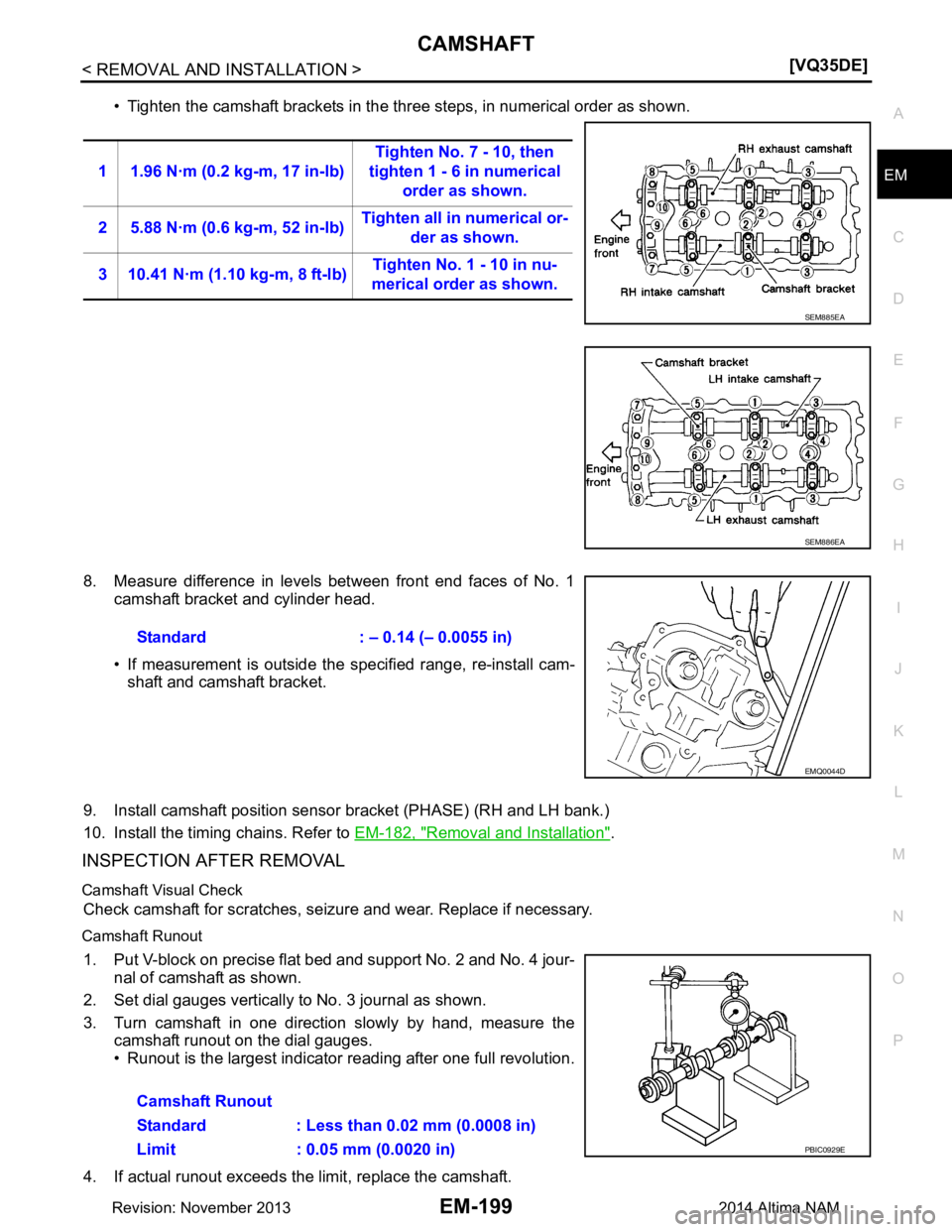
• Tighten the camshaft brackets in the three steps, in numerical order as shown.
8. Measure difference in levels between front end faces of No. 1 camshaft bracket and cylinder head.
• If measurement is outside the specified range, re-install cam-
shaft and camshaft bracket.
9. Install camshaft position sensor bracket (PHASE) (RH and LH bank.)
10. Install the timing chains. Refer to EM-182, "Removal and Installation"
.
INSPECTION AFTER REMOVAL
Camshaft Visual Check
Check camshaft for scratches, seizure and wear. Replace if necessary.
Camshaft Runout
1. Put V-block on precise flat bed and support No. 2 and No. 4 jour-
nal of camshaft as shown.
2. Set dial gauges vertically to No. 3 journal as shown.
3. Turn camshaft in one direction slowly by hand, measure the camshaft runout on the dial gauges.
• Runout is the largest indicator reading after one full revolution.
4. If actual runout exceeds th e limit, replace the camshaft.
1 1.96 N·m (0.2 kg-m, 17 in-lb)
Tighten No. 7 - 10, then
tighten 1 - 6 in numerical order as shown.
2 5.88 N·m (0.6 kg-m, 52 in-lb) Tighten all in numerical or-
der as shown.
3 10.41 N·m (1.10 kg-m, 8 ft-lb) Tighten No. 1 - 10 in nu-
merical order as shown.
SEM885EA
SEM886EA
Standard : – 0.14 (– 0.0055 in)
EMQ0044D
Camshaft Runout
Standard : Less than 0.02 mm (0.0008 in)
Limit : 0.05 mm (0.0020 in)
PBIC0929E
Revision: November 20132014 Altima NAM
Page 2200 of 4801
EM-202
< REMOVAL AND INSTALLATION >[VQ35DE]
CAMSHAFT
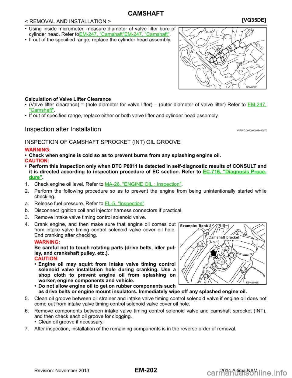
• Using inside micrometer, measure diameter of valve lifter bore of
cylinder head. Refer to EM-247, "Camshaft"
EM-247, "Camshaft".
• If out of the specified range, replace the cylinder head assembly.
Calculation of Valve Lifter Clearance
• (Valve lifter clearance) = (hole diameter for valve li fter) – (outer diameter of valve lifter) Refer to EM-247,
"Camshaft".
• If out of specified range, replace either or both valve lifter and cylinder head assembly.
Inspection after InstallationINFOID:0000000009460570
INSPECTION OF CAMSHAFT SPROCKET (INT) OIL GROOVE
WARNING:
• Check when engine is cold so as to pr event burns from any splashing engine oil.
CAUTION:
• Perform this inspection only when DTC P0011 is detected in self-diagnostic results of CONSULT and
it is directed according to inspection procedure of EC section. Refer to EC-716, "Diagnosis Proce-
dure".
1. Check engine oil level. Refer to MA-26, "ENGINE OIL : Inspection"
.
2. Perform the following procedure so as to prevent the engine from being unintentionally started while
checking.
a. Release fuel pressure. Refer to FL-5, "Inspection"
.
b. Disconnect ignition coil and injector harness connectors if practical.
3. Remove intake valve timing control solenoid valve.
4. Crank engine, and then make sure that engine oil comes out from intake valve timing control solenoid valve cover oil hole.
End cranking after checking.
WARNING:
Be careful not to touch rotating parts (drive belts, idler pul-
ley, and crankshaft pulley, etc.).
CAUTION:
• Engine oil may squirt from intake valve timing control solenoid valve installation hole during cranking. Use a
shop cloth to prevent engi ne oil from splashing on
worker, engine components and vehicle.
• Do not allow engine oil to get on rubber components such
as drive belts or engine mount insulators. I mmediately wipe off any splashed engine oil.
5. Clean oil groove between oil strainer and intake valve timing control solenoid valve if engine oil does not come out from intake valve timing control solenoid valve cover oil hole.
6. Remove components between intake valve timing c ontrol solenoid valve and camshaft sprocket (INT),
and then check each oil groove for clogging.
• Clean oil groove if necessary.
7. After inspection, installation of the remaining components is in the reverse order of removal.
SEM867E
KBIA2686E
Revision: November 20132014 Altima NAM
Page 2201 of 4801
OIL SEALEM-203
< REMOVAL AND INSTALLATION > [VQ35DE]
C
D E
F
G H
I
J
K L
M A
EM
NP
O
OIL SEAL
Removal and Installation of Valve Oil SealINFOID:0000000009460571
REMOVAL
1. Turn crankshaft until the cylinder requiring new oil seal
s is at TDC. This will prevent valve from dropping
into cylinder.
CAUTION:
When rotating crankshaft, be careful to avoid scarring the front cover with the timing chain.
2. Remove camshaft relating to valve oil seal to be removed. Refer to EM-194, "Removal and Installation"
.
3. Remove valve lifters. Refer to EM-210, "Disassembly and Assembly"
.
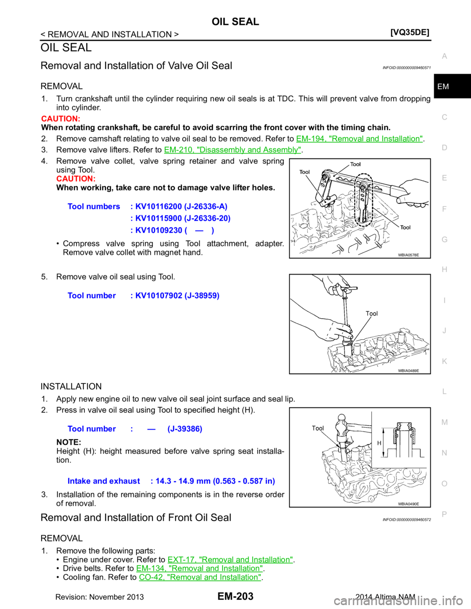
4. Remove valve collet, valve spring retainer and valve spring using Tool.
CAUTION:
When working, take care not to damage valve lifter holes.
• Compress valve spring using Tool attachment, adapter. Remove valve collet with magnet hand.
5. Remove valve oil seal using Tool.
INSTALLATION
1. Apply new engine oil to new valve oil seal joint surface and seal lip.
2. Press in valve oil seal using Tool to specified height (H).
NOTE:
Height (H): height measured before valve spring seat installa-
tion.
3. Installation of the remaining components is in the reverse order of removal.
Removal and Installati on of Front Oil SealINFOID:0000000009460572
REMOVAL
1. Remove the following parts:
• Engine under cover. Refer to EXT-17, "Removal and Installation"
.
• Drive belts. Refer to EM-134, "Removal and Installation"
.
• Cooling fan. Refer to CO-42, "Removal and Installation"
.
Tool numbers : KV10116200 (J-26336-A)
: KV10115900 (J-26336-20)
: KV10109230 ( — )
WBIA0578E
Tool number : KV10107902 (J-38959)
WBIA0489E
Tool number : — (J-39386)
Intake and exhaust : 14.3 - 14.9 mm (0.563 - 0.587 in)
WBIA0490E
Revision: November 20132014 Altima NAM
Page 2202 of 4801
EM-204
< REMOVAL AND INSTALLATION >[VQ35DE]
OIL SEAL
2. Remove the crankshaft pulley as follows:
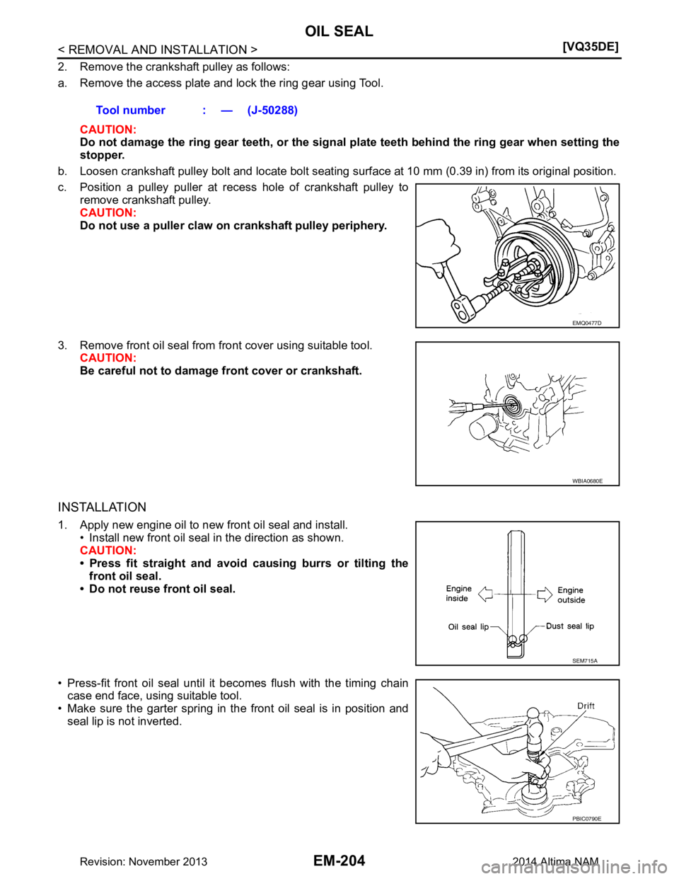
a. Remove the access plate and lock the ring gear using Tool.
CAUTION:
Do not damage the ring gear teeth, or the signal plate teeth behind the ring gear when setting the
stopper.
b. Loosen crankshaft pulley bolt and locate bolt seating surface at 10 mm (0.39 in) from its original position.
c. Position a pulley puller at recess hole of crankshaft pulley to remove crankshaft pulley.
CAUTION:
Do not use a puller claw on crankshaft pulley periphery.
3. Remove front oil seal from front cover using suitable tool. CAUTION:
Be careful not to damage front cover or crankshaft.
INSTALLATION
1. Apply new engine oil to new front oil seal and install.
• Install new front oil seal in the direction as shown.
CAUTION:
• Press fit straight and avoid causing burrs or tilting the
front oil seal.
• Do not reuse front oil seal.
• Press-fit front oil seal until it becomes flush with the timing chain
case end face, using suitable tool.
• Make sure the garter spring in the front oil seal is in position and seal lip is not inverted. Tool number : — (J-50288)
EMQ0477D
WBIA0680E
SEM715A
PBIC0790E
Revision: November 20132014 Altima NAM
Page 2205 of 4801
CYLINDER HEADEM-207
< REMOVAL AND INSTALLATION > [VQ35DE]
C
D E
F
G H
I
J
K L
M A
EM
NP
O
CYLINDER HEAD
Exploded ViewINFOID:0000000009460574
Removal and InstallationINFOID:0000000009460575
REMOVAL
1. Remove the rear timing chain case. Refer to
EM-189, "Removal and Installation".
2. Remove the intake manifold. Refer to EM-149, "Removal and Installation"
.
3. Remove the intake and exhaust camshafts. Refer to EM-194, "Removal and Installation"
.
4. Remove exhaust manifolds. Refer to EM-153, "Removal and Installation (RH)"
.
5. Remove the coolant outlet housing. Refer to CO-51, "Removal and Installation"
.
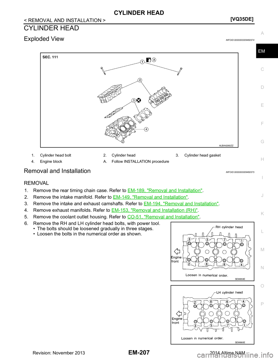
6. Remove the RH and LH cylinder head bolts, with power tool. • The bolts should be loosened gradually in three stages.
• Loosen the bolts in the numerical order as shown.
1. Cylinder head bolt 2. Cylinder head 3. Cylinder head gasket
4. Engine block A. Follow INSTALLATION procedure
ALBIA0260ZZ
SEM859E
SEM860E
Revision: November 20132014 Altima NAM
Page 2221 of 4801
ENGINE ASSEMBLYEM-223
< UNIT REMOVAL AND INSTALLATION > [VQ35DE]
C
D E
F
G H
I
J
K L
M A
EM
NP
O
• Start engine. With engine speed increased, check again for fuel leakage at connection points.
• Run engine to check for unusual noise and vibration. NOTE:
If hydraulic pressure inside timing chain tensioner dr ops after removal and installation, slack in the guide
may generate a pounding noise during and just after engine start. However, this is normal. Noise will stop
after hydraulic pressure rises.
• Warm up engine thoroughly to make sure there is no leak age of fuel, exhaust gas, or any oils/fluids including
engine oil and engine coolant.
• Bleed air from passages in lines and hoses, such as in cooling system.
• After cooling down engine, again check oil/fluid levels including engine oil and engine coolant. Refill to spec- ified level, if necessary.
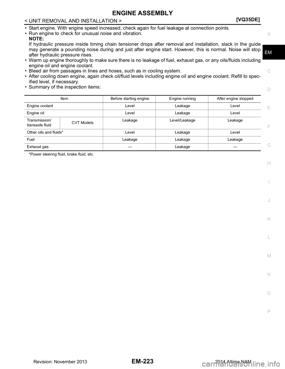
• Summary of the inspection items:
*Power steering fluid, brake fluid, etc. Item Before starting engine Engine running After engine stopped
Engine coolant Level Leakage Level
Engine oil Level Leakage Level
Transmission/
transaxle fluid CVT Models Leakage Level/Leakage Leakage
Other oils and fluids* Level Leakage Level
Fuel Leakage Leakage Leakage
Exhaust gas — Leakage —
Revision: November 20132014 Altima NAM
Page 2224 of 4801
EM-226
< UNIT DISASSEMBLY AND ASSEMBLY >[VQ35DE]
CYLINDER BLOCK
6. Drain the engine of all coolant and oil.
7. Remove the oil pan. Refer to EM-157, "Removal and Installation (Upper Oil Pan)"
.
8. Remove the timing chain primary and secondary. Refer to EM-182, "Removal and Installation"
.
9. Remove the cylinder head. Refer to EM-207, "Removal and Installation"
.
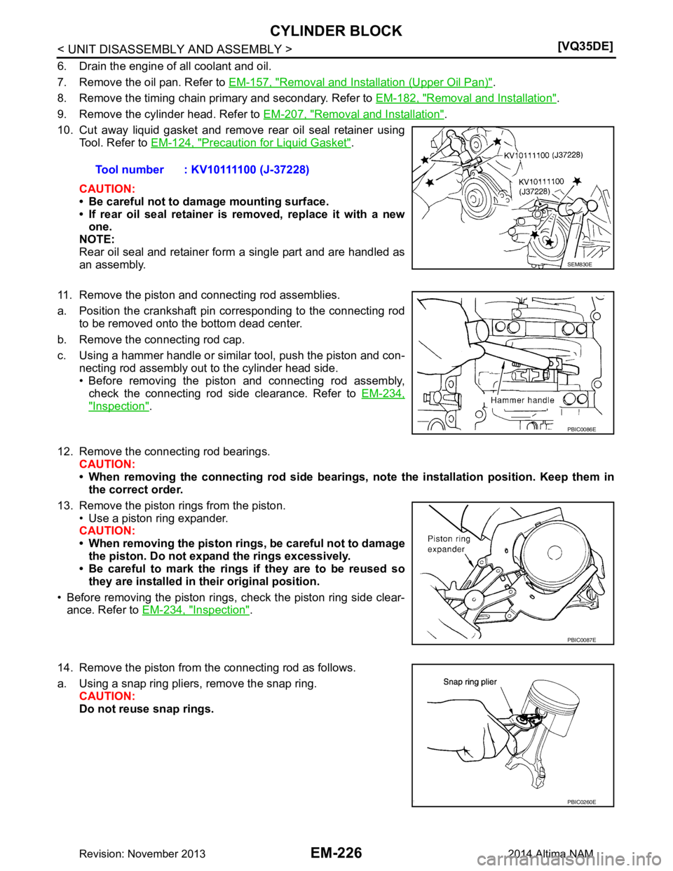
10. Cut away liquid gasket and remove rear oil seal retainer using Tool. Refer to EM-124, "Precaution for Liquid Gasket"
.
CAUTION:
• Be careful not to damage mounting surface.
• If rear oil seal retainer is removed, replace it with a new one.
NOTE:
Rear oil seal and retainer form a single part and are handled as
an assembly.
11. Remove the piston and connecting rod assemblies.
a. Position the crankshaft pin corresponding to the connecting rod to be removed onto the bottom dead center.
b. Remove the connecting rod cap.
c. Using a hammer handle or similar tool, push the piston and con- necting rod assembly out to the cylinder head side.
• Before removing the piston and connecting rod assembly, check the connecting rod side clearance. Refer to EM-234,
"Inspection".
12. Remove the connecting rod bearings. CAUTION:
• When removing the connecting rod side bearings, note the installation position. Keep them in
the correct order.
13. Remove the piston rings from the piston. • Use a piston ring expander.
CAUTION:
• When removing the piston rings, be careful not to damage the piston. Do not exp and the rings excessively.
• Be careful to mark the rings if they are to be reused so
they are installed in their original position.
• Before removing the piston rings, check the piston ring side clear- ance. Refer to EM-234, "Inspection"
.
14. Remove the piston from the connecting rod as follows.
a. Using a snap ring pliers, remove the snap ring. CAUTION:
Do not reuse snap rings. Tool number : KV10111100 (J-37228)
SEM830E
PBIC0086E
PBIC0087E
PBIC0260E
Revision: November 20132014 Altima NAM
Page 2232 of 4801
EM-234
< UNIT DISASSEMBLY AND ASSEMBLY >[VQ35DE]
CYLINDER BLOCK
17. Install the baffle plate to the main bearing beam.
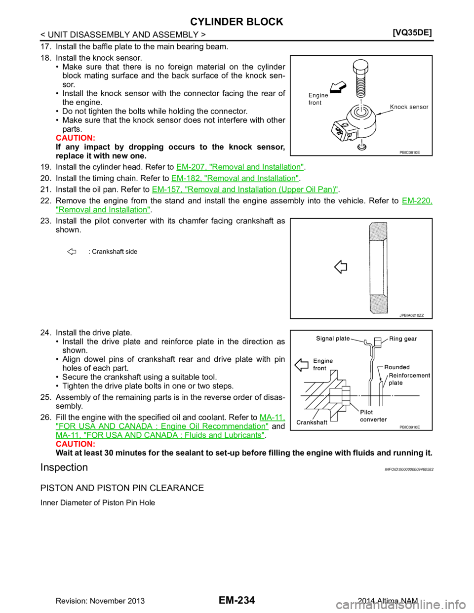
18. Install the knock sensor. • Make sure that there is no foreign material on the cylinder
block mating surface and the bac k surface of the knock sen-
sor.
• Install the knock sensor with the connector facing the rear of
the engine.
• Do not tighten the bolts while holding the connector.
• Make sure that the knock sensor does not interfere with other
parts.
CAUTION:
If any impact by dropping occurs to the knock sensor,
replace it with new one.
19. Install the cylinder head. Refer to EM-207, "Removal and Installation"
.
20. Install the timing chain. Refer to EM-182, "Removal and Installation"
.
21. Install the oil pan. Refer to EM-157, "Removal and Installation (Upper Oil Pan)"
.
22. Remove the engine from the stand and install the engine assembly into the vehicle. Refer to EM-220,
"Removal and Installation".
23. Install the pilot converter with its chamfer facing crankshaft as shown.
24. Install the drive plate. • Install the drive plate and reinforce plate in the direction asshown.
• Align dowel pins of crankshaft rear and drive plate with pin
holes of each part.
• Secure the crankshaft using a suitable tool.
• Tighten the drive plate bolts in one or two steps.
25. Assembly of the remaining parts is in the reverse order of disas- sembly.
26. Fill the engine with the specified oil and coolant. Refer to MA-11,
"FOR USA AND CANADA : Engine Oil Recommendation" and
MA-11, "FOR USA AND CANADA : Fluids and Lubricants"
.
CAUTION:
Wait at least 30 minutes for the sealant to set-up befo re filling the engine with fluids and running it.
InspectionINFOID:0000000009460582
PISTON AND PISTON PIN CLEARANCE
Inner Diameter of Piston Pin Hole
: Crankshaft side
PBIC0810E
JPBIA0210ZZ
PBIC0910E
Revision: November 20132014 Altima NAM