timing NISSAN TEANA 2014 Service Manual
[x] Cancel search | Manufacturer: NISSAN, Model Year: 2014, Model line: TEANA, Model: NISSAN TEANA 2014Pages: 4801, PDF Size: 51.2 MB
Page 2067 of 4801
TIMING CHAINEM-69
< REMOVAL AND INSTALLATION > [QR25DE]
C
D E
F
G H
I
J
K L
M A
EM
NP
O
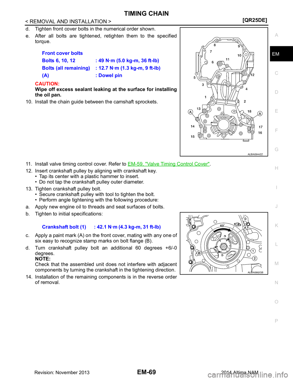
d. Tighten front cover bolts in the numerical order shown.
e. After all bolts are tightened, retighten them to the specified torque.
CAUTION:
Wipe off excess sealant leaking at the surface for installing
the oil pan.
10. Install the chain guide between the camshaft sprockets.
11. Install valve timing control cover. Refer to EM-59, "Valve Timing Control Cover"
.
12. Insert crankshaft pulley by aligning with crankshaft key. • Tap its center with a plastic hammer to insert.
• Do not tap the crankshaft pulley outer diameter.
13. Tighten crankshaft pulley bolt. • Secure crankshaft pulley with tool to tighten the bolt.
• Perform angle tightening with the following procedure:
a. Apply new engine oil to threads and seat surfaces of bolts.
b. Tighten to initial specifications:
c. Apply a paint mark (A) on the front cover, mating with any one of six easy to recognize stamp marks on bolt flange (B).
d. Turn crankshaft pulley bolt an additional 60 degrees +6/-0 degrees.
NOTE:
Check that the assembled unit does not interfere with adjacent
components by turning the crankshaft in the tightening direction.
14. Installation of the remaining components is in the reverse order of removal.Front cover bolts
Bolts 6, 10, 12 : 49 N·m (5.0 kg-m, 36 ft-lb)
Bolts (all remaining) : 12.7 N·m (1.3 kg-m, 9 ft-lb)
(A) : Dowel pin
ALBIA0944ZZ
Crankshaft bolt (1) : 42.1 N·m (4.3 kg-m, 31 ft-lb)
ALBIA0862GB
Revision: November 20132014 Altima NAM
Page 2068 of 4801
EM-70
< REMOVAL AND INSTALLATION >[QR25DE]
OIL SEAL
OIL SEAL
Removal and Installation
of Valve Oil SealINFOID:0000000009460500
REMOVAL
1. Remove camshaft. Refer to EM-47, "Removal and Installation".
2. Remove valve lifter. Refer to EM-47, "Removal and Installation"
.
3. Rotate crankshaft, and set piston whose oil seal is to removed to top dead center. This prevents valve from dropping inside cylinder.
CAUTION:
When rotating crankshaft, be careful to avoid scarring the front cover with the timing chain.
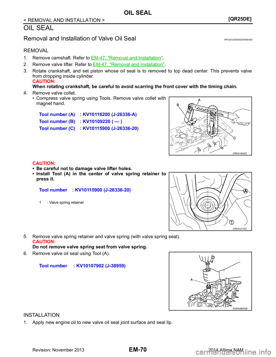
4. Remove valve collet. • Compress valve spring using Tools. Remove valve collet with
magnet hand.
CAUTION:
• Be careful not to damage valve lifter holes.
• Install Tool (A) in the center of valve spring retainer to
press it.
5. Remove valve spring retainer and valve spring (with valve spring seat). CAUTION:
Do not remove valve spring seat from valve spring.
6. Remove valve oil seal using Tool (A).
INSTALLATION
1. Apply new engine oil to new valve oil seal joint surface and seal lip. Tool number (A) : KV10116200 (J-26336-A)
Tool number (B) : KV10109220 ( — )
Tool number (C) : KV10115900 (J-26336-20)
JPBIA1365ZZ
Tool number : KV10115900 (J-26336-20)
1 : Valve spring retainer
JPBIA4477ZZ
Tool number : KV10107902 (J-38959)
ALBIA0863GB
Revision: November 20132014 Altima NAM
Page 2072 of 4801
EM-74
< REMOVAL AND INSTALLATION >[QR25DE]
CYLINDER HEAD
CYLINDER HEAD
Exploded ViewINFOID:0000000009460503
Removal and InstallationINFOID:0000000009460504
REMOVAL
1. Remove the timing chain. Refer to
EM-62, "Removal and Installation".
2. Remove the camshafts. Refer to EM-47
.
3. Remove spark plugs. Refer to EM-16, "Removal and Installation"
.
4. Remove the intake manifold. Refer to EM-30, "Removal and Installation"
.
5. Remove the exhaust manifold and three way catalyst. Refer to EM-33, "Removal and Installation"
.
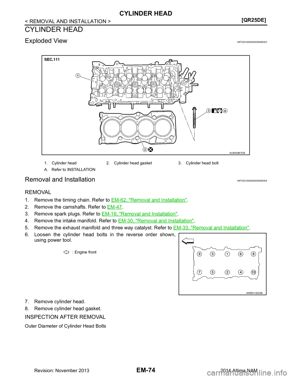
6. Loosen the cylinder head bolts in the reverse order shown, using power tool.
7. Remove cylinder head.
8. Remove cylinder head gasket.
INSPECTION AFTER REMOVAL
Outer Diameter of Cylinder Head Bolts
1. Cylinder head 2. Cylinder head gasket 3. Cylinder head bolt
A. Refer to INSTALLATION
ALBIA0867GB
: Engine front
AWBIA1325GB
Revision: November 20132014 Altima NAM
Page 2084 of 4801
EM-86
< UNIT REMOVAL AND INSTALLATION >[QR25DE]
ENGINE ASSEMBLY
NOTE:
If hydraulic pressure inside timing chain tensioner drops after removal and installation, slack in the guide
may generate a pounding noise during and just after engine start. However, this is normal. Noise will stop
after hydraulic pressure rises.
• Warm up engine thoroughly to make sure there is no leakage of fuel, exhaust gas, or any oils/fluids including engine oil and engine coolant.
• Bleed air from passages in lines and hoses, such as in cooling system.
• After cooling down engine, again check oil/fluid levels including engine oil and engine coolant. Refill to spec- ified level, if necessary.
• Summary of the inspection items:
*Power steering fluid, brake fluid, etc. Item Before starting engine Engine running After engine stopped
Engine coolant Level Leakage Level
Engine oil Level Leakage Level
Transmission/
transaxle fluid CVT Models
Leakage Level/Leakage Leakage
Other oils and fluids* Level Leakage Level
Fuel Leakage Leakage Leakage
Exhaust gas — Leakage —
Revision: November 20132014 Altima NAM
Page 2087 of 4801
CYLINDER BLOCKEM-89
< UNIT DISASSEMBLY AND ASSEMBLY > [QR25DE]
C
D E
F
G H
I
J
K L
M A
EM
NP
O
9. Remove the ignition coils. Refer to
EM-40, "Removal and Installation".
10. Remove the rocker cover. Refer to EM-45, "Removal and Installation"
.
11. Remove the front cover, timing chain, and balancer unit. Refer to EM-62, "Removal and Installation"
.
12. Remove the cylinder head. Refer to EM-74, "Removal and Installation"
.
13. Remove oil cooler. Refer to LU-16, "Exploded View"
.
14. Remove the knock sensor. CAUTION:
Carefully handle the sensor and do not drop the sensor.
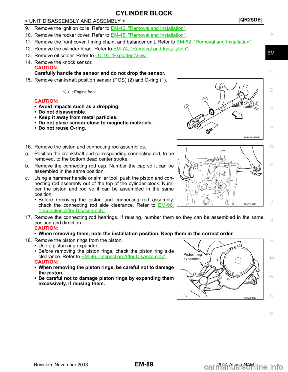
15. Remove crankshaft position sensor (POS) (2) and O-ring (1).
CAUTION:
• Avoid impacts such as a dropping.
• Do not disassemble.
• Keep it away from metal particles.
• Do not place sensor close to magnetic materials.
• Do not reuse O-ring.
16. Remove the piston and connecting rod assemblies.
a. Position the crankshaft and corresponding connecting rod, to be removed, to the bottom dead center stroke.
b. Remove the connecting rod cap. Number the cap so it can be assembled in the same position.
c. Using a hammer handle or similar tool, push the piston and con- necting rod assembly out of the top of the cylinder block. Num-
ber the piston and rod so it can be assembled in the same
position.
• Before removing the piston and connecting rod assembly,
check the connecting rod side clearance. Refer to EM-96,
"Inspection After Disassembly".
17. Remove the connecting rod bearings. If reusing, num ber them so they can be assembled in the same
position and direction.
CAUTION:
• When removing them, note the installation position. Keep them in the correct order.
18. Remove the piston rings from the piston. • Use a piston ring expander.
• Before removing the piston rings, check the piston ring side
clearance. Refer to EM-96, "Inspection After Disassembly"
.
CAUTION:
• When removing the piston rings, be careful not to damage
the piston.
• Be careful not to damage piston rings by expanding them excessively, if reusing them.
: Engine front
AWBIA1332GB
PBIC0259E
PBIC0087E
Revision: November 20132014 Altima NAM
Page 2125 of 4801
PREPARATIONEM-127
< PREPARATION > [VQ35DE]
C
D E
F
G H
I
J
K L
M A
EM
NP
O
Commercial Service ToolINFOID:0000000009460523
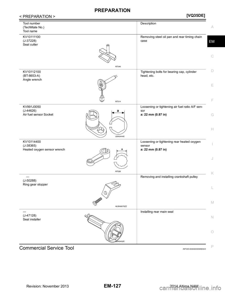
K V 1 0 1111 0 0
(J-37228)
Seal cutter Removing steel oil pan and rear timing chain
case
KV10112100
(BT-8653-A)
Angle wrench Tightening bolts for bearing cap, cylinder
head, etc.
KV991J0050
(J-44626)
Air fuel sensor Socket Loosening or tightening air fuel ratio A/F sen-
sor
a: 22 mm (0.87 in)
KV10114400
(J-38365)
Heated oxygen sensor wrench Loosening or tightening rear heated oxygen
sensor
a: 22 mm (0.87 in)
—
(J-50288)
Ring gear stopper Removing and installing crankshaft pulley
—
(J-47128)
Seal installer Installing rear main seal
Tool number
(TechMate No.)
Tool name Description
NT046
NT014
LBIA0444E
NT636
ALBIA0675ZZ
LBIA0452E
Revision: November 20132014 Altima NAM
Page 2129 of 4801
NOISE, VIBRATION, AND HARSHNESS (NVH) TROUBLESHOOTINGEM-131
< SYSTEM DESCRIPTION > [VQ35DE]
C
D E
F
G H
I
J
K L
M A
EM
NP
OUse the Chart Below to Help You
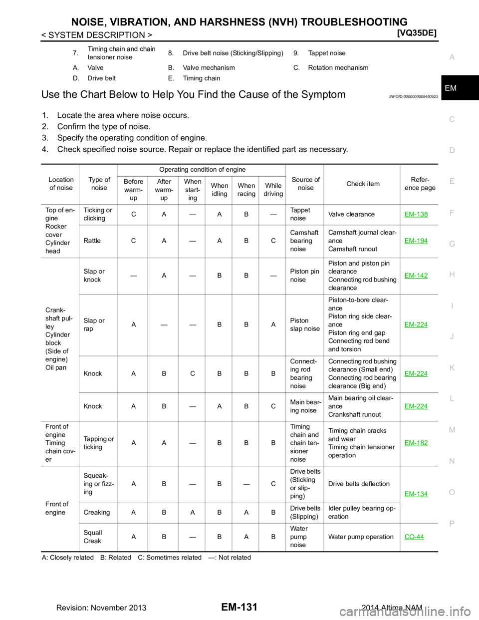
Find the Cause of the SymptomINFOID:0000000009460525
1. Locate the area where noise occurs.
2. Confirm the type of noise.
3. Specify the operating condition of engine.
4. Check specified noise source. Repair or replace the identified part as necessary.
A: Closely related B: Related C: Sometimes related —: Not related7.
Timing chain and chain
tensioner noise 8. Drive belt noise (Sticking/Slipping) 9. Tappet noise
A. Valve B. Valve mechanism C. Rotation mechanism
D. Drive belt E. Timing chain
Location of noise Type of
noise Operating condition of engine
Source of noise Check item Refer-
ence page
Before
warm- up After
warm- up When
start- ing When
idling When
racing While
driving
Top of en-
gine
Rocker
cover
Cylinder
head Ticking or
clicking CA—AB— Tappet
noise Valve clearance
EM-138
Rattle C A — A B C Camshaft
bearing
noise Camshaft journal clear-
ance
Camshaft runout EM-194
Crank-
shaft pul-
ley
Cylinder
block
(Side of
engine)
Oil pan Slap or
knock —A—BB— Piston pin
noise Piston and piston pin
clearance
Connecting rod bushing
clearance EM-142
Slap or
rap A——BBA Piston
slap noise Piston-to-bore clear-
ance
Piston ring side clear-
ance
Piston ring end gap
Connecting rod bend
and torsion EM-224
Knock A B C B B B
Connect-
ing rod
bearing
noise Connecting rod bushing
clearance (Small end)
Connecting rod bearing
clearance (Big end) EM-224
Knock A B — A B C
Main bear-
ing noise Main bearing oil clear-
ance
Crankshaft runout EM-224
Front of
engine
Timing
chain cov-
er Tapping or
ticking AA—BBB Timing
chain and
chain ten-
sioner
noise Timing chain cracks
and wear
Timing chain tensioner
operation EM-182
Front of
engine Squeak-
ing or fizz-
ing AB—B—C Drive belts
(Sticking
or slip-
ping) Drive belts deflection
EM-134
CreakingA B ABAB Drive belts
(Slipping) Idler pulley bearing op-
eration
Squall
Creak AB—BAB Water
pump
noise Water pump operation
CO-44
Revision: November 20132014 Altima NAM
Page 2159 of 4801
OIL PAN AND OIL STRAINEREM-161
< REMOVAL AND INSTALLATION > [VQ35DE]
C
D E
F
G H
I
J
K L
M A
EM
NP
O
• Run engine to check for unusual noise and vibration.
NOTE:
If hydraulic pressure inside timing chain tensioner dr ops after removal and installation, slack in the guide
may generate a pounding noise during and just after engine start. However, this is normal. Noise will stop
after hydraulic pressure rises.
• Warm up engine thoroughly to make sure there is no leak age of fuel, exhaust gas, or any oils/fluids including
engine oil and engine coolant.
• Bleed air from passages in lines and hoses, such as in cooling system.
• After cooling down engine, again check oil/fluid levels including engine oil and engine coolant. Refill to spec-
ified level, if necessary.
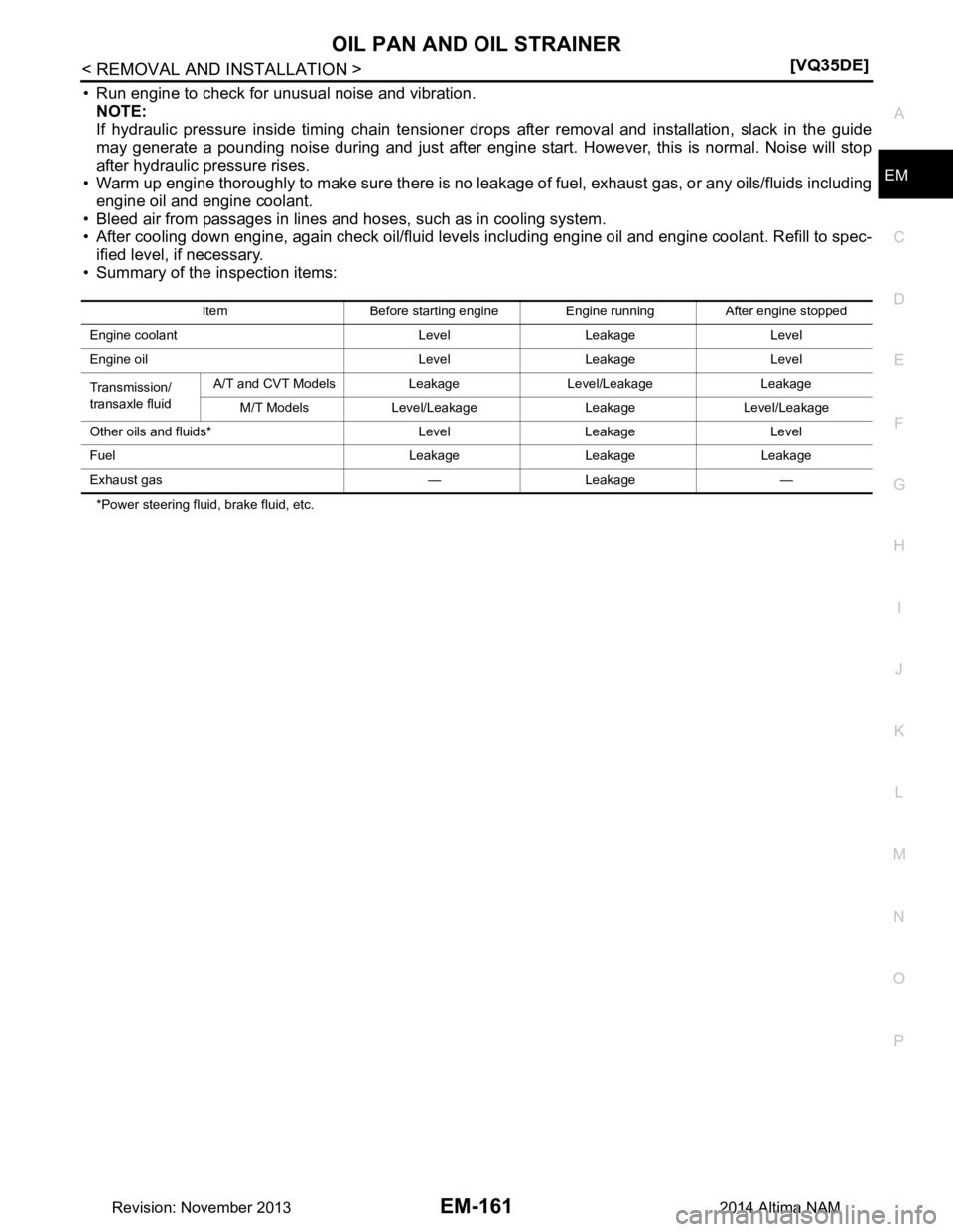
• Summary of the inspection items:
*Power steering fluid, brake fluid, etc. Item Before starting engine Engine running After engine stopped
Engine coolant Level Leakage Level
Engine oil Level Leakage Level
Transmission/
transaxle fluid A/T and CVT Models Leakage Level/Leakage Leakage
M/T Models Level/Leakage Leakage Level/Leakage
Other oils and fluids* Level Leakage Level
Fuel Leakage Leakage Leakage
Exhaust gas — Leakage —
Revision: November 20132014 Altima NAM
Page 2170 of 4801
EM-172
< REMOVAL AND INSTALLATION >[VQ35DE]
INTAKE VALVE TIMING CONTROL
INTAKE VALVE TIMING CONTROL
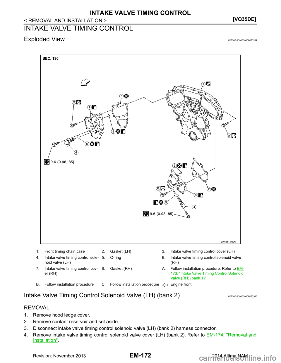
Exploded ViewINFOID:0000000009460559
Intake Valve Timing Control
Solenoid Valve (LH) (bank 2)INFOID:0000000009460560
REMOVAL
1. Remove hood ledge cover.
2. Remove coolant reservoir and set aside.
3. Disconnect intake valve timing control solenoid valve (LH) (bank 2) harness connector.
4. Remove intake valve timing control solenoid valve cover (LH) (bank 2). Refer to EM-174, "Removal and
Installation".
AWBIA1506ZZ
1. Front timing chain case 2. Gasket (LH) 3. Intake valve timing control cover (LH)
4. Intake valve timing control sole- noid valve (LH) 5. O-ring 6. Intake valve timing control solenoid valve
(RH)
7. Intake valve timing control cov- er (RH) 8. Gasket (RH) A. Follow installation procedure. Refer to
EM-
173, "Intake Valve Timing Control Solenoid
Valve (RH) (bank 1)"
B. Follow installation procedure C. Follow installation procedure Engine front
Revision: November 20132014 Altima NAM
Page 2171 of 4801
INTAKE VALVE TIMING CONTROLEM-173
< REMOVAL AND INSTALLATION > [VQ35DE]
C
D E
F
G H
I
J
K L
M A
EM
NP
O
5. Remove intake valve timing control solenoid valve (LH) (bank 2) and O-ring from intake valve timing con-
trol solenoid valve cover (LH) (bank 2).
CAUTION:
Do not reuse O-ring.
INSTALLATION
Installation is in the reverse order of removal.
CAUTION:
• Do not reuse O-ring.
• Replace the O-ring for the intake valve timing cont rol solenoid valve LH (bank 2) with a new one,
then lubricate O-ring with engine oil before installing.
Intake Valve Timing Control Solenoid Valve (RH) (bank 1)INFOID:0000000009460561
REMOVAL
1. Remove hood ledge cover.
2. Remove coolant reservoir and set aside.
3. Support engine using suitable tool.
4. Remove upper torque rod, engine mounting insulato r (RH), and engine mounting bracket (RH). Refer to
EM-220, "Removal and Installation"
.
5. Disconnect intake valve timing control solenoid valve (RH) (bank 1) harness connector.
6. Remove intake valve timing control solenoid valve ( RH) (bank 1) and O-ring from intake valve timing con-
trol solenoid valve cover (RH) (bank 1).
CAUTION:
Do not reuse O-ring.
INSTALLATION
Installation is in the reverse order of removal.
CAUTION:
• Do not reuse O-ring.
• Replace the O-ring for the intake valve timing contro l solenoid valve (RH) (bank 1) with a new one,
then lubricate O-ring with engine oil before installing.
Revision: November 20132014 Altima NAM