oil capacity NISSAN TEANA 2014 User Guide
[x] Cancel search | Manufacturer: NISSAN, Model Year: 2014, Model line: TEANA, Model: NISSAN TEANA 2014Pages: 4801, PDF Size: 51.2 MB
Page 3184 of 4801
![NISSAN TEANA 2014 User Guide
LU-34
< SERVICE DATA AND SPECIFICATIONS (SDS) [VQ35DE]
SERVICE DATA AND SPECIFICATIONS (SDS)
SERVICE DATA AND SPECIFICATIONS (SDS)
SERVICE DATA AND SPECIFICATIONS (SDS)
Oil PressureINFOID:00000000094](/img/5/57390/w960_57390-3183.png "NISSAN TEANA 2014 User Guide
LU-34
< SERVICE DATA AND SPECIFICATIONS (SDS) [VQ35DE]
SERVICE DATA AND SPECIFICATIONS (SDS)
SERVICE DATA AND SPECIFICATIONS (SDS)
SERVICE DATA AND SPECIFICATIONS (SDS)
Oil PressureINFOID:00000000094")
LU-34
< SERVICE DATA AND SPECIFICATIONS (SDS) [VQ35DE]
SERVICE DATA AND SPECIFICATIONS (SDS)
SERVICE DATA AND SPECIFICATIONS (SDS)
SERVICE DATA AND SPECIFICATIONS (SDS)
Oil PressureINFOID:0000000009461057
Unit: kPa (kg/cm2, psi)
*: Engine oil temperature at 80
°C (176 °F)
Oil PumpINFOID:0000000009461058
Unit: mm (in)
Regulator ValveINFOID:0000000009461059
Unit: mm (in)
Oil CapacityINFOID:0000000009461060
Unit: (US qt, Imp qt)
Engine speed Approximate discharge oil pressure*
Idle speed 98 (1.0, 14)
2,000 rpm 294 (3.0, 43)
6,000 rpm 392 (4.0, 57)
Clearance between outer rotor and oil pump body 0.114 - 0.260 (0.0045 - 0.0102)
Tip clearance between inner rotor and outer rotor Below 0.180 (0.0071)
Side clearance between inner rotor and oil pump body 0.030 - 0.070 (0.0012 - 0.0028)
Side clearance between outer rotor and oil pump body 0.050 - 0.110 (0.0020 - 0.0043)
Clearance between inner rotor and oil pump body 0.045 - 0.091 (0.0018 - 0.0036)
Regulator valve to oil pump cover clearance 0.040 - 0.097 (0.0016 - 0.0038)
Drain and refill With oil filter change 4.8 (5-1/8, 4-1/4)
Without oil filter change 4.5 (4-3/4, 4)
Dry engine (engine overhaul) 5.3 (5-5/8, 4-5/8)
Revision: November 20132014 Altima NAM
Page 3195 of 4801
RECOMMENDED FLUIDS AND LUBRICANTSMA-11
< PERIODIC MAINTENANCE >
C
D E
F
G H
I
J
K L
M B
MA
N
O A
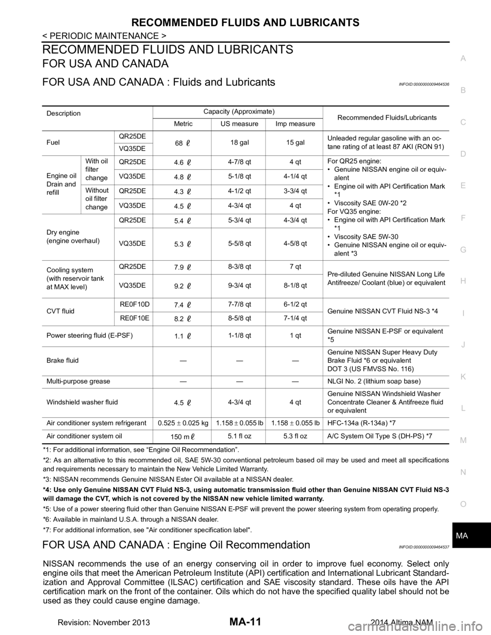
RECOMMENDED FLUIDS AND LUBRICANTS
FOR USA AND CANADA
FOR USA AND CANADA :
Fluids and LubricantsINFOID:0000000009464536
*1: For additional information, see “Engine Oil Recommendation”.
*2: As an alternative to this recommended oil, SAE 5W-30 conventional petroleum based oil may be used and meet all specificatio ns
and requirements necessary to maintain the New Vehicle Limited Warranty.
*3: NISSAN recommen ds Genuine NISSAN Ester Oil av ailable at a NISSAN dealer.
*4: Use only Genuine NISSAN CVT Fluid NS -3, using automatic transmission fluid other than Genuine NISSAN CVT Fluid NS-3
will damage the CVT, which is not covered by the NISSAN new vehicle limited warranty.
*5: Use of a power steering fluid other than Genuine NISSAN E-PSF will prevent the power steering system from operating properly.
*6: Available in mainland U. S.A. through a NISSAN dealer.
*7: For additional information, see "Air conditioner specification label".
FOR USA AND CANADA : En gine Oil RecommendationINFOID:0000000009464537
NISSAN recommends the use of an energy conserving o il in order to improve fuel economy. Select only
engine oils that meet the American Petroleum Institut e (API) certification and International Lubricant Standard-
ization and Approval Committee (ILSAC) certificati on and SAE viscosity standard. These oils have the API
certification mark on the front of the container. Oils which do not have the specified quality label should not be
used as they could cause engine damage.
Description Capacity (Approximate)
Recommended Fluids/Lubricants
Metric US measure Imp measure
Fuel QR25DE
68 18 gal 15 gal Unleaded regular gasoline with an oc-
tane rating of at least 87 AKI (RON 91)
VQ35DE
Engine oil
Drain and
refill With oil
filter
change QR25DE
4.6 4-7/8 qt 4 qt For QR25 engine:
• Genuine NISSAN engine oil or equiv- alent
• Engine oil with API Certification Mark
*1
• Viscosity SAE 0W-20 *2
For VQ35 engine:
• Engine oil with API Certification Mark
*1
• Viscosity SAE 5W-30
• Genuine NISSAN engine oil or equiv-
alent *3
VQ35DE
4.8 5-1/8 qt 4-1/4 qt
Without
oil filter
change QR25DE
4.3 4-1/2 qt 3-3/4 qt
VQ35DE 4.5 4-3/4 qt 4 qt
Dry engine
(engine overhaul) QR25DE
5.4 5-3/4 qt 4-3/4 qt
VQ35DE 5.3 5-5/8 qt 4-5/8 qt
Cooling system
(with reservoir tank
at MAX level) QR25DE
7.9 8-3/8 qt 7 qt
Pre-diluted Genuine NISSAN Long Life
Antifreeze/ Coolant (blue) or equivalent
VQ35DE 9.2 9-3/4 qt 8-1/8 qt
CVT fluid RE0F10D
7.4 7-7/8 qt 6-1/2 qt
Genuine NISSAN CVT Fluid NS-3 *4
RE0F10E 8.2 8-5/8 qt 7-1/4 qt
Power steering fluid (E-PSF) 1.1 1-1/8 qt 1 qt Genuine NISSAN E-PSF or equivalent
*5
Brake fluid — — — Genuine NISSAN Super Heavy Duty
Brake Fluid *6 or equivalent
DOT 3 (US FMVSS No. 116)
Multi-purpose grease — — — NLGI No. 2 (lithium soap base)
Windshield washer fluid 4.5 4-3/4 qt 4 qt Genuine NISSAN Windshield Washer
Concentrate Cleaner & Antifreeze fluid
or equivalent
Air conditioner system refrigerant 0.525 ± 0.025 kg 1.158 ± 0.055 lb 1.158 ± 0.055 lb HFC-134a (R-134a) *7
Air conditioner system oil 150 m5.1 fl oz 5.3 fl oz A/C System Oil Type S (DH-PS) *7
Revision: November 20132014 Altima NAM
Page 3202 of 4801
MA-18
< PERIODIC MAINTENANCE >
ENGINE MAINTENANCE (QR25DE)
• Prolonged and repeated contact with used engine oil may cause skin cancer: try to avoid direct skin
contact with used oil. If skin contact is made, wash thoroughly with soap or hand cleaner as soon as
possible.
1. Position the vehicle so it is level on the hoist.
2. Warm up the engine and check for oil leaks from the engine.
3. Stop engine and wait for 10 minutes.
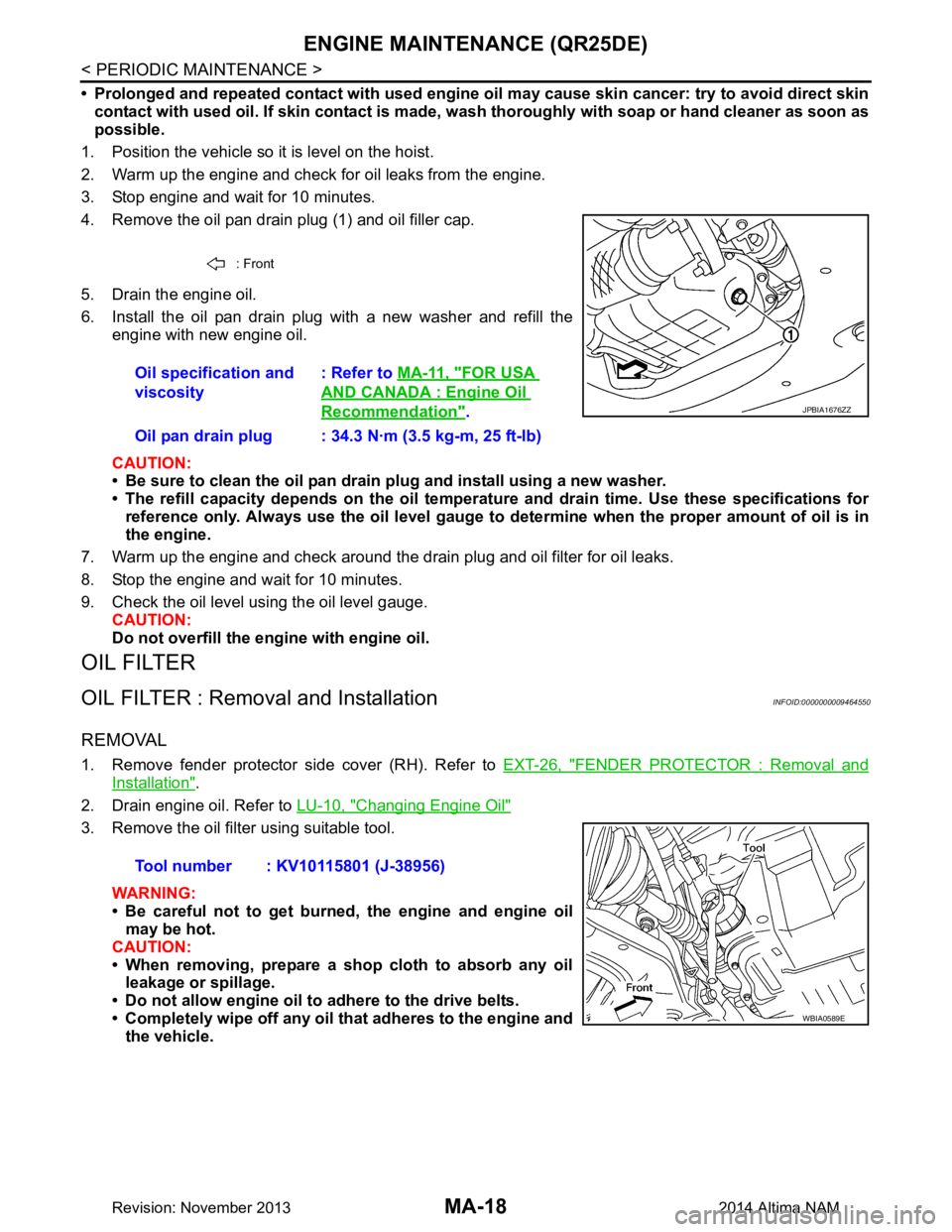
4. Remove the oil pan drain plug (1) and oil filler cap.
5. Drain the engine oil.
6. Install the oil pan drain plug with a new washer and refill the engine with new engine oil.
CAUTION:
• Be sure to clean the oil pan drain plug and install using a new washer.
• The refill capacity depends on the oil temper ature and drain time. Use these specifications for
reference only. Always use the oil level gauge to determine when the proper amount of oil is in
the engine.
7. Warm up the engine and check around the drain plug and oil filter for oil leaks.
8. Stop the engine and wait for 10 minutes.
9. Check the oil level using the oil level gauge. CAUTION:
Do not overfill the engine with engine oil.
OIL FILTER
OIL FILTER : Removal and InstallationINFOID:0000000009464550
REMOVAL
1. Remove fender protector side cover (RH). Refer to EXT-26, "FENDER PROTECTOR : Removal and
Installation".
2. Drain engine oil. Refer to LU-10, "Changing Engine Oil"
3. Remove the oil filter using suitable tool.
WARNING:
• Be careful not to get burned, the engine and engine oil may be hot.
CAUTION:
• When removing, prepare a shop cloth to absorb any oil leakage or spillage.
• Do not allow engine oil to adhere to the drive belts.
• Completely wipe off any oil that adheres to the engine and
the vehicle.
: Front
Oil specification and
viscosity : Refer to
MA-11, "FOR USA
AND CANADA : Engine Oil
Recommendation".
Oil pan drain plug : 34.3 N·m (3.5 kg-m, 25 ft-lb)JPBIA1676ZZ
Tool number : KV10115801 (J-38956)
WBIA0589E
Revision: November 20132014 Altima NAM
Page 3208 of 4801
MA-24
< PERIODIC MAINTENANCE >
ENGINE MAINTENANCE (VQ35DE)
REFILLING ENGINE COOLANT
1. Install the radiator drain plug. If the cooling system was drained completely, install the reservoir tank and
the cylinder block drain plugs.
• The radiator must be complete ly empty of coolant and water.
• Apply sealant to the threads of the cylinder block drain plug. Use Genuine High Performance
Thread Sealant or equivalent. Refer to GI-21, "Recommended Chemical Products and Sealants"
.
CAUTION:
Do not reuse copp er sealing washers.
2. If disconnected, reattach the upper radiator hose at the engine side.
3. Set the vehicle heater controls to the full HOT and heat er ON position. Turn the vehicle ignition ON with
the engine OFF as necessary to activate the heater mode.
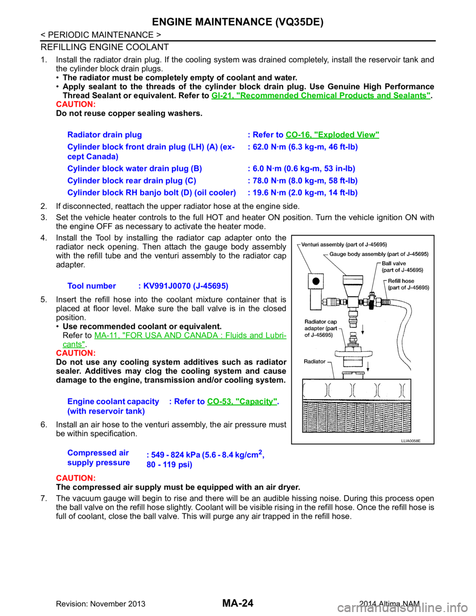
4. Install the Tool by installing the radiator cap adapter onto the radiator neck opening. Then attach the gauge body assembly
with the refill tube and the venturi assembly to the radiator cap
adapter.
5. Insert the refill hose into the coolant mixture container that is placed at floor level. Make sure the ball valve is in the closed
position.
• Use recommended coolant or equivalent.
Refer to MA-11, "FOR USA AND CANADA : Fluids and Lubri-
cants".
CAUTION:
Do not use any cooling system additives such as radiator
sealer. Additives may clog th e cooling system and cause
damage to the engine, transm ission and/or cooling system.
6. Install an air hose to the venturi assembly, the air pressure must be within specification.
CAUTION:
The compressed air supply must be equipped with an air dryer.
7. The vacuum gauge will begin to rise and there will be an audible hissing noise. During this process open the ball valve on the refill hose slightly. Coolant will be vi sible rising in the refill hose. Once the refill hose is
full of coolant, close the ball valve. This will purge any air trapped in the refill hose. Radiator drain plug : Refer to
CO-16, "Exploded View"
Cylinder block front drain plug (LH) (A) (ex-
cept Canada) : 62.0 N·m (6.3 kg-m, 46 ft-lb)
Cylinder block water drain plug (B) : 6.0 N·m (0.6 kg-m, 53 in-lb)
Cylinder block rear drain plug (C) : 78.0 N·m (8.0 kg-m, 58 ft-lb)
Cylinder block RH banjo bolt (D) (oil cooler) : 19.6 N·m (2.0 kg-m, 14 ft-lb)
Tool number : KV991J0070 (J-45695)
Engine coolant capacity
(with reservoir tank) : Refer to
CO-53, "Capacity"
.
Compressed air
supply pressure : 549 - 824 kPa (5.6 - 8.4 kg/cm
2,
80 - 119 psi)
LLIA0058E
Revision: November 20132014 Altima NAM
Page 3211 of 4801
ENGINE MAINTENANCE (VQ35DE)MA-27
< PERIODIC MAINTENANCE >
C
D E
F
G H
I
J
K L
M B
MA
N
O A
• Before starting the engine, check the oil level. If the engine is
already started, stop it and a llow 10 minutes before checking.
• Check that the oil level is within the range as indicated on the oil
level gauge.
• If it is out of range, add oil as necessary.
ENGINE OIL : Changing Engine OilINFOID:0000000009464560
WARNING:
• Be careful not to burn yourself, as the engine oil may be hot.
• Prolonged and repeated contact with used engine oil may cau se skin cancer; try to avoid direct skin
contact with used oil. If skin contact is made, w ash thoroughly with soap or hand cleaner as soon as
possible.
1. Position the vehicle so it is level on the hoist.
2. Warm up the engine and check for oil leaks from the engine.
3. Stop engine and wait for 10 minutes.
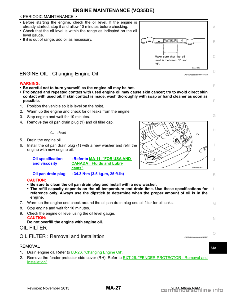
4. Remove the oil pan drain plug (1) and oil filler cap.
5. Drain the engine oil.
6. Install the oil pan drain plug (1) with a new washer and refill the engine with new engine oil.
CAUTION:
• Be sure to clean the oil pan drain plug and install with a new washer.
• The refill capacity depends on the oil temper ature and drain time. Use these specifications for
reference only. Always use the dipstick to determin e when the proper amount of oil is in the
engine.
7. Warm up the engine and check around the oil pan drain plug and oil filter for oil leaks.
8. Stop engine and wait for 10 minutes.
9. Check the engine oil level using the oil level gauge. CAUTION:
Do not overfill the en gine with engine oil.
OIL FILTER
OIL FILTER : Removal and InstallationINFOID:0000000009464561
REMOVAL
1. Drain engine oil. Refer to LU-26, "Changing Engine Oil".
2. Remove the fender protector side cover (RH). Refer to EXT-26, "FENDER PROTECTOR : Removal and
Installation".
JMA122D
: Front
Oil specification
and viscosity : Refer to
MA-11, "FOR USA AND
CANADA : Fluids and Lubri-
cants".
Oil pan drain plug : 34.3 N·m (3.5 kg-m, 25 ft-lb)JPBIA1676ZZ
Revision: November 20132014 Altima NAM
Page 3216 of 4801
MA-32
< PERIODIC MAINTENANCE >
CHASSIS AND BODY MAINTENANCE
CVT FLUID : RE0F10D
INFOID:0000000009464566
CVT FLUID : InspectionINFOID:0000000009464567
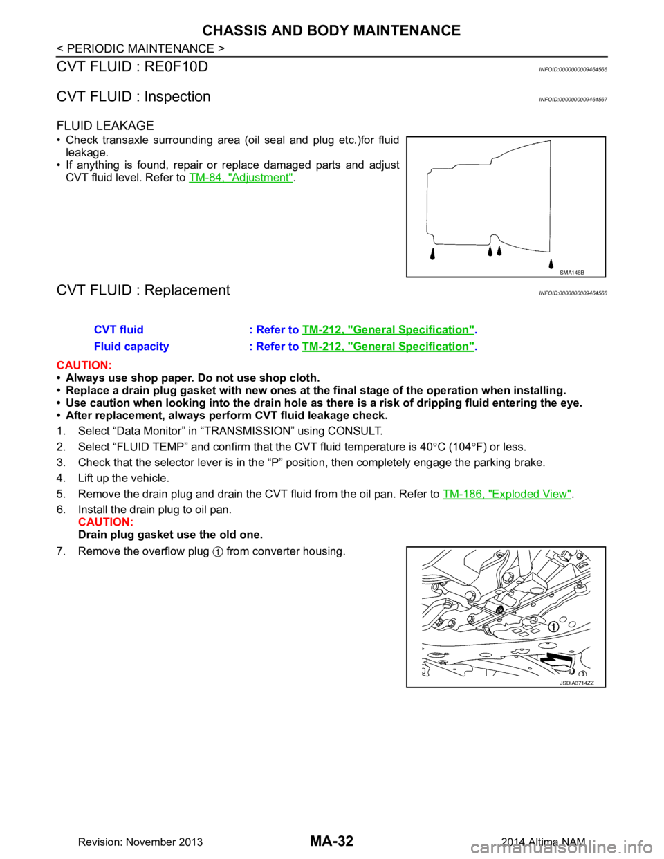
FLUID LEAKAGE
• Check transaxle surrounding area (oil seal and plug etc.)for fluid leakage.
• If anything is found, repair or replace damaged parts and adjust CVT fluid level. Refer to TM-84, "Adjustment"
.
CVT FLUID : ReplacementINFOID:0000000009464568
CAUTION:
• Always use shop paper. Do not use shop cloth.
• Replace a drain plug gasket with new ones at the final stage of the operation when installing.
• Use caution when looking into the drain hole as th ere is a risk of dripping fluid entering the eye.
• After replacement, always perform CVT fluid leakage check.
1. Select “Data Monitor” in “T RANSMISSION” using CONSULT.
2. Select “FLUID TEMP” and confirm t hat the CVT fluid temperature is 40°C (104 °F) or less.
3. Check that the selector lever is in the “P ” position, then completely engage the parking brake.
4. Lift up the vehicle.
5. Remove the drain plug and drain the CVT fluid from the oil pan. Refer to TM-186, "Exploded View"
.
6. Install the drain plug to oil pan. CAUTION:
Drain plug gasket use the old one.
7. Remove the overflow plug from converter housing.
SMA146B
CVT fluid : Refer to TM-212, "General Specification".
Fluid capacity : Refer to TM-212, "General Specification"
.
JSDIA3714ZZ
Revision: November 20132014 Altima NAM
Page 3218 of 4801
MA-34
< PERIODIC MAINTENANCE >
CHASSIS AND BODY MAINTENANCE
34. Select “Data Monitor” in “TRANSMISSION” using CONSULT.
35. Select “CONFORM CVTF DETERIORTN”.
36. Select “Erase”.
37. Stop the engine.
CVT FLUID : AdjustmentINFOID:0000000009464569
CAUTION:
• During adjustment of the CVT fluid level, check CO NSULT so that the oil temperature may be main-
tained from 35 to 45 °C (95 to 113 °F).
• During adjustment of the CVT fluid level, check that the engine speed is maintaining 500 rpm.
• Use caution when looking into the drain hole as th ere is a risk of dripping fluid entering the eye.
1. Check that the selector lever is in the “P ” position, then completely engage the parking brake.
2. Start the engine.
3. Adjust the CVT fluid temperature to be approximately 40 °C (104 °F).
NOTE:
The CVT fluid is largely affected by temperature. Therefore be sure to use CONSULT and check the
“FLUID TEMP” under “TRANSMISSION” in “Data Monitor” while adjusting.
4. While depressing the brake pedal, shift the selector lever to the entire position from “P” to “DS”, and shift it to the “P” position.
NOTE:
Hold the lever at each position for 5 seconds.
5. Lift up the vehicle.
6. Check that there is no CVT fluid leakage.
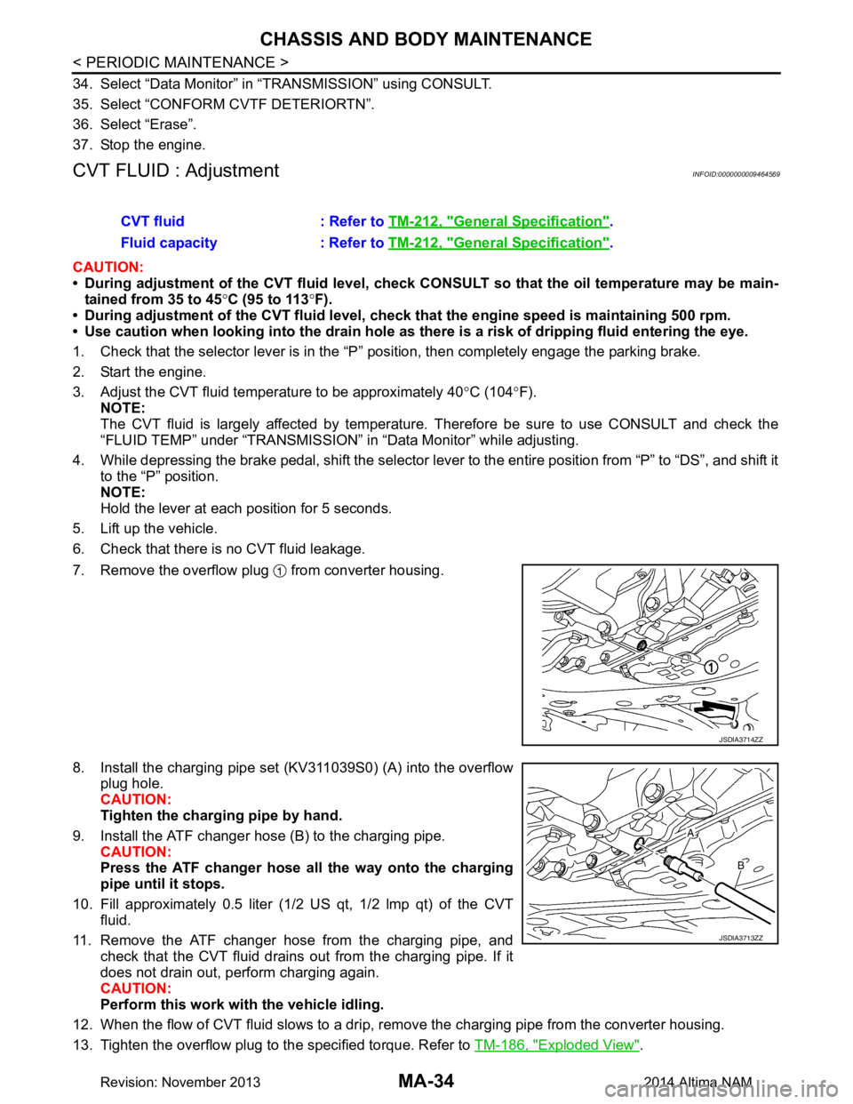
7. Remove the overflow plug from converter housing.
8. Install the charging pipe set (KV311039S0) (A) into the overflow plug hole.
CAUTION:
Tighten the charging pipe by hand.
9. Install the ATF changer hose (B) to the charging pipe. CAUTION:
Press the ATF changer hose all the way onto the charging
pipe until it stops.
10. Fill approximately 0.5 liter (1/2 US qt, 1/2 lmp qt) of the CVT
fluid.
11. Remove the ATF changer hose from the charging pipe, and check that the CVT fluid drains out from the charging pipe. If it
does not drain out, perform charging again.
CAUTION:
Perform this work with the vehicle idling.
12. When the flow of CVT fluid slows to a drip, re move the charging pipe from the converter housing.
13. Tighten the overflow plug to the specified torque. Refer to TM-186, "Exploded View"
.
CVT fluid : Refer to
TM-212, "General Specification"
.
Fluid capacity : Refer to TM-212, "General Specification"
.
JSDIA3714ZZ
JSDIA3713ZZ
Revision: November 20132014 Altima NAM
Page 3219 of 4801
CHASSIS AND BODY MAINTENANCEMA-35
< PERIODIC MAINTENANCE >
C
D E
F
G H
I
J
K L
M B
MA
N
O A
CAUTION:
Do not reuse O-ring.
14. Lift down the vehicle.
15. Stop the engine.
CVT FLUID : RE0F10EINFOID:0000000009464570
CVT FLUID : InspectionINFOID:0000000009464571
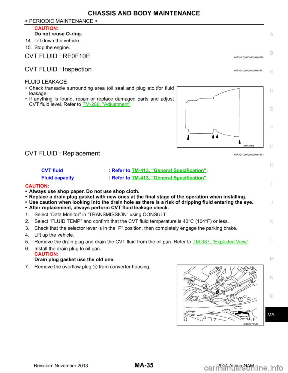
FLUID LEAKAGE
• Check transaxle surrounding area (oil seal and plug etc.)for fluid leakage.
• If anything is found, repair or replace damaged parts and adjust
CVT fluid level. Refer to TM-286, "Adjustment"
.
CVT FLUID : ReplacementINFOID:0000000009464572
CAUTION:
• Always use shop paper. Do not use shop cloth.
• Replace a drain plug gasket with new ones at the fi nal stage of the operation when installing.
• Use caution when looking into the drain hole as there is a risk of dripping fluid entering the eye.
• After replacement, always pe rform CVT fluid leakage check.
1. Select “Data Monitor” in “TRANSMISSION” using CONSULT.
2. Select “FLUID TEMP” and confirm t hat the CVT fluid temperature is 40°C (104 °F) or less.
3. Check that the selector lever is in the “P ” position, then completely engage the parking brake.
4. Lift up the vehicle.
5. Remove the drain plug and drain the CVT fluid from the oil pan. Refer to TM-387, "Exploded View"
.
6. Install the drain plug to oil pan. CAUTION:
Drain plug gasket use the old one.
7. Remove the overflow plug from converter housing.
SMA146B
CVT fluid : Refer to TM-413, "General Specification".
Fluid capacity : Refer to TM-413, "General Specification"
.
JSDIA3714ZZ
Revision: November 20132014 Altima NAM
Page 3221 of 4801
CHASSIS AND BODY MAINTENANCEMA-37
< PERIODIC MAINTENANCE >
C
D E
F
G H
I
J
K L
M B
MA
N
O A
34. Select “Data Monitor” in “TRANSMISSION” using CONSULT.
35. Select “CONFORM CVTF DETERIORTN”.
36. Select “Erase”.
37. Stop the engine.
CVT FLUID : AdjustmentINFOID:0000000009464573
CAUTION:
• During adjustment of the CVT fluid level, check CO NSULT so that the oil temperature may be main-
tained from 35 to 45 °C (95 to 113 °F).
• During adjustment of the CVT fluid level, check that the engine speed is maintaining 500 rpm.
• Use caution when looking into the drain hole as there is a risk of dripping fluid entering the eye.
1. Check that the selector lever is in the “P ” position, then completely engage the parking brake.
2. Start the engine.
3. Adjust the CVT fluid temperature to be approximately 40 °C (104 °F).
NOTE:
The CVT fluid is largely affected by temperature. Therefore be sure to use CONSULT and check the
“FLUID TEMP” under “TRA NSMISSION” in “Data Monitor” while adjusting.
4. While depressing the brake pedal, shift the selector leve r to the entire position from “P” to “DS”, and shift it
to the “P” position.
NOTE:
Hold the lever at each position for 5 seconds.
5. Lift up the vehicle.
6. Check that there is no CVT fluid leakage.
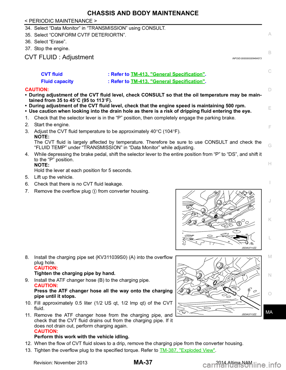
7. Remove the overflow plug from converter housing.
8. Install the charging pipe set (KV311039S0) (A) into the overflow plug hole.
CAUTION:
Tighten the charging pipe by hand.
9. Install the ATF changer hose (B) to the charging pipe. CAUTION:
Press the ATF changer hose all the way onto the charging
pipe until it stops.
10. Fill approximately 0.5 liter (1/2 US qt, 1/2 lmp qt) of the CVT
fluid.
11. Remove the ATF changer hose from the charging pipe, and check that the CVT fluid drains out from the charging pipe. If it
does not drain out, perform charging again.
CAUTION:
Perform this work with the vehicle idling.
12. When the flow of CVT fluid slows to a drip, re move the charging pipe from the converter housing.
13. Tighten the overflow plug to the specified torque. Refer to TM-387, "Exploded View"
.
CVT fluid : Refer to
TM-413, "General Specification"
.
Fluid capacity : Refer to TM-413, "General Specification"
.
JSDIA3714ZZ
JSDIA3713ZZ
Revision: November 20132014 Altima NAM
Page 4151 of 4801

ST-48
< SERVICE DATA AND SPECIFICATIONS (SDS)
SERVICE DATA AND SPECIFICATIONS (SDS)
RACK SLIDING FORCE
Power Steering Oil PumpINFOID:0000000009461285
Power Steering FluidINFOID:0000000009461286
P215/60R16 P215/55R17 - P245/45R18
Rack stroke in neutral position (L) 72.5 mm (2.9in) 70.0 mm (2.8in)
Average 330 N (33.7 kg, 74.2 lb)
Relief oil pressure
9,700 - 10,300 kPa (98.9 - 105.1 kg/cm2, 1406.5 - 1493.5 psi)
Fluid type E-PSF
Fluid capacity 1.1 (1-1/8 US qt, 1 lmp qt)
Revision: November 20132014 Altima NAMRevision: November 20132014 Altima NAM