timing NISSAN TEANA 2014 Manual PDF
[x] Cancel search | Manufacturer: NISSAN, Model Year: 2014, Model line: TEANA, Model: NISSAN TEANA 2014Pages: 4801, PDF Size: 51.2 MB
Page 1386 of 4801
EC-386
< DTC/CIRCUIT DIAGNOSIS >[QR25DE]
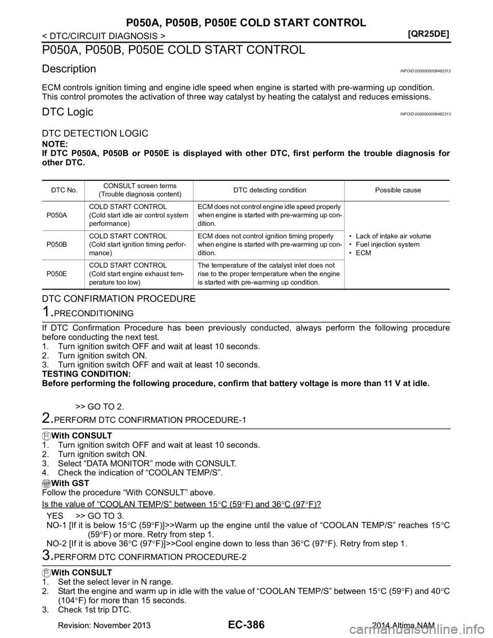
P050A, P050B, P050E COLD START CONTROL
P050A, P050B, P050E COLD START CONTROL
DescriptionINFOID:0000000009462312
ECM controls ignition timing and engine idle speed when engine is started with pre-warming up condition.
This control promotes the activation of three way ca talyst by heating the catalyst and reduces emissions.
DTC LogicINFOID:0000000009462313
DTC DETECTION LOGIC
NOTE:
If DTC P050A, P050B or P050E is displayed with ot her DTC, first perform the trouble diagnosis for
other DTC.
DTC CONFIRMATION PROCEDURE
1.PRECONDITIONING
If DTC Confirmation Procedure has been previously conducted, always perform the following procedure
before conducting the next test.
1. Turn ignition switch OFF and wait at least 10 seconds.
2. Turn ignition switch ON.
3. Turn ignition switch OFF and wait at least 10 seconds.
TESTING CONDITION:
Before performing the following procedure, confirm that battery voltage is more than 11 V at idle.
>> GO TO 2.
2.PERFORM DTC CONFIRMATION PROCEDURE-1
With CONSULT
1. Turn ignition switch OFF and wait at least 10 seconds.
2. Turn ignition switch ON.
3. Select “DATA MONITOR” mode with CONSULT.
4. Check the indication of “COOLAN TEMP/S”.
With GST
Follow the procedure “With CONSULT” above.
Is the value of
“COOLAN TEMP/S” between 15°C (59°F) and 36°C (97°F)?
YES >> GO TO 3.
NO-1 [If it is below 15 °C (59 °F)]>>Warm up the engine until the value of “COOLAN TEMP/S” reaches 15 °C
(59 °F) or more. Retry from step 1.
NO-2 [If it is above 36 °C (97 °F)]>>Cool engine down to less than 36 °C (97 °F). Retry from step 1.
3.PERFORM DTC CONFIRMATION PROCEDURE-2
With CONSULT
1. Set the select lever in N range.
2. Start the engine and warm up in idle with the value of “COOLAN TEMP/S” between 15 °C (59 °F) and 40 °C
(104 °F) for more than 15 seconds.
3. Check 1st trip DTC.
DTC No. CONSULT screen terms
(Trouble diagnosis content) DTC detecting condition Possible cause
P050A COLD START CONTROL
(Cold start idle air control system
performance) ECM does not control engine idle speed properly
when engine is started with pre-warming up con-
dition.
• Lack of intake air volume
• Fuel injection system
•ECM
P050B
COLD START CONTROL
(Cold start ignition timing perfor-
mance) ECM does not control ignition timing properly
when engine is started with pre-warming up con-
dition.
P050E COLD START CONTROL
(Cold start engine exhaust tem-
perature too low) The temperature of the catalyst inlet does not
rise to the proper temperature when the engine
is started with pre-warming up condition.
Revision: November 20132014 Altima NAMRevision: November 20132014 Altima NAM
Page 1394 of 4801
EC-394
< DTC/CIRCUIT DIAGNOSIS >[QR25DE]
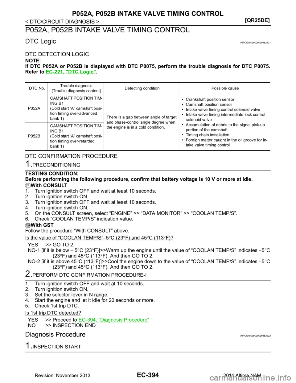
P052A, P052B INTAKE VALVE TIMING CONTROL
P052A, P052B INTAKE VALVE TIMING CONTROL
DTC LogicINFOID:0000000009462321
DTC DETECTION LOGIC
NOTE:
If DTC P052A or P052B is displayed with DTC P 0075, perform the trouble diagnosis for DTC P0075.
Refer to EC-221, "DTC Logic"
.
DTC CONFIRMATION PROCEDURE
1.PRECONDITIONING
TESTING CONDITION:
Before performing the following procedure, confi rm that battery voltage is 10 V or more at idle.
With CONSULT
1. Turn ignition switch OFF and wait at least 10 seconds.
2. Turn ignition switch ON.
3. Turn ignition switch OFF and wait at least 10 seconds.
4. Turn ignition switch ON.
5. On the CONSULT screen, select “ENGINE” >> “DATA MONITOR” >> “COOLAN TEMP/S”.
6. Check “COOLAN TEMP/S” indication value.
With GST
Follow the procedure “With CONSULT” above.
Is the value of
“COOLAN TEMP/S”−5°C (23°F) and 45°C (11 3°F)?
YES >> GO TO 2.
NO-1 [if it is below − 5 °C (23 °F)]>>Warm up the engine until the value of “COOLAN TEMP/S” indicates −5 °C
(23 °F) and 45 °C (113 °F). And then GO TO 2.
NO-2 [if it is above 45 °C (113 °F)]>>Cool the engine down to the val ue of “COOLAN TEMP/S” indicates −5 °C
(23 °F) and 45 °C (113 °F). And then GO TO 2.
2.PERFORM DTC CONFIRMATION PROCEDURE-I
1. Turn ignition switch OFF and wait at 10 seconds.
2. Turn ignition switch ON.
3. Set the selector lever in N range.
4. Start the engine and let it idle for 20 seconds or more.
5. Check 1st trip DTC.
Is 1st trip DTC detected?
YES >> Proceed to EC-394, "Diagnosis Procedure"
NO >> INSPECTION END
Diagnosis ProcedureINFOID:0000000009462322
1.INSPECTION START
DTC No.Trouble diagnosis
(Trouble diagnosis content) Detecting condition Possible cause
P052A CAMSHAFT POSITION TIM-
ING B1
(Cold start “A” camshaft posi-
tion timing over-advanced
bank 1) There is a gap between angle of target
and phase-control angle degree when
the engine is in a cold condition. • Crankshaft position sensor
• Camshaft position sensor
• Intake valve timing control solenoid valve
• Intake valve timing intermediate lock control solenoid valve
• Accumulation of debris to the signal pick-up portion of the camshaft
• Timing chain installation
• Foreign matter caught in the oil groove for in- take valve timing control
P052B CAMSHAFT POSITION TIM-
ING B1
(Cold start “A” camshaft posi-
tion timing over-retarded
bank 1)
Revision: November 20132014 Altima NAMRevision: November 20132014 Altima NAM
Page 1395 of 4801
P052A, P052B INTAKE VALVE TIMING CONTROLEC-395
< DTC/CIRCUIT DIAGNOSIS > [QR25DE]
C
D E
F
G H
I
J
K L
M A
EC
NP
O
With CONSULT>>GO TO 2.
Without CONSULT>>GO TO 3.
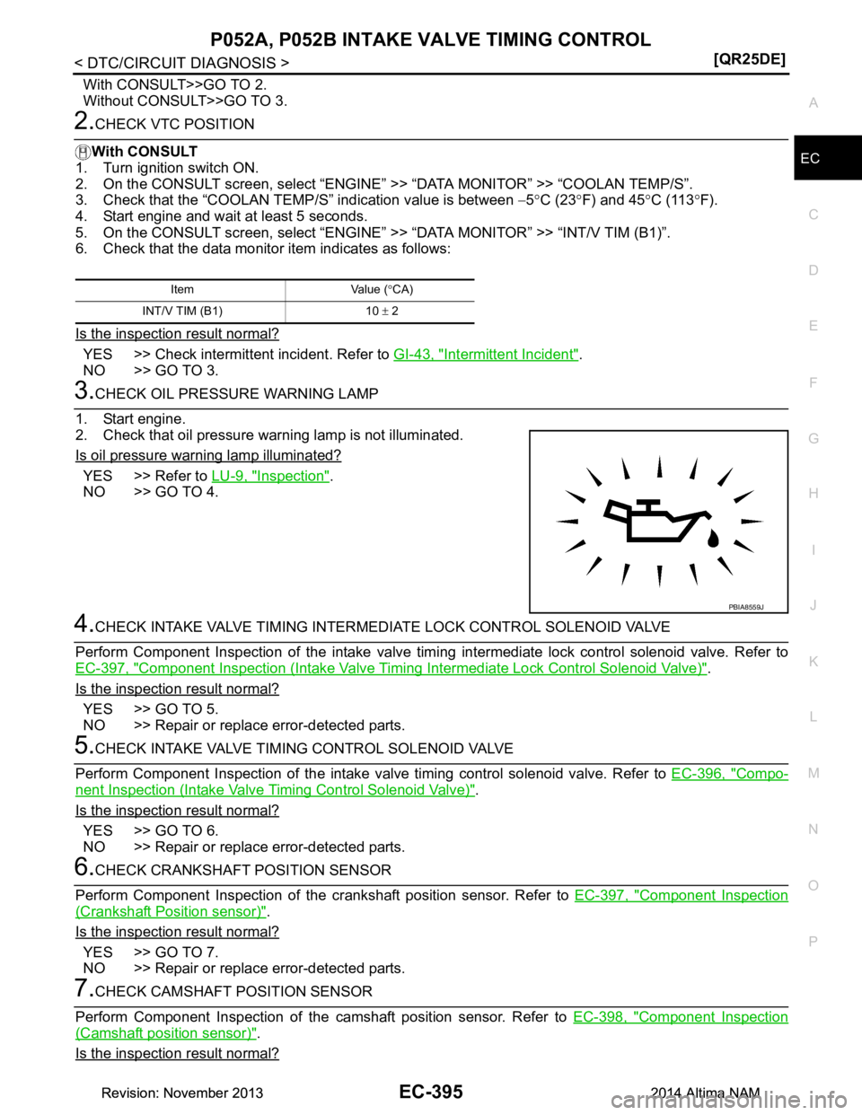
2.CHECK VTC POSITION
With CONSULT
1. Turn ignition switch ON.
2. On the CONSULT screen, select “ENGINE” >> “DATA MONITOR” >> “COOLAN TEMP/S”.
3. Check that the “COOLAN TEMP/S” indication value is between −5 °C (23 °F) and 45 °C (113 °F).
4. Start engine and wait at least 5 seconds.
5. On the CONSULT screen, select “ENGINE” >> “DATA MONITOR” >> “INT/V TIM (B1)”.
6. Check that the data monitor item indicates as follows:
Is the inspection result normal?
YES >> Check intermittent incident. Refer to GI-43, "Intermittent Incident".
NO >> GO TO 3.
3.CHECK OIL PRESSURE WARNING LAMP
1. Start engine.
2. Check that oil pressure warning lamp is not illuminated.
Is oil pressure warning lamp illuminated?
YES >> Refer to LU-9, "Inspection".
NO >> GO TO 4.
4.CHECK INTAKE VALVE TIMING INTERMEDIA TE LOCK CONTROL SOLENOID VALVE
Perform Component Inspection of the intake valve timi ng intermediate lock control solenoid valve. Refer to
EC-397, "Component Inspection (Intake Valve Timing Intermediate Lock Control Solenoid Valve)"
.
Is the inspection result normal?
YES >> GO TO 5.
NO >> Repair or replace error-detected parts.
5.CHECK INTAKE VALVE TIMING CONTROL SOLENOID VALVE
Perform Component Inspection of the intake va lve timing control solenoid valve. Refer to EC-396, "Compo-
nent Inspection (Intake Valve Timing Control Solenoid Valve)".
Is the inspection result normal?
YES >> GO TO 6.
NO >> Repair or replace error-detected parts.
6.CHECK CRANKSHAFT POSITION SENSOR
Perform Component Inspection of the cr ankshaft position sensor. Refer to EC-397, "Component Inspection
(Crankshaft Position sensor)".
Is the inspection result normal?
YES >> GO TO 7.
NO >> Repair or replace error-detected parts.
7.CHECK CAMSHAFT PO SITION SENSOR
Perform Component Inspection of the camshaft position sensor. Refer to EC-398, "Component Inspection
(Camshaft position sensor)".
Is the inspection result normal?
Item Value ( °CA)
INT/V TIM (B1) 10 ± 2
PBIA8559J
Revision: November 20132014 Altima NAMRevision: November 20132014 Altima NAM
Page 1396 of 4801
EC-396
< DTC/CIRCUIT DIAGNOSIS >[QR25DE]
P052A, P052B INTAKE VALVE TIMING CONTROL
YES >> GO TO 8.
NO >> Repair or replace error-detected parts.
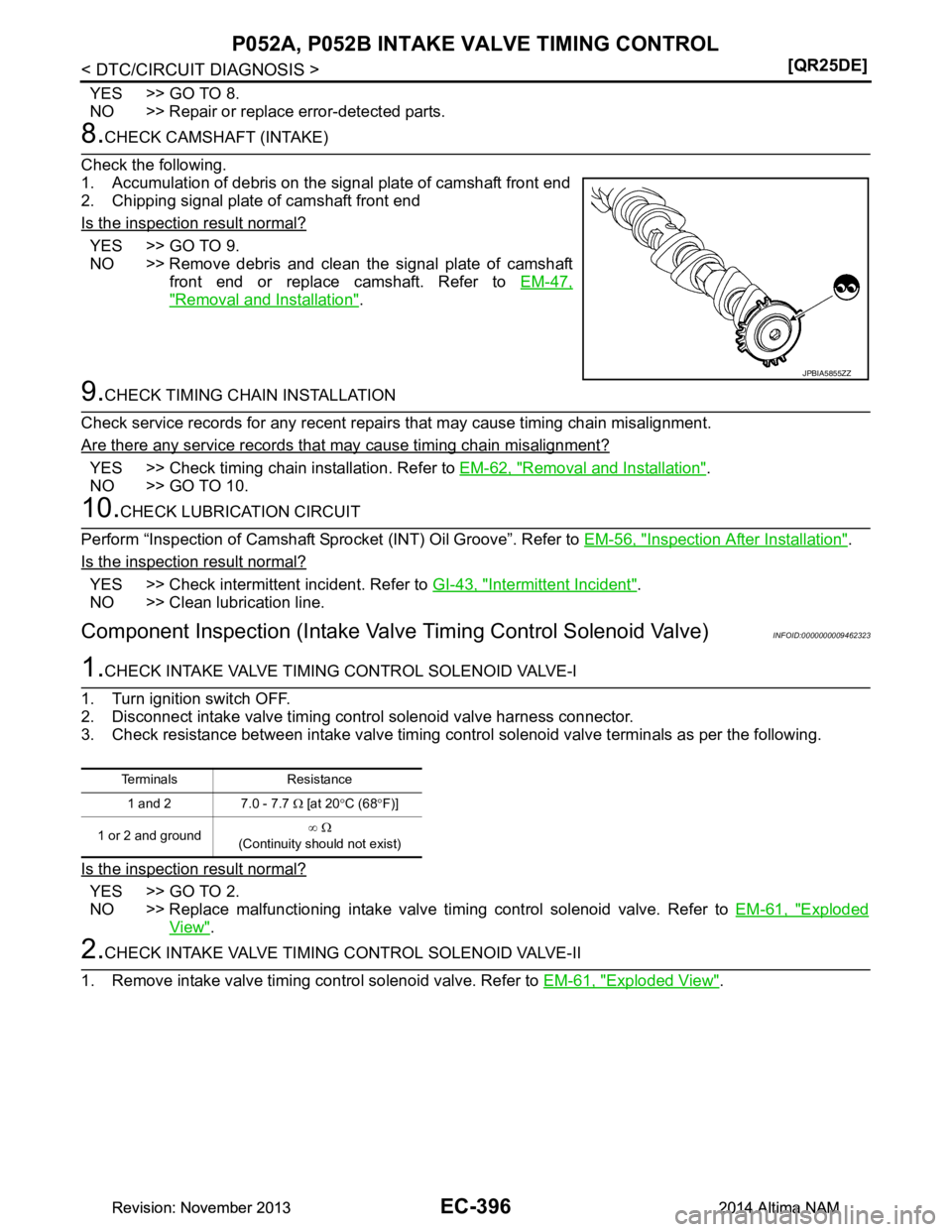
8.CHECK CAMSHAFT (INTAKE)
Check the following.
1. Accumulation of debris on the signal plate of camshaft front end
2. Chipping signal plate of camshaft front end
Is the inspection result normal?
YES >> GO TO 9.
NO >> Remove debris and clean the signal plate of camshaft
front end or replace camshaft. Refer to EM-47,
"Removal and Installation".
9.CHECK TIMING CHAIN INSTALLATION
Check service records for any recent repair s that may cause timing chain misalignment.
Are there any service records that may cause timing chain misalignment?
YES >> Check timing chain installation. Refer to EM-62, "Removal and Installation".
NO >> GO TO 10.
10.CHECK LUBRICATION CIRCUIT
Perform “Inspection of Camshaft Spro cket (INT) Oil Groove”. Refer to EM-56, "Inspection After Installation"
.
Is the inspection result normal?
YES >> Check intermittent incident. Refer to GI-43, "Intermittent Incident".
NO >> Clean lubrication line.
Component Inspection (Intake Valv e Timing Control Solenoid Valve)INFOID:0000000009462323
1.CHECK INTAKE VALVE TIMING CONTROL SOLENOID VALVE-I
1. Turn ignition switch OFF.
2. Disconnect intake valve timing control solenoid valve harness connector.
3. Check resistance between intake valve timing control solenoid valve terminals as per the following.
Is the inspection result normal?
YES >> GO TO 2.
NO >> Replace malfunctioning intake valve timing control solenoid valve. Refer to EM-61, "Exploded
View".
2.CHECK INTAKE VALVE TIMING CONTROL SOLENOID VALVE-II
1. Remove intake valve timing control solenoid valve. Refer to EM-61, "Exploded View"
.
JPBIA5855ZZ
Terminals Resistance
1 and 2 7.0 - 7.7 Ω [at 20 °C (68 °F)]
1 or 2 and ground ∞
Ω
(Continuity should not exist)
Revision: November 20132014 Altima NAMRevision: November 20132014 Altima NAM
Page 1397 of 4801
P052A, P052B INTAKE VALVE TIMING CONTROLEC-397
< DTC/CIRCUIT DIAGNOSIS > [QR25DE]
C
D E
F
G H
I
J
K L
M A
EC
NP
O
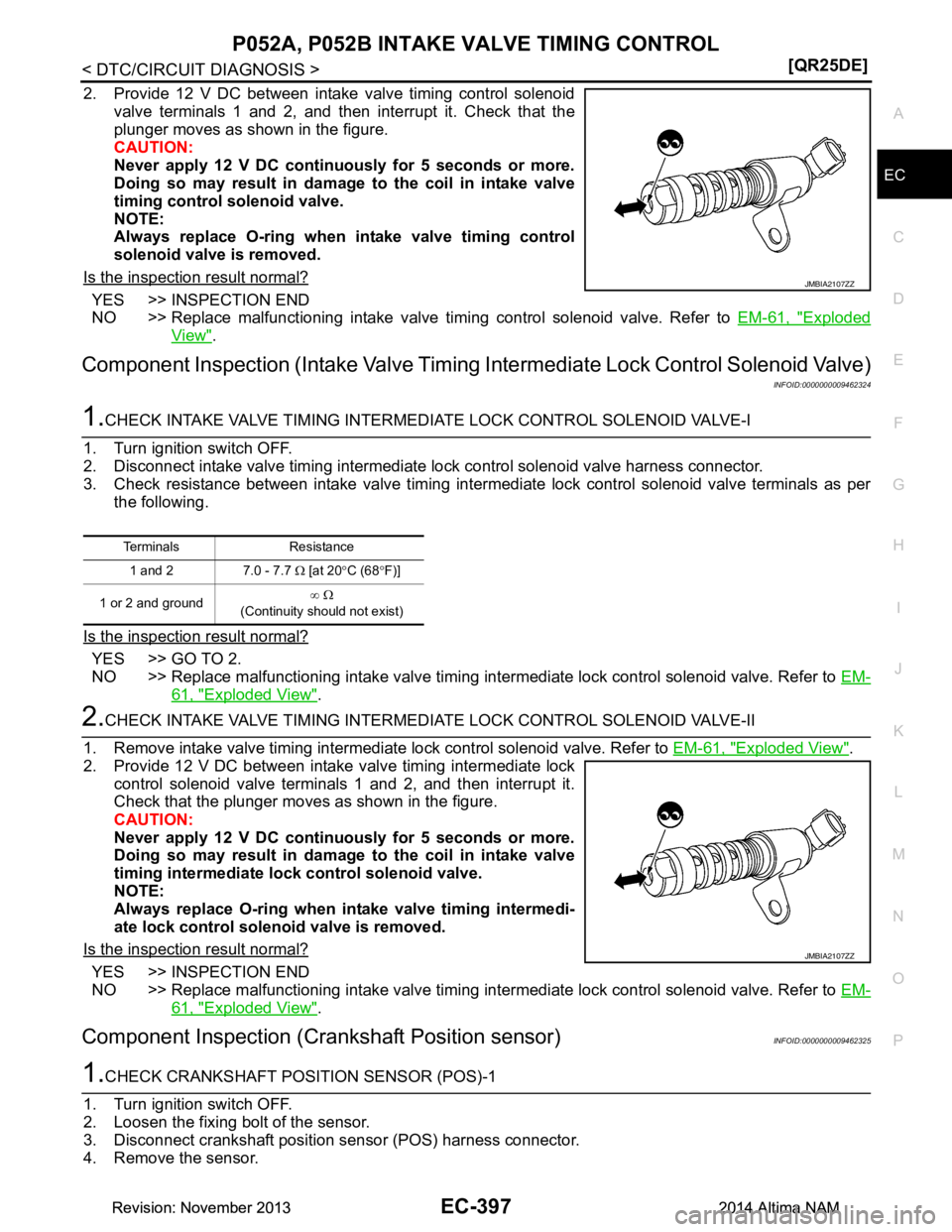
2. Provide 12 V DC between intake valve timing control solenoid
valve terminals 1 and 2, and then interrupt it. Check that the
plunger moves as shown in the figure.
CAUTION:
Never apply 12 V DC continuously for 5 seconds or more.
Doing so may result in damage to the coil in intake valve
timing control solenoid valve.
NOTE:
Always replace O-ring when intake valve timing control
solenoid valve is removed.
Is the inspection result normal?
YES >> INSPECTION END
NO >> Replace malfunctioning intake valve timing control solenoid valve. Refer to EM-61, "Exploded
View".
Component Inspection (Intake Valve Timing Intermediate Lock Control Solenoid Valve)
INFOID:0000000009462324
1.CHECK INTAKE VALVE TIMING INTERMEDIA TE LOCK CONTROL SOLENOID VALVE-I
1. Turn ignition switch OFF.
2. Disconnect intake valve timing intermediate lock control solenoid valve harness connector.
3. Check resistance between intake valve timing intermediate lock control solenoid valve terminals as per the following.
Is the inspection result normal?
YES >> GO TO 2.
NO >> Replace malfunctioning intake valve timing intermediate lock control solenoid valve. Refer to EM-
61, "Exploded View".
2.CHECK INTAKE VALVE TIMING INTERMEDIATE LOCK CONTROL SOLENOID VALVE-II
1. Remove intake valve timing intermediate lock control solenoid valve. Refer to EM-61, "Exploded View"
.
2. Provide 12 V DC between intake valve timing intermediate lock control solenoid valve terminals 1 and 2, and then interrupt it.
Check that the plunger moves as shown in the figure.
CAUTION:
Never apply 12 V DC continuously for 5 seconds or more.
Doing so may result in damage to the coil in intake valve
timing intermediate lock control solenoid valve.
NOTE:
Always replace O-ring when in take valve timing intermedi-
ate lock control solenoid valve is removed.
Is the inspection result normal?
YES >> INSPECTION END
NO >> Replace malfunctioning intake valve timing intermediate lock control solenoid valve. Refer to EM-
61, "Exploded View".
Component Inspection (Crankshaft Position sensor)INFOID:0000000009462325
1.CHECK CRANKSHAFT POSI TION SENSOR (POS)-1
1. Turn ignition switch OFF.
2. Loosen the fixing bolt of the sensor.
3. Disconnect crankshaft position sensor (POS) harness connector.
4. Remove the sensor.
JMBIA2107ZZ
Terminals Resistance
1 and 2 7.0 - 7.7 Ω [at 20 °C (68 °F)]
1 or 2 and ground ∞
Ω
(Continuity should not exist)
JMBIA2107ZZ
Revision: November 20132014 Altima NAMRevision: November 20132014 Altima NAM
Page 1398 of 4801
EC-398
< DTC/CIRCUIT DIAGNOSIS >[QR25DE]
P052A, P052B INTAKE VALVE TIMING CONTROL
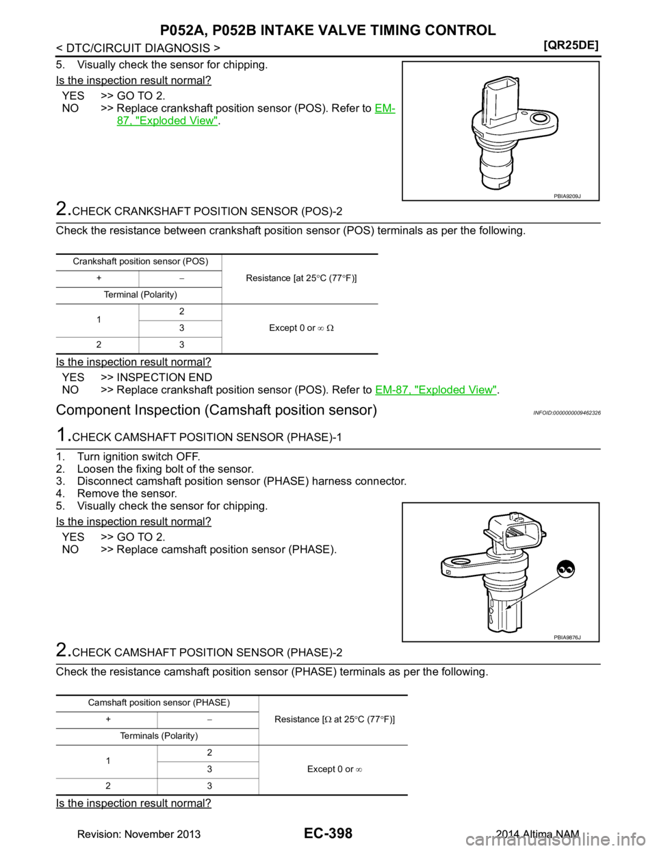
5. Visually check the sensor for chipping.
Is the inspection result normal?
YES >> GO TO 2.
NO >> Replace crankshaft position sensor (POS). Refer to EM-
87, "Exploded View".
2.CHECK CRANKSHAFT POSITION SENSOR (POS)-2
Check the resistance between crankshaft position s ensor (POS) terminals as per the following.
Is the inspection result normal?
YES >> INSPECTION END
NO >> Replace crankshaft position sensor (POS). Refer to EM-87, "Exploded View"
.
Component Inspection (Camshaft position sensor)INFOID:0000000009462326
1.CHECK CAMSHAFT POSI TION SENSOR (PHASE)-1
1. Turn ignition switch OFF.
2. Loosen the fixing bolt of the sensor.
3. Disconnect camshaft position s ensor (PHASE) harness connector.
4. Remove the sensor.
5. Visually check the sensor for chipping.
Is the inspection result normal?
YES >> GO TO 2.
NO >> Replace camshaft position sensor (PHASE).
2.CHECK CAMSHAFT POSI TION SENSOR (PHASE)-2
Check the resistance camshaft position sensor (PHASE) terminals as per the following.
Is the inspection result normal?
PBIA9209J
Crankshaft position sensor (POS) Resistance [at 25°C (77 °F)]
+ −
Terminal (Polarity)
1 2
Except 0 or ∞ Ω
3
23
PBIA9876J
Camshaft position sensor (PHASE) Resistance [Ω at 25 °C (77 °F)]
+ −
Terminals (Polarity)
1 2
Except 0 or ∞
3
23
Revision: November 20132014 Altima NAMRevision: November 20132014 Altima NAM
Page 1399 of 4801
P052A, P052B INTAKE VALVE TIMING CONTROLEC-399
< DTC/CIRCUIT DIAGNOSIS > [QR25DE]
C
D E
F
G H
I
J
K L
M A
EC
NP
O
YES >> INSPECTION END
NO >> Replace camshaft position sensor (PHASE). Refer to EM-47, "Removal and Installation"
.
Revision: November 20132014 Altima NAMRevision: November 20132014 Altima NAM
Page 1413 of 4801
P1078 EVT CONTROL POSITION SENSOREC-413
< DTC/CIRCUIT DIAGNOSIS > [QR25DE]
C
D E
F
G H
I
J
K L
M A
EC
NP
O
P1078 EVT CONTROL POSITION SENSOR
DTC LogicINFOID:0000000009462342
DTC DETECTION LOGIC
DTC CONFIRMATION PROCEDURE
1.PRECONDITIONING
If DTC Confirmation Procedure has been previously conducted, always perform the following procedure
before conducting the next test.
1. Turn ignition switch OFF and wait at least 10 seconds.
2. Turn ignition switch ON.
3. Turn ignition switch OFF and wait at least 10 seconds.
>> GO TO 2.
2.PERFORM DTC CONFIRMATION PROCEDURE
1. Start engine and let it idle for 10 seconds.
2. Check 1st trip DTC.
Is 1st trip DTC detected?
YES >> Proceed to EC-413, "Diagnosis Procedure".
NO >> INSPECTION END
Diagnosis ProcedureINFOID:0000000009462343
1.CHECK EXHAUST VALVE TIMING (EVT) CO NTROL POSITION SENSOR POWER SUPPLY
1. Turn ignition switch OFF.
2. Disconnect exhaust valve timing (EVT) c ontrol position sensor harness connector.
3. Turn ignition switch ON.
4. Check the voltage between EVT control position sensor harness connector and ground.
Is the inspection result normal?
YES >> GO TO 3.
NO >> GO TO 2.
2.CHECK SENSOR POWER SUPPLY 2 CIRCUIT
Perform EC-525, "Diagnosis Procedure"
.
Is inspection result normal?
YES >> Perform the trouble diagnosis for power supply circuit.
NO >> Repair or replace error-detected parts.
3.CHECK EVT CONTROL POSITI ON SENSOR GROUND CIRCUIT
DTC No.CONSULT screen terms
(Trouble diagnosis content) DTC detecting condition Possible cause
P1078 EXH TIM SEN/CIRC-B1
(EXH TIM SEN/CIRC-B1) An excessively high or low
voltage from the sensor is
sent to ECM. • Harness or connectors
(Exhaust valve timing control position sensor circuit is open
or shorted)
• Accumulation of debris to the signal pick-up portion of the camshaft
• Exhaust valve timing control position sensor
• Sensor power supply 2 circuit
+
−Vo l ta g e
(Approx.)
EVT sensor
Connector Terminal F58 1 Ground 5 V
Revision: November 20132014 Altima NAMRevision: November 20132014 Altima NAM
Page 1415 of 4801
P1078 EVT CONTROL POSITION SENSOREC-415
< DTC/CIRCUIT DIAGNOSIS > [QR25DE]
C
D E
F
G H
I
J
K L
M A
EC
NP
O
Component InspectionINFOID:0000000009462344
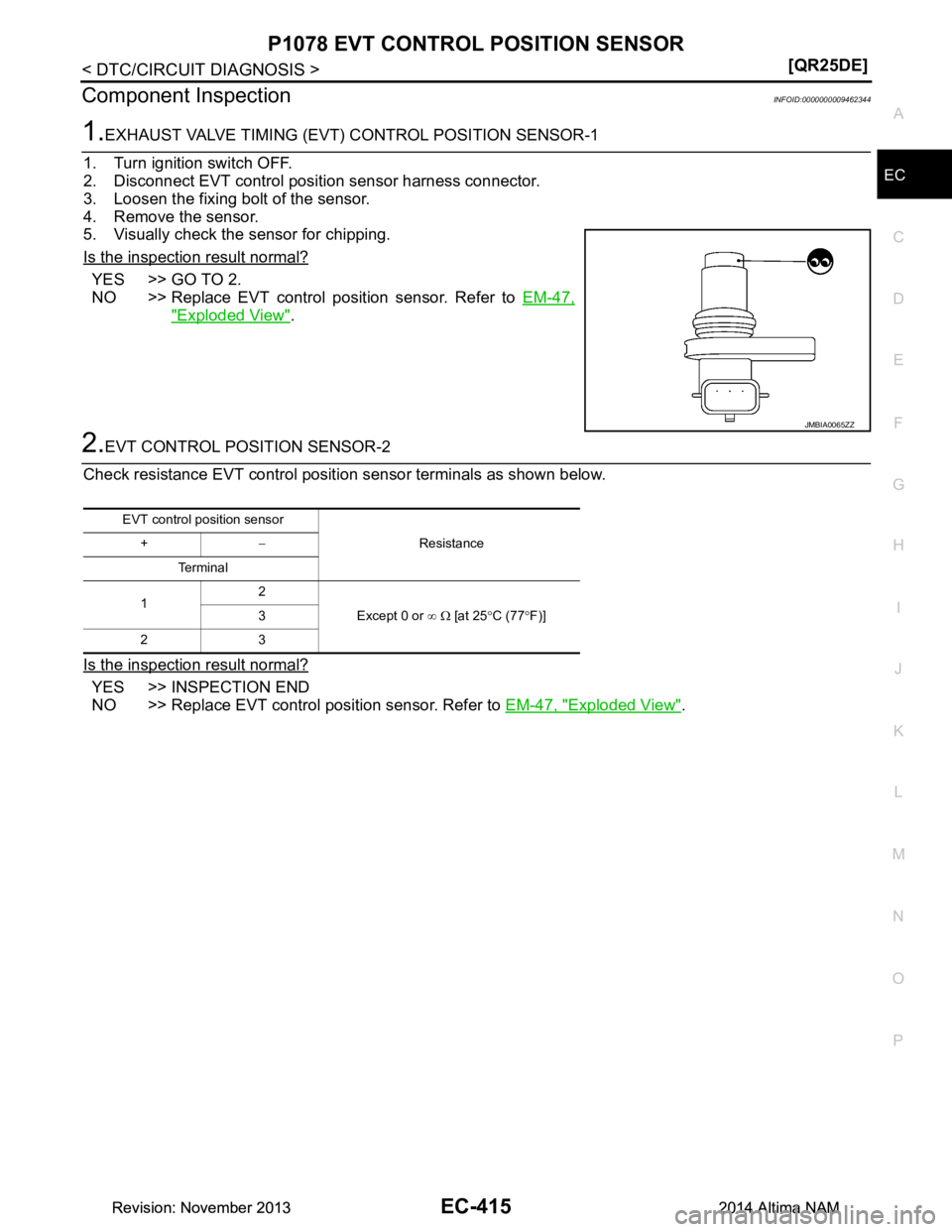
1.EXHAUST VALVE TIMING (EVT)
CONTROL POSITION SENSOR-1
1. Turn ignition switch OFF.
2. Disconnect EVT control posit ion sensor harness connector.
3. Loosen the fixing bolt of the sensor.
4. Remove the sensor.
5. Visually check the sensor for chipping.
Is the inspection result normal?
YES >> GO TO 2.
NO >> Replace EVT control position sensor. Refer to EM-47,
"Exploded View".
2.EVT CONTROL POSITION SENSOR-2
Check resistance EVT control positi on sensor terminals as shown below.
Is the inspection result normal?
YES >> INSPECTION END
NO >> Replace EVT control position sensor. Refer to EM-47, "Exploded View"
.
JMBIA0065ZZ
EVT control position sensor
Resistance
+ −
Te r m i n a l
1 2
Except 0 or ∞ Ω [at 25 °C (77 °F)]
3
23
Revision: November 20132014 Altima NAMRevision: November 20132014 Altima NAM
Page 1527 of 4801
ENGINE CONTROL SYSTEMEC-527
< SYMPTOM DIAGNOSIS > [QR25DE]
C
D E
F
G H
I
J
K L
M A
EC
NP
O
SYMPTOM DIAGNOSIS
ENGINE CONTROL SYSTEM
Symptom TableINFOID:0000000009462460
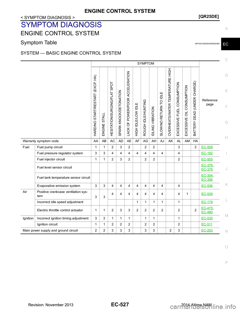
SYSTEM — BASIC ENGINE CONTROL SYSTEM
SYMPTOM
Reference page
HARD/NO START/RESTART (EXCP. HA)
ENGINE STALL
HESITATION/SURGING/FLAT SPOT
SPARK KNOCK/DETONATION
LACK OF POWER/POOR ACCELERATION
HIGH IDLE/LOW IDLE
ROUGH IDLE/HUNTING
IDLING VIBRATION
SLOW/NO RETURN TO IDLE
OVERHEATS/WATER TEMPERATURE HIGH
EXCESSIVE FUEL CONSUMPTION
EXCESSIVE OIL CONSUMPTION
BATTERY DEAD (UNDER CHARGE)
Warranty symptom code AA AB AC AD AE AF AG AH AJ AK AL AM HA
Fuel Fuel pump circuit 11232 22 3 2 EC-508
Fuel pressure regulator system 334444444 4EC-182
Fuel injector circuit 11232 22 2EC-505
Fuel level sensor circuitEC-376,
EC-378
Fuel tank temperature sensor circuit EC-304,
EC-306
Evaporative emission system 334444444 4 EC-536
Air Positive crankcase ventilation sys-
tem 334444444 41
EC-539
Incorrect idle speed adjustment 1 1 1 1 1 EC-179
Electric throttle control actuator 112332222 2 2EC-475,
EC-480
IgnitionIncorrect ignition timing adjustment33111 11 1 EC-535
Ignition circuit 11222 22 2EC-511
Main power supply and ground circuit 22333 33 23 EC-203
Revision: November 20132014 Altima NAMRevision: November 20132014 Altima NAM