timing NISSAN TEANA 2014 Service Manual
[x] Cancel search | Manufacturer: NISSAN, Model Year: 2014, Model line: TEANA, Model: NISSAN TEANA 2014Pages: 4801, PDF Size: 51.2 MB
Page 1689 of 4801
HOW TO SET SRT CODEEC-689
< BASIC INSPECTION > [VQ35DE]
C
D E
F
G H
I
J
K L
M A
EC
NP
O
HOW TO SET SRT CODE
DescriptionINFOID:0000000009462564
OUTLINE
In order to set all SRTs, the self-diagnoses as in
the “SRT ITEM” table must have been performed at least
once. Each diagnosis may require actual driving for a long period of time under various conditions.
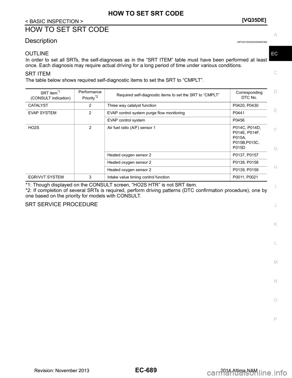
SRT ITEM
The table below shows required self-diagnostic items to set the SRT to “CMPLT”.
*1: Though displayed on the CONSULT screen, “HO2S HTR” is not SRT item.
*2: If completion of several SRTs is required, perfo rm driving patterns (DTC confirmation procedure), one by
one based on the priority for models with CONSULT.
SRT SERVICE PROCEDURE
SRT item*1
(CONSULT indication) Performance
Priority*2Required self-diagnostic items to set the SRT to “CMPLT” Corresponding
DTC No.
CATALYST 2 Three way catalyst function P0420, P0430
EVAP SYSTEM 2 EVAP control system purge flow monitoring P0441
EVAP control system P0456
HO2S 2 Air fuel ratio (A/F) sensor 1 P014C, P014D, P014E, P014F,
P015A,
P015B,P015C,
P015D
Heated oxygen sensor 2 P0137, P0157
Heated oxygen sensor 2 P0138, P0158
Heated oxygen sensor 2 P0139, P0159
EGR/VVT SYSTEM 3 Intake value timing control function P0011, P0021
Revision: November 20132014 Altima NAMRevision: November 20132014 Altima NAM
Page 1706 of 4801
EC-706
< DTC/CIRCUIT DIAGNOSIS >[VQ35DE]
TROUBLE DIAGNOSIS - SPECIFICATION VALUE
15.DISCONNECT AND RECONNE
CT ECM HARNESS CONNECTOR
1. Stop the engine.
2. Disconnect ECM harness connector. Check pin terminal and connector for damage, and then reconnect it.
>> GO TO 16.
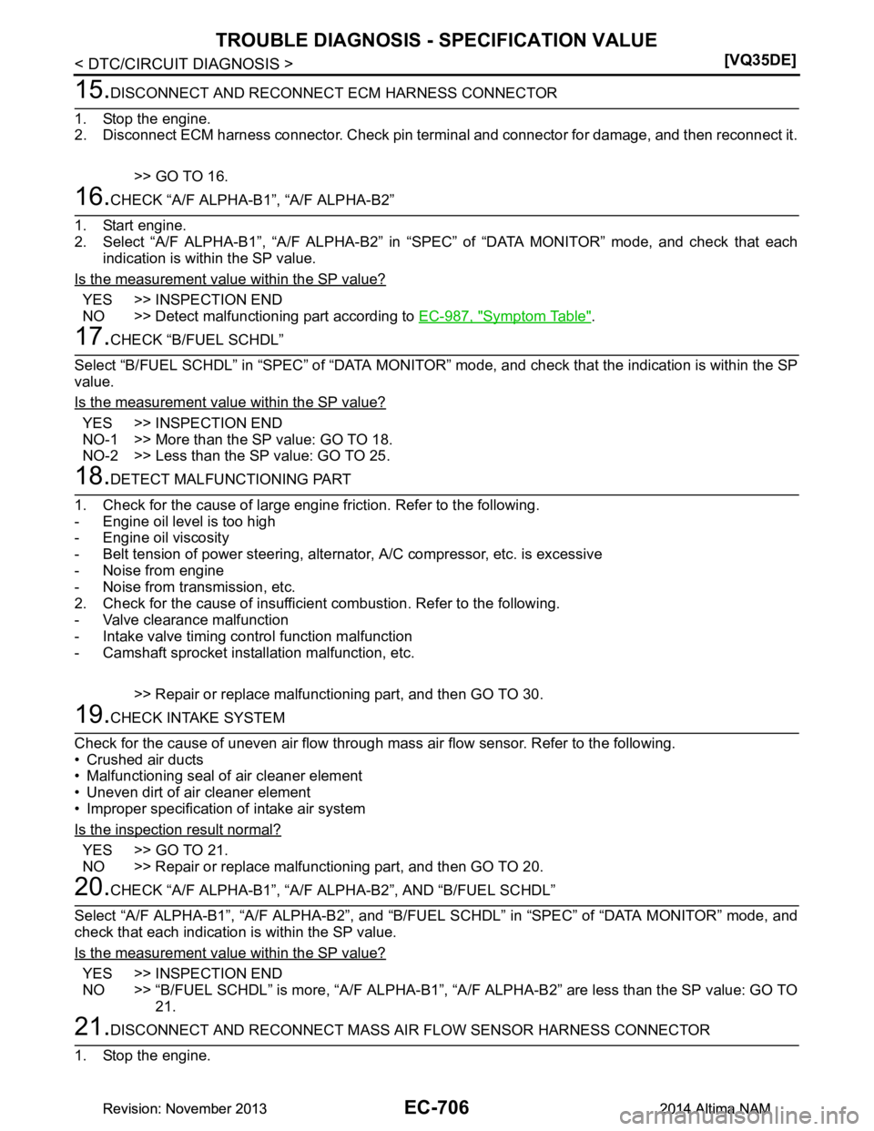
16.CHECK “A/F ALPHA-B1”, “A/F ALPHA-B2”
1. Start engine.
2. Select “A/F ALPHA-B1”, “A/F ALPHA-B2” in “ SPEC” of “DATA MONITOR” mode, and check that each
indication is within the SP value.
Is the measurement value within the SP value?
YES >> INSPECTION END
NO >> Detect malfunctioning part according to EC-987, "Symptom Table"
.
17.CHECK “B/FUEL SCHDL”
Select “B/FUEL SCHDL” in “SPEC” of “DATA MONITOR” mode, and check that the indication is within the SP
value.
Is the measurement value within the SP value?
YES >> INSPECTION END
NO-1 >> More than the SP value: GO TO 18.
NO-2 >> Less than the SP value: GO TO 25.
18.DETECT MALFUNCTIONING PART
1. Check for the cause of large engine friction. Refer to the following.
- Engine oil level is too high
- Engine oil viscosity
- Belt tension of power steering, alternat or, A/C compressor, etc. is excessive
- Noise from engine
- Noise from transmission, etc.
2. Check for the cause of insufficient combustion. Refer to the following.
- Valve clearance malfunction
- Intake valve timing control function malfunction
- Camshaft sprocket installation malfunction, etc.
>> Repair or replace malfunctioning part, and then GO TO 30.
19.CHECK INTAKE SYSTEM
Check for the cause of uneven air flow through mass air flow sensor. Refer to the following.
• Crushed air ducts
• Malfunctioning seal of air cleaner element
• Uneven dirt of air cleaner element
• Improper specification of intake air system
Is the inspection result normal?
YES >> GO TO 21.
NO >> Repair or replace malfunctioning part, and then GO TO 20.
20.CHECK “A/F ALPHA-B1”, “A/F ALPHA-B2”, AND “B/FUEL SCHDL”
Select “A/F ALPHA-B1”, “A/F ALPHA-B2”, and “B/F UEL SCHDL” in “SPEC” of “DATA MONITOR” mode, and
check that each indication is within the SP value.
Is the measurement value within the SP value?
YES >> INSPECTION END
NO >> “B/FUEL SCHDL” is more, “A/F ALPHA-B1”, “A /F ALPHA-B2” are less than the SP value: GO TO
21.
21.DISCONNECT AND RECONNECT MASS AIR FLOW SENSOR HARNESS CONNECTOR
1. Stop the engine.
Revision: November 20132014 Altima NAMRevision: November 20132014 Altima NAM
Page 1715 of 4801
P0011, P0021 IVT CONTROLEC-715
< DTC/CIRCUIT DIAGNOSIS > [VQ35DE]
C
D E
F
G H
I
J
K L
M A
EC
NP
O
P0011, P0021 IVT CONTROL
DTC LogicINFOID:0000000009462580
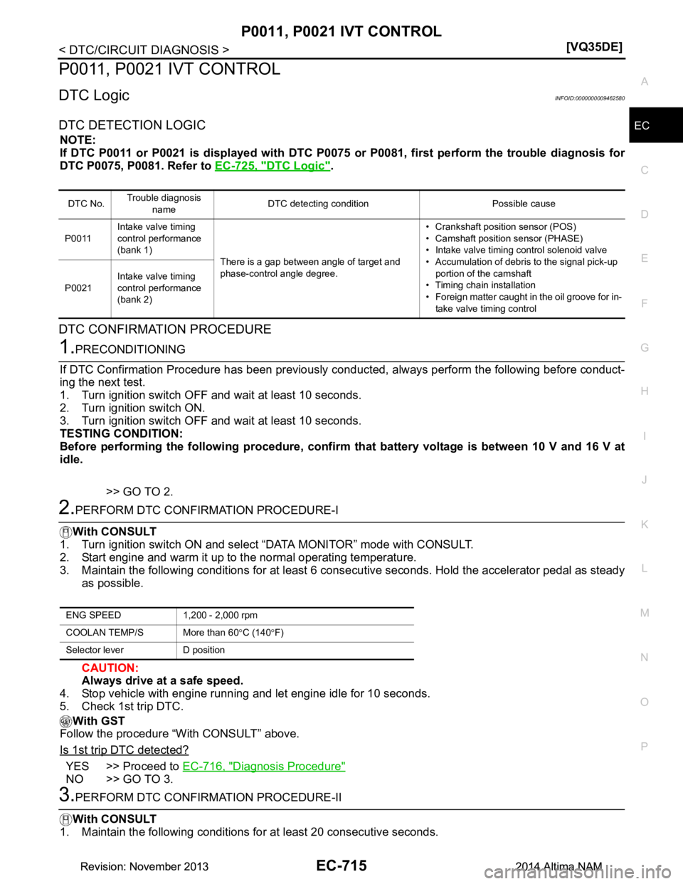
DTC DETECTION LOGIC
NOTE:
If DTC P0011 or P0021 is displayed with DTC P0075 or P0081, first perform the trouble diagnosis for
DTC P0075, P0081. Refer to EC-725, "DTC Logic"
.
DTC CONFIRMATION PROCEDURE
1.PRECONDITIONING
If DTC Confirmation Procedure has been previously conduc ted, always perform the following before conduct-
ing the next test.
1. Turn ignition switch OFF and wait at least 10 seconds.
2. Turn ignition switch ON.
3. Turn ignition switch OFF and wait at least 10 seconds.
TESTING CONDITION:
Before performing the following procedure, confirm that battery voltage is between 10 V and 16 V at
idle.
>> GO TO 2.
2.PERFORM DTC CONFIRMATION PROCEDURE-I
With CONSULT
1. Turn ignition switch ON and select “DATA MONITOR” mode with CONSULT.
2. Start engine and warm it up to the normal operating temperature.
3. Maintain the following conditions for at least 6 c onsecutive seconds. Hold the accelerator pedal as steady
as possible.
CAUTION:
Always drive at a safe speed.
4. Stop vehicle with engine running and let engine idle for 10 seconds.
5. Check 1st trip DTC.
With GST
Follow the procedure “With CONSULT” above.
Is 1st trip DTC detected?
YES >> Proceed to EC-716, "Diagnosis Procedure"
NO >> GO TO 3.
3.PERFORM DTC CONFIRMATION PROCEDURE-II
With CONSULT
1. Maintain the following conditions for at least 20 consecutive seconds.
DTC No. Trouble diagnosis
name DTC detecting condition Possible cause
P0011 Intake valve timing
control performance
(bank 1)
There is a gap between angle of target and
phase-control angle degree. • Crankshaft position sensor (POS)
• Camshaft positi on sensor (PHASE)
• Intake valve timing control solenoid valve
• Accumulation of debris to the signal pick-up portion of the camshaft
• Timing chain installation
• Foreign matter caught in the oil groove for in- take valve timing control
P0021
Intake valve timing
control performance
(bank 2)
ENG SPEED 1,200 - 2,000 rpm
COOLAN TEMP/S More than 60 °C (140 °F)
Selector lever D position
Revision: November 20132014 Altima NAMRevision: November 20132014 Altima NAM
Page 1716 of 4801
EC-716
< DTC/CIRCUIT DIAGNOSIS >[VQ35DE]
P0011, P0021 IVT CONTROL
CAUTION:
Always drive at a safe speed.
2. Check 1st trip DTC.
With GST
Follow the procedure “With CONSULT” above.
Is 1st trip DTC detected?
YES >> Proceed to EC-716, "Diagnosis Procedure"
NO >> INSPECTION END
Diagnosis ProcedureINFOID:0000000009462581
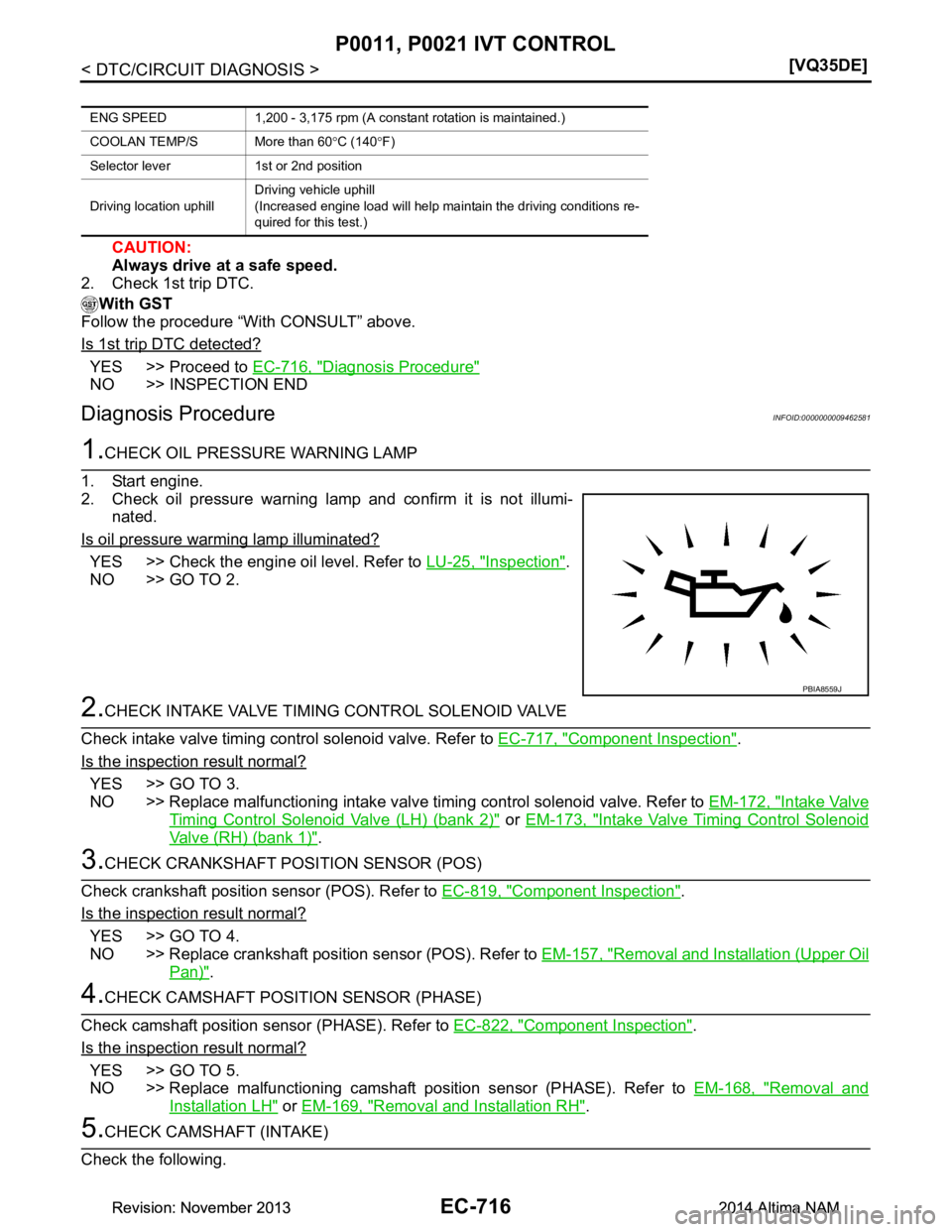
1.CHECK OIL PRESSURE WARNING LAMP
1. Start engine.
2. Check oil pressure warning lamp and confirm it is not illumi- nated.
Is oil pressure warming lamp illuminated?
YES >> Check the engine oil level. Refer to LU-25, "Inspection".
NO >> GO TO 2.
2.CHECK INTAKE VALVE TIMING CONTROL SOLENOID VALVE
Check intake valve timing control solenoid valve. Refer to EC-717, "Component Inspection"
.
Is the inspection result normal?
YES >> GO TO 3.
NO >> Replace malfunctioning intake valve timing control solenoid valve. Refer to EM-172, "Intake Valve
Timing Control Solenoid Valve (LH) (bank 2)" or EM-173, "Intake Valve Timing Control Solenoid
Valve (RH) (bank 1)".
3.CHECK CRANKSHAFT POSI TION SENSOR (POS)
Check crankshaft position sensor (POS). Refer to EC-819, "Component Inspection"
.
Is the inspection result normal?
YES >> GO TO 4.
NO >> Replace crankshaft position sensor (POS). Refer to EM-157, "Removal and Installation (Upper Oil
Pan)".
4.CHECK CAMSHAFT POSITION SENSOR (PHASE)
Check camshaft position sensor (PHASE). Refer to EC-822, "Component Inspection"
.
Is the inspection result normal?
YES >> GO TO 5.
NO >> Replace malfunctioning camshaft position sensor (PHASE). Refer to EM-168, "Removal and
Installation LH" or EM-169, "Removal and Installation RH".
5.CHECK CAMSHAFT (INTAKE)
Check the following.
ENG SPEED 1,200 - 3,175 rpm (A cons tant rotation is maintained.)
COOLAN TEMP/S More than 60 °C (140 °F)
Selector lever 1st or 2nd position
Driving location uphill Driving vehicle uphill
(Increased engine load will help maintain the driving conditions re-
quired for this test.)
PBIA8559J
Revision: November 20132014 Altima NAMRevision: November 20132014 Altima NAM
Page 1717 of 4801
P0011, P0021 IVT CONTROLEC-717
< DTC/CIRCUIT DIAGNOSIS > [VQ35DE]
C
D E
F
G H
I
J
K L
M A
EC
NP
O
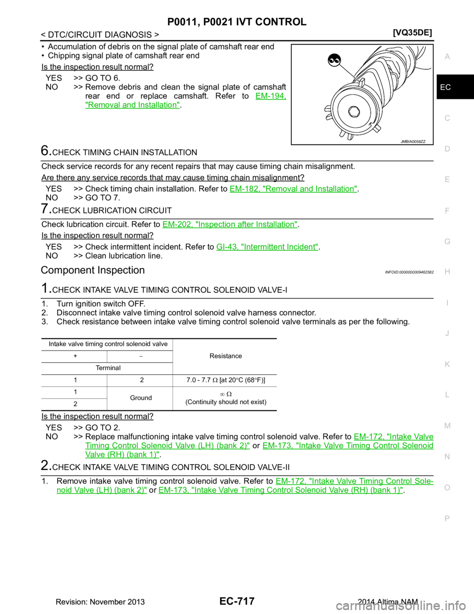
• Accumulation of debris on the signal plate of camshaft rear end
• Chipping signal plate of camshaft rear end
Is the inspection result normal?
YES >> GO TO 6.
NO >> Remove debris and clean the signal plate of camshaft rear end or replace camshaft. Refer to EM-194,
"Removal and Installation".
6.CHECK TIMING CHAIN INSTALLATION
Check service records for any recent repairs that may cause timing chain misalignment.
Are there any service records that may cause timing chain misalignment?
YES >> Check timing chain installation. Refer to EM-182, "Removal and Installation".
NO >> GO TO 7.
7.CHECK LUBRICATION CIRCUIT
Check lubrication circuit. Refer to EM-202, "Inspection after Installation"
.
Is the inspection result normal?
YES >> Check intermittent incident. Refer to GI-43, "Intermittent Incident".
NO >> Clean lubrication line.
Component InspectionINFOID:0000000009462582
1.CHECK INTAKE VALVE TIMING CONTROL SOLENOID VALVE-I
1. Turn ignition switch OFF.
2. Disconnect intake valve timing control solenoid valve harness connector.
3. Check resistance between intake valve timing control solenoid valve terminals as per the following.
Is the inspection result normal?
YES >> GO TO 2.
NO >> Replace malfunctioning intake valve timing control solenoid valve. Refer to EM-172, "Intake Valve
Timing Control Solenoid Valve (LH) (bank 2)" or EM-173, "Intake Valve Timing Control Solenoid
Valve (RH) (bank 1)".
2.CHECK INTAKE VALVE TIMING CONTROL SOLENOID VALVE-II
1. Remove intake valve timing control solenoid valve. Refer to EM-172, "Intake Valve Timing Control Sole-
noid Valve (LH) (bank 2)" or EM-173, "Intake Valve Timing Control Solenoid Valve (RH) (bank 1)".
JMBIA0058ZZ
Intake valve timing control solenoid valve
Resistance
+ −
Te r m i n a l
1 2 7.0 - 7.7 Ω [at 20 °C (68 °F)]
1 Ground ∞
Ω
(Continuity should not exist)
2
Revision: November 20132014 Altima NAMRevision: November 20132014 Altima NAM
Page 1718 of 4801
EC-718
< DTC/CIRCUIT DIAGNOSIS >[VQ35DE]
P0011, P0021 IVT CONTROL
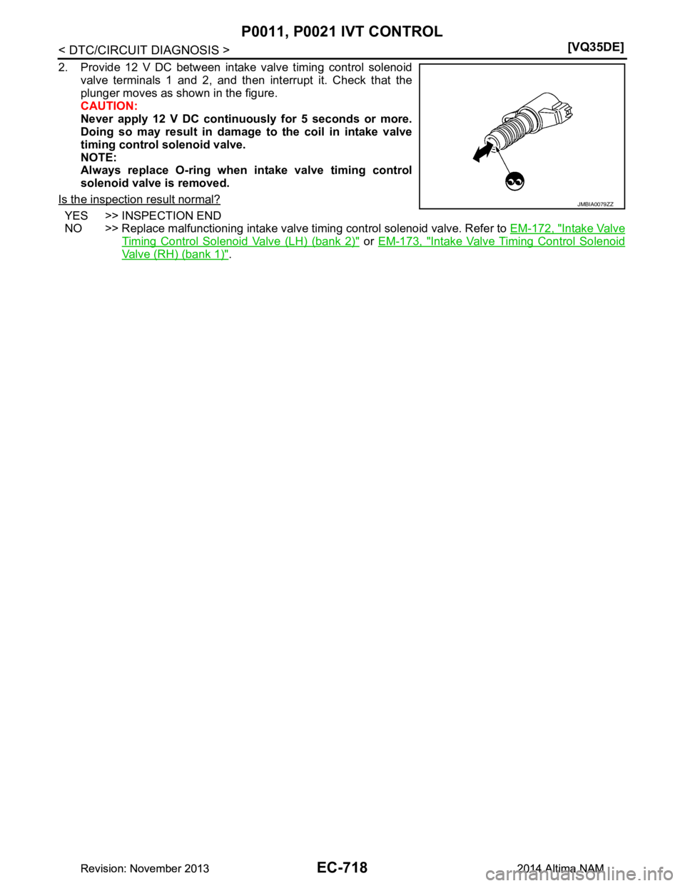
2. Provide 12 V DC between intake valve timing control solenoid
valve terminals 1 and 2, and then interrupt it. Check that the
plunger moves as shown in the figure.
CAUTION:
Never apply 12 V DC continuously for 5 seconds or more.
Doing so may result in damage to the coil in intake valve
timing control solenoid valve.
NOTE:
Always replace O-ring when intake valve timing control
solenoid valve is removed.
Is the inspection result normal?
YES >> INSPECTION END
NO >> Replace malfunctioning intake valve timing control solenoid valve. Refer to EM-172, "Intake Valve
Timing Control Solenoid Valve (LH) (bank 2)" or EM-173, "Intake Valve Timing Control Solenoid
Valve (RH) (bank 1)".
JMBIA0079ZZ
Revision: November 20132014 Altima NAMRevision: November 20132014 Altima NAM
Page 1725 of 4801
P0075, P0081 IVT CONTROL SOLENOID VALVE
EC-725
< DTC/CIRCUIT DIAGNOSIS > [VQ35DE]
C
D E
F
G H
I
J
K L
M A
EC
NP
O
P0075, P0081 IVT CONTROL SOLENOID VALVE
DTC LogicINFOID:0000000009462589
DTC DETECTION LOGIC
DTC CONFIRMATION PROCEDURE
1.PRECONDITIONING
If DTC Confirmation Procedure has been previously conduc ted, always perform the following before conduct-
ing the next test.
1. Turn ignition switch OFF and wait at least 10 seconds.
2. Turn ignition switch ON.
3. Turn ignition switch OFF and wait at least 10 seconds.
>> GO TO 2.
2.PERFORM DTC CONFIRMATION PROCEDURE
1. Start engine and let it idle for 5 seconds.
2. Check 1st trip DTC.
Is 1st trip DTC detected?
YES >> Proceed to EC-725, "Diagnosis Procedure".
NO >> INSPECTION END
Diagnosis ProcedureINFOID:0000000009462590
1.CHECK INTAKE VALVE TIMING CONTRO L SOLENOID VALVE POWER SUPPLY
1. Turn ignition switch OFF.
2. Disconnect intake valve timing (IVT) control solenoid valve harness connector.
3. Turn ignition switch ON.
4. Check the voltage between intake valve timing control solenoid valve harness connector and ground with CONSULT or tester.
Is the inspection result normal?
YES >> GO TO 2.
NO >> Repair open circuit, short to ground or short to power in harness or connectors.
2.CHECK INTAKE VALVE TIMING CONTROL SOLENO ID VALVE OUTPUT SIGNAL CIRCUIT FOR OPEN
AND SHORT
1. Turn ignition switch OFF.
2. Disconnect ECM harness connector.
3. Check the continuity between intake valve timi ng control solenoid valve harness connector and ECM har-
ness connector.
DTC No. Trouble diagnosis name DTC detecting condition Possible cause
P0075 Intake valve timing control so-
lenoid valve (bank 1) circuit An improper voltage is sent to the ECM
through intake valve timing control solenoid
valve. • Harness or connectors
(Intake valve timing control solenoid valve
circuit is open or shorted.)
• Intake valve timing control solenoid valve
P0081 Intake valve timing control so-
lenoid valve (bank 2) circuit
DTC IVT control solenoid valve
Ground Voltage
Bank Connector Terminal
P0075 1 F67 2 Ground Battery voltage
P0081 2 F66 2
Revision: November 20132014 Altima NAMRevision: November 20132014 Altima NAM
Page 1726 of 4801
EC-726
< DTC/CIRCUIT DIAGNOSIS >[VQ35DE]
P0075, P0081 IVT CONTROL SOLENOID VALVE
4. Also check harness for short to ground and short to power.
Is the inspection result normal?
YES >> GO TO 3.
NO >> Repair open circuit, short to ground or short to power in harness or connectors.
3.CHECK INTAKE VALVE TIMING CONTROL SOLENOID VALVE
Check intake valve timing control solenoid valve. Refer to EC-726, "Component Inspection"
.
Is the inspection result normal?
YES >> Check intermittent incident. Refer to GI-43, "Intermittent Incident".
NO >> Replace malfunctioning intake valve timing control solenoid valve. Refer to EM-172, "Intake Valve
Timing Control Solenoid Valve (LH) (bank 2)" or EM-173, "Intake Valve Timing Control Solenoid
Valve (RH) (bank 1)".
Component InspectionINFOID:0000000009462591
1.CHECK INTAKE VALVE TIMING CONTROL SOLENOID VALVE-I
1. Turn ignition switch OFF.
2. Disconnect intake valve timing control solenoid valve harness connector.
3. Check resistance between intake valve timing control solenoid valve terminals as per the following.
Is the inspection result normal?
YES >> GO TO 2.
NO >> Replace malfunctioning intake valve timing control solenoid valve. Refer to EM-172, "Intake Valve
Timing Control Solenoid Valve (LH) (bank 2)" or EM-173, "Intake Valve Timing Control Solenoid
Valve (RH) (bank 1)".
2.CHECK INTAKE VALVE TIMING CONTROL SOLENOID VALVE-II
1. Remove intake valve timing control solenoid valve. Refer to EM-172, "Intake Valve Timing Control Sole-
noid Valve (LH) (bank 2)" or EM-173, "Intake Valve Timing Control Solenoid Valve (RH) (bank 1)".
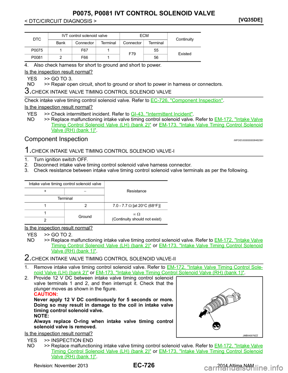
2. Provide 12 V DC between intake valve timing control solenoid valve terminals 1 and 2, and then interrupt it. Check that the
plunger moves as shown in the figure.
CAUTION:
Never apply 12 V DC continuously for 5 seconds or more.
Doing so may result in damage to the coil in intake valve
timing control solenoid valve.
NOTE:
Always replace O-ring when intake valve timing control
solenoid valve is removed.
Is the inspection result normal?
YES >> INSPECTION END
NO >> Replace malfunctioning intake valve timing control solenoid valve. Refer to EM-172, "Intake Valve
Timing Control Solenoid Valve (LH) (bank 2)" or EM-173, "Intake Valve Timing Control Solenoid
Valve (RH) (bank 1)".
DTC IVT control solenoid valve ECM
Continuity
Bank Connector Terminal Connector Terminal
P0075 1 F67 1 F7955
Existed
P0081 2 F66 1 56
Intake valve timing control solenoid valve
Resistance
+ −
Te r m i n a l
1 2 7.0 - 7.7 Ω [at 20 °C (68 °F)]
1 Ground ∞
Ω
(Continuity should not exist)
2
JMBIA0079ZZ
Revision: November 20132014 Altima NAMRevision: November 20132014 Altima NAM
Page 1812 of 4801
EC-812
< DTC/CIRCUIT DIAGNOSIS >[VQ35DE]
P0300, P0301, P030
2, P0303, P0304, P03 05, P0306 MISFIRE
3. Crank engine for approximately 3 seconds, and rec heck whether spark is generated between the spark
plug and the grounded metal portion.
Is the inspection result normal?
YES >> GO TO 7.
NO >> Check ignition coil, power transistor and their circuits. Refer to EC-967, "Diagnosis Procedure"
.
7.CHECK SPARK PLUG
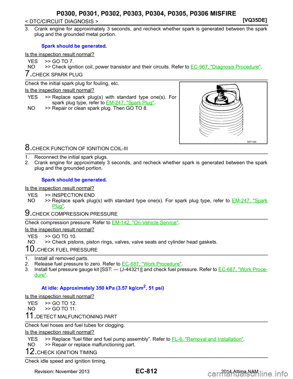
Check the initial spark plug for fouling, etc.
Is the inspection result normal?
YES >> Replace spark plug(s) with standard type one(s). For spark plug type, refer to EM-247, "Spark Plug"
.
NO >> Repair or clean spark plug. Then GO TO 8.
8.CHECK FUNCTION OF IGNITION COIL-III
1. Reconnect the initial spark plugs.
2. Crank engine for approximately 3 seconds, and rec heck whether spark is generated between the spark
plug and the grounded portion.
Is the inspection result normal?
YES >> INSPECTION END
NO >> Replace spark plug(s) with standard type one(s). For spark plug type, refer to EM-247, "Spark
Plug".
9.CHECK COMPRESSION PRESSURE
Check compression pressure. Refer to EM-142, "On-Vehicle Service"
.
Is the inspection result normal?
YES >> GO TO 10.
NO >> Check pistons, piston rings, valves, valve seats and cylinder head gaskets.
10.CHECK FUEL PRESSURE
1. Install all removed parts.
2. Release fuel pressure to zero. Refer to EC-687, "Work Procedure"
.
3. Install fuel pressure gauge kit [SST: — (J-44321)] and check fuel pressure. Refer to EC-687, "Work Proce-
dure".
Is the inspection result normal?
YES >> GO TO 12.
NO >> GO TO 11.
11 .DETECT MALFUNCTIONING PART
Check fuel hoses and fuel tubes for clogging.
Is the inspection result normal?
YES >> Replace “fuel filter and fuel pump assembly”. Refer to FL-6, "Removal and Installation".
NO >> Repair or replace malfunctioning part.
12.CHECK IGNITION TIMING
Check idle speed and ignition timing. Spark should be generated.
SEF156I
Spark should be generated.
At idle: Approximately 350 kPa (3.57 kg/cm
2, 51 psi)
Revision: November 20132014 Altima NAMRevision: November 20132014 Altima NAM
Page 1813 of 4801
P0300, P0301, P0302, P0303, P0304, P0305, P0306 MISFIRE
EC-813
< DTC/CIRCUIT DIAGNOSIS > [VQ35DE]
C
D E
F
G H
I
J
K L
M A
EC
NP
O
For procedure, refer to
EC-675, "Work Procedure".
For specification, refer to EC-998, "Idle Speed"
and EC-998, "Ignition Timing".
Is the inspection result normal?
YES >> GO TO 13.
NO >> Follow the EC-675, "Work Procedure"
.
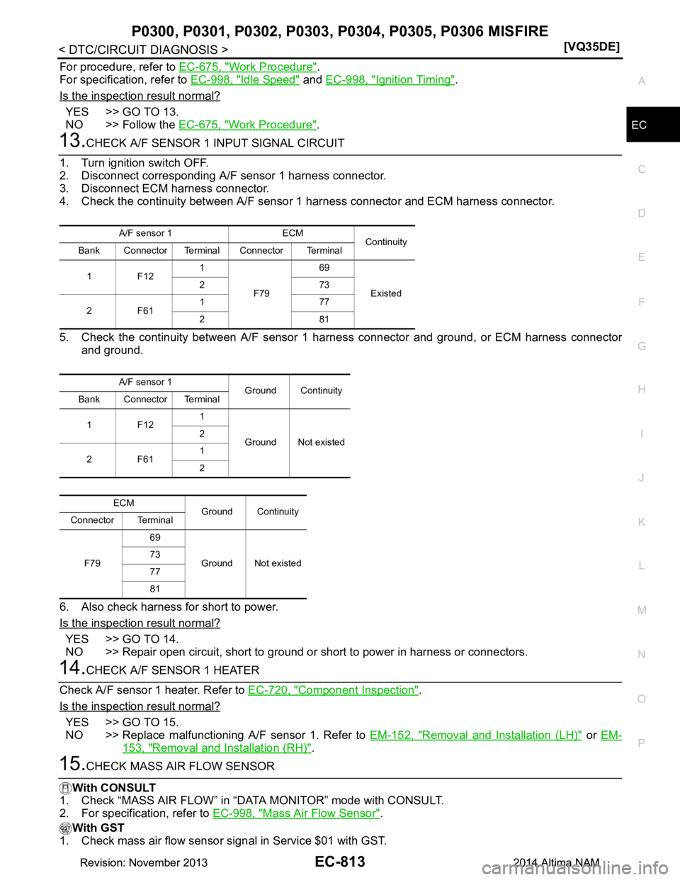
13.CHECK A/F SENSOR 1 INPUT SIGNAL CIRCUIT
1. Turn ignition switch OFF.
2. Disconnect corresponding A/F sensor 1 harness connector.
3. Disconnect ECM harness connector.
4. Check the continuity between A/F sensor 1 harness connector and ECM harness connector.
5. Check the continuity between A/F sensor 1 harness connector and ground, or ECM harness connector
and ground.
6. Also check harness for short to power.
Is the inspection result normal?
YES >> GO TO 14.
NO >> Repair open circuit, short to ground or short to power in harness or connectors.
14.CHECK A/F SENSOR 1 HEATER
Check A/F sensor 1 heater. Refer to EC-720, "Component Inspection"
.
Is the inspection result normal?
YES >> GO TO 15.
NO >> Replace malfunctioning A/F sensor 1. Refer to EM-152, "Removal and Installation (LH)"
or EM-
153, "Removal and Installation (RH)".
15.CHECK MASS AIR FLOW SENSOR
With CONSULT
1. Check “MASS AIR FLOW” in “DATA MONITOR” mode with CONSULT.
2. For specification, refer to EC-998, "Mass Air Flow Sensor"
.
With GST
1. Check mass air flow sensor signal in Service $01 with GST.
A/F sensor 1 ECM Continuity
Bank Connector Terminal Connector Terminal
1F12 1
F79 69
Existed
273
2F61 177
281
A/F sensor 1 Ground Continuity
Bank Connector Terminal
1F12 1
Ground Not existed
2
2F61 1
2
ECM Ground Continuity
Connector Terminal
F79 69
Ground Not existed
73
77
81
Revision: November 20132014 Altima NAMRevision: November 20132014 Altima NAM