Altima NISSAN TEANA 2014 Service Manual
[x] Cancel search | Manufacturer: NISSAN, Model Year: 2014, Model line: TEANA, Model: NISSAN TEANA 2014Pages: 4801, PDF Size: 51.2 MB
Page 2 of 4801

FOREWORD
This manual contains maintenance and repair procedures for the 2014
NISSA
N ALTIMA Sedan.
In order to assure your safety and the efficient functioning of the vehicle,
this manual should be read thoroughly. It is especially important that the
PRECAUTIONS in the GI section be completely understood before starting
any repair task.
All information in this manual is based on the latest product information
at the time of publication. The right is reserved to make changes in specifi-
cations and methods at any time without notice.
IMPORTANT SAFETY NOTICE
The proper performance of service is essential for both the safety of
the technician and the effici ent functioning of the vehicle.
The service methods in this Service Manual are described in such a
manner that the service may be performed safely and accurately.
Service varies with the procedures used, the skills of the technician
and the tools and parts available. Accordingly, anyone using service
procedures, tools or parts which are not specifically recommended
by NISSAN must first be completely satisfied that neither personal
safety nor the vehicle’s safety will be jeopardized by the service
method selected.
Page 4 of 4801

< SERVICE DATA AND SPECIFICATIONS (SDS) 2014
QUICK REFERENCE CHART: ALTIMA
QUICK REFERENCE CHART: ALTIMA
Engine Tune-up Data: QR25DEINFOID:0000000010112422
GENERAL SPECIFICATIONS
DRIVE BELTS
SPARK PLUG
Unit: mm (in)
*: Always check with the Parts Department for the latest parts information.
Engine Tune-up Data: VQ35DEINFOID:0000000010112419
GENERAL SPECIFICATIONS
Cylinder arrangement
In-line 4
Displacement cm
3 (in3) 2,488 (151.82)
Bore and stroke mm (in) 89.0 x 100 (3.50 x 3.94)
Valve arrangement DOHC
Firing order 1-3-4-2
Number of piston rings Compression
2
Oil 1
Compression ratio 10.0:1
Compression pressure
kPa (kg/cm
2, psi) / 250 rpm Standard 1410 (14.4, 204.5)
Minimum
1220 (12.4, 176.9)
Differential limit between cylinders 100 (1.0, 14)
Tension of drive belts Auto adjustment by drive belt auto-tensioner
Make DENSO
Type* StandardFXE20HE11C
Gap (nominal) 1.1 (0.043)
Cylinder arrangement V-6
Displacement cm
3 (cu in) 3,498 (213.45)
Bore and stroke mm (in) 95.5 x 81.4 (3.760 x 3.205)
Valve arrangement DOHC
Firing order 1-2-3-4-5-6
Number of piston rings Compression 2
Oil 1
Number of main bearings 4
Compression ratio 10.3:1
Compression pressure
kPa (kg/cm
2, psi)/300 rpm Standard 1,275 (13.0, 185)
Minimum
981 (10.0, 142)
Differential limit between cylinders 98 (1.0, 14)
Page 5 of 4801
QUICK REFERENCE CHART: ALTIMA
2014
Drive BeltINFOID:0000000010112420
DRIVE BELT
Spark PlugINFOID:0000000010112421
SPARK PLUG
Unit: mm (in)
*: Always check with the Parts Department for the latest parts information.
Front Wheel Alignment (Unladen*1)INFOID:0000000010112418
UNITED STATES
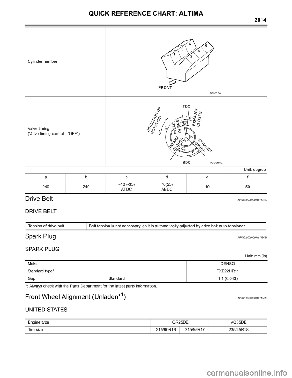
Cylinder number
Valve timing
(Valve timing control - “OFF”)Unit: degree
abcde f
240 240−
10 (-35)
AT D C 70(25)
ABDC 10
50
SEM713A
PBIC0187E
Tension of drive belt Belt tension is not necessary, as it is automatically adjusted by drive belt auto-tensioner.
Make DENSO
Standard type* FXE22HR11
Gap Standard 1.1 (0.043)
Engine type QR25DEVQ35DE
Tire size 215/60R16 215/55R17235/45R18
Page 6 of 4801
< SERVICE DATA AND SPECIFICATIONS (SDS) 2014
QUICK REFERENCE CHART: ALTIMA
*1: Fuel, engine coolant, and lubricants are full. Spare tire, jack, hand tools, and mats are in designated positions.
*2: The RH camber angle shall be -0
° 15 ′± 0 ° 33 ′ (-0.25 °± 0.55° ) with respect to the LH camber angle.
*3: For the caster angle, the difference between right and left against the ground surface shall be ± 0 ° 30 ′ ( ± 0.50° ) maximum.
CANADA
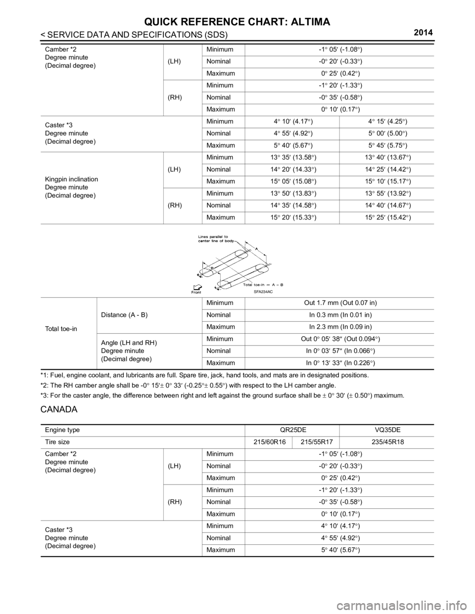
Camber *2
Degree minute
(Decimal degree) (LH)Minimum
-1° 05 ′ (-1.08 °)
Nominal -0° 20 ′ (-0.33 °)
Maximum 0° 25 ′ (0.42 °)
(RH) Minimum
-1° 20 ′ (-1.33 °)
Nominal -0° 35 ′ (-0.58 °)
Maximum 0° 10 ′ (0.17 °)
Caster *3
Degree minute
(Decimal degree) Minimum
4° 10 ′ (4.17 °)4 ° 15 ′ (4.25 °)
Nominal 4° 55 ′ (4.92 °)5 ° 00 ′ (5.00 °)
Maximum 5° 40 ′ (5.67 °)5 ° 45 ′ (5.75 °)
Kingpin inclination
Degree minute
(Decimal degree) (LH)
Minimum
13° 35 ′ (13.58 °)1 3° 40 ′ (1
3.67 °)
Nominal 14° 20 ′ (14.33 °)1 4° 25 ′ (14.42 °)
Maximum 15° 05 ′ (15.08 °)1 5° 10 ′ (15.17 °)
(RH) Minimum
13° 50 ′ (13.83 °)1 3° 55 ′ (13.92 °)
Nominal 14° 35 ′ (14.58 °)1 4° 40 ′ (14.67 °)
Maximum 15° 20 ′ (15.33 °)1 5° 25 ′ (15.42 °)
Total toe-in Distance (A - B)
Minimum
Out 1.7 mm (Out 0.07 in)
Nominal In 0.3 mm (In 0.01 in)
Maximum In 2.3 mm (In 0.09 in)
Angle (LH and RH)
Degree minute
(Decimal degree) Minimum
Out 0° 05′ 38 ″ (Out 0.094° )
Nominal In 0° 03 ′ 57 ″ (In 0.066 °)
Maximum In 0° 13′ 33 ″ (In 0.2
26 °)
SFA234AC
Engine type QR25DEVQ35DE
Tire size 215/60R16 215/55R17235/45R18
Camber *2
Degree minute
(Decimal degree) (LH)Minimum
-1° 05 ′ (-1.08 °)
Nominal -0° 20 ′ (-0.33 °)
Maximum 0° 25 ′ (0.42 °)
(RH) Minimum
-1° 20 ′ (-1.33 °)
Nominal -0° 35 ′ (-0.58 °)
Maximum 0° 10 ′ (0.17 °)
Caster *3
Degree minute
(Decimal degree) Minimum
4° 10 ′ (4.17 °)
Nominal 4° 55 ′ (4.92 °)
Maximum 5° 40 ′ (5.67 °)
Page 7 of 4801
QUICK REFERENCE CHART: ALTIMA
2014
*1: Fuel, engine coolant, and lubricants are full. Spare tire, jack, hand tools, and mats are in designated positions.
*2: The RH camber angle shall be -0° 15 ′± 0 ° 33′ (-0.25 °± 0.55 °) with respect to the LH camber angle.
*3: For the caster angle, the difference between right and left against the ground surface shall be ± 0 ° 30 ′ ( ± 0.50 °) maximum.
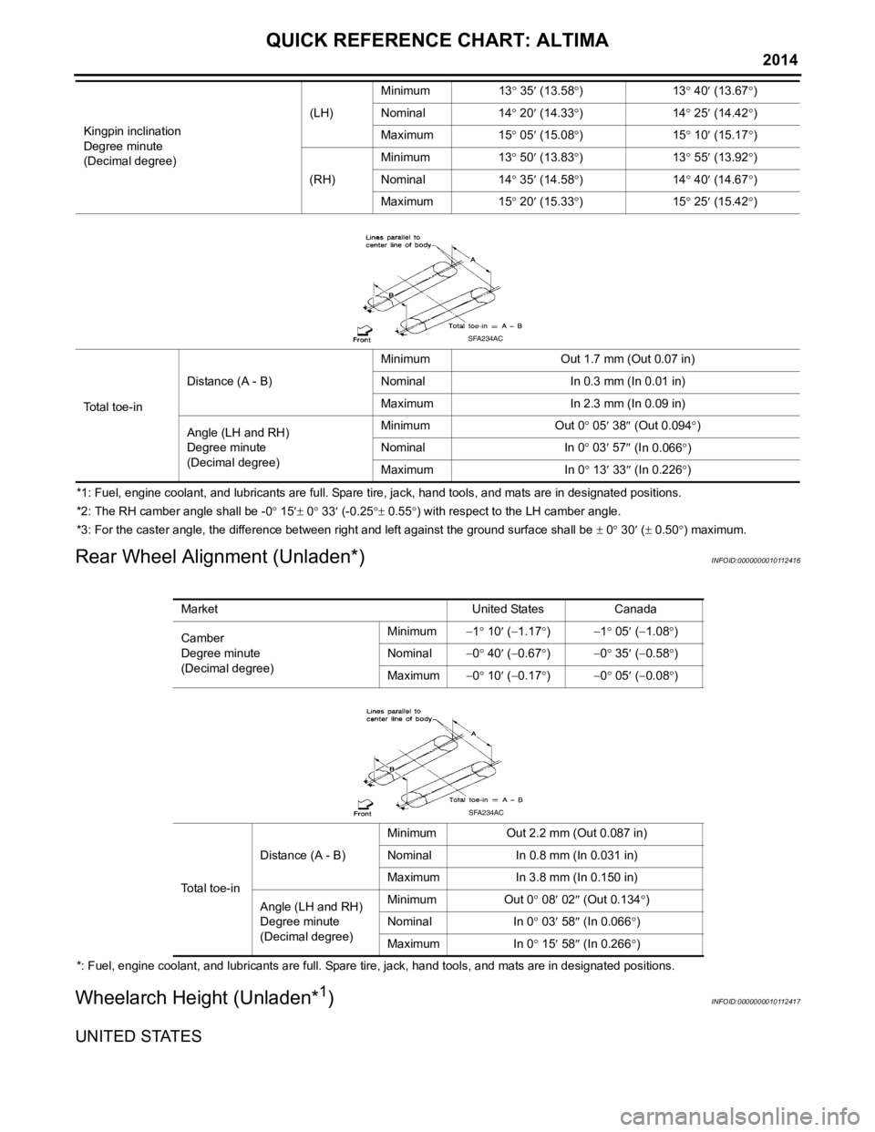
Rear Wheel Alignment (Unladen*)INFOID:0000000010112416
*: Fuel, engine coolant, and lubricants are full. Spare tire, jack, hand tools, and mats are in designated positions.
Wheelarch Height (Unladen*1)INFOID:0000000010112417
UNITED STATES
Kingpin inclination
Degree minute
(Decimal degree) (LH)
Minimum
13° 35 ′ (13.58 °)1 3° 40 ′ (13.67 °)
Nominal 14° 20 ′ (14.33 °)1 4° 25 ′ (14.42 °)
Maximum 15° 05 ′ (15.08 °)1 5° 10 ′ (15.17 °)
(RH) Minimum
13° 50 ′ (13.83 °)1 3° 55 ′ (13.92 °)
Nominal 14° 35 ′ (14.58 °)1 4° 40 ′ (14.67 °)
Maximum 15° 20 ′ (15.33 °)1 5° 25 ′ (15.42 °)
To t a l t o e - i n Distance (A - B)
Minimum
Out 1.7 mm (Out 0.07 in)
Nominal In 0.3 mm (In 0.01 in)
Maximum In 2.3 mm (In 0.09 in)
Angle (LH and RH)
Degree minute
(Decimal degree) Minimum
Out 0° 05 ′ 38 ″ (Out 0.094 °)
Nominal In 0° 03 ′ 57 ″ (I
n 0.066 °)
Maximum In 0° 13 ′ 33 ″ (In 0.226 °)
SFA234AC
Market United StatesCanada
Camber
Degree minute
(Decimal degree) Minimum
−1° 10 ′ ( −1.17 °) −1 ° 05 ′ ( −1.08° )
Nominal −0° 40 ′ ( −0.67 °) −0 ° 35 ′ ( −0.58° )
Maximum −0° 10 ′ ( −0.17 °) −0 ° 05 ′ ( −0.08° )
Total toe-in Distance (A - B)
Minimum
Out 2.2 mm (Out 0.087 in)
Nominal In 0.8 mm (In 0.031 in)
Maximum In 3.8 mm (In 0.150 in)
Angle (LH and RH)
Degree minute
(Decimal degree) Minimum
Out 0° 08′ 02 ″ (Out 0.134° )
Nominal In 0° 03 ′ 58 ″ (In 0.066 °)
Maximum In 0° 15′ 58 ″ (In 0.266 °)
SFA234AC
Page 8 of 4801
< SERVICE DATA AND SPECIFICATIONS (SDS) 2014
QUICK REFERENCE CHART: ALTIMA
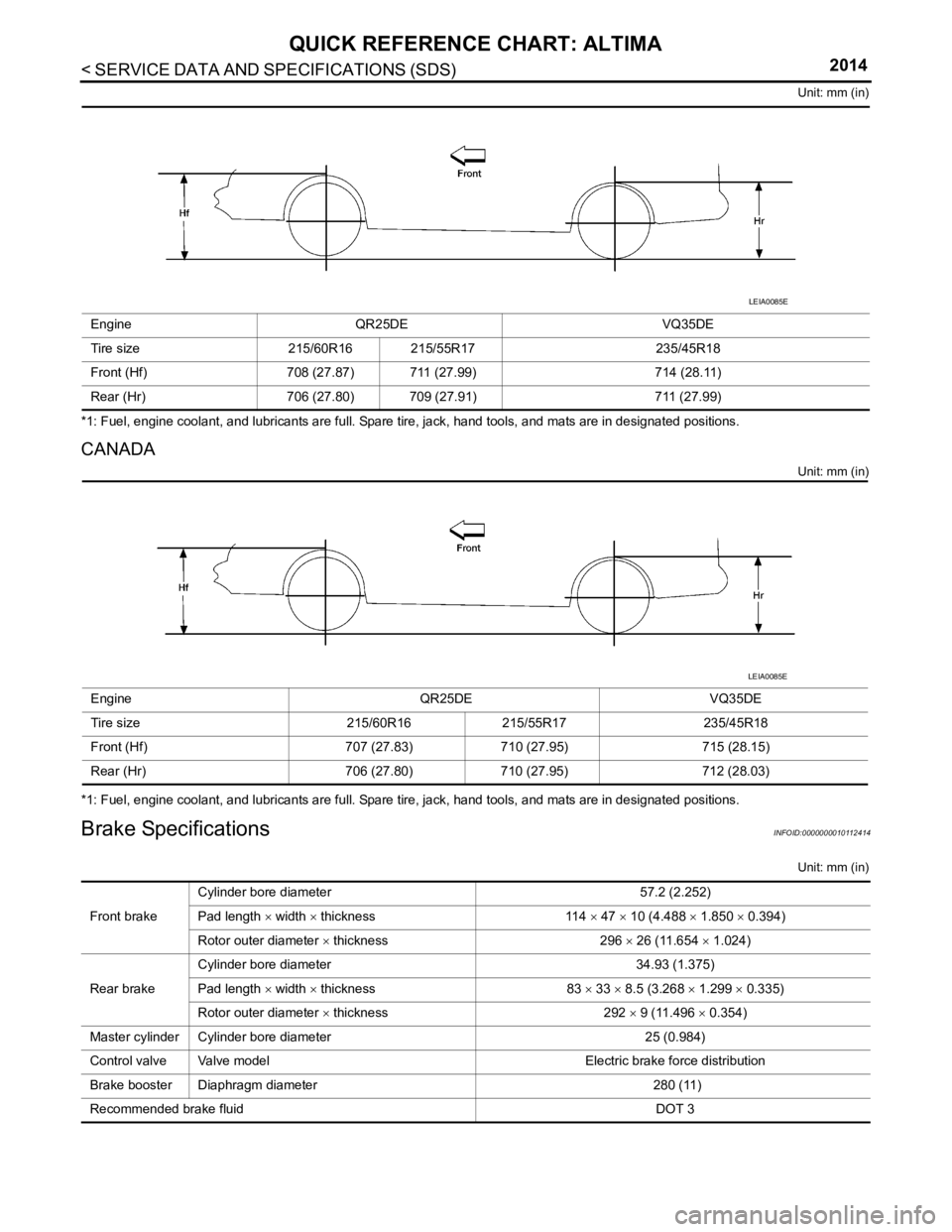
Unit: mm (in)
*1: Fuel, engine coolant, and lubricants are full. Spare tire, jack, hand tools, and mats are in designated positions.
CANADA
Unit: mm (in)
*1: Fuel, engine coolant, and lubricants are full. Spare tire, jack, hand tools, and mats are in designated positions.
Brake SpecificationsINFOID:0000000010112414
Unit: mm (in)
Engine
QR25DE VQ35DE
Tire size 215/60R16 215/55R17 235/45R18
Front (Hf) 708 (27.87) 711 (27.99) 714 (28.11)
Rear (Hr) 706 (27.80) 709 (27.91) 711 (27.99)
LEIA0085E
EngineQR25DEVQ35DE
Tire size 215/60R16215/55R17 235/45R18
Front (Hf) 707 (27.83)710 (27.95) 715 (28.15)
Rear (Hr) 706 (27.80)710 (27.95) 712 (28.03)
LEIA0085E
Front brakeCylinder bore diameter
57.2 (2.252)
Pad length × width × thickness 114 × 47 × 10 (4.488 × 1.850 × 0.394)
Rotor outer diameter × thickness 296 × 26 (11.654 × 1.024)
Rear brake Cylinder bore diameter
34.93 (1.375)
Pad length × width × thickness 83 × 33 × 8.5 (3.268 × 1.299 × 0.335)
Rotor outer diameter × thickness 292 × 9 (11.496 × 0.354)
Master cylinder Cylinder bore diameter 25 (0.984)
Control valve Valve model Electric brake force distribution
Brake booster Diaphragm diameter 280 (11)
Recommended brake fluid DOT 3
Page 9 of 4801
QUICK REFERENCE CHART: ALTIMA
2014
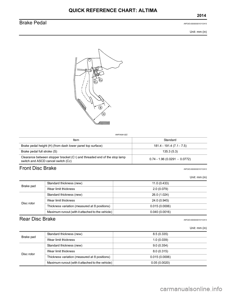
Brake PedalINFOID:0000000010112415
Unit: mm (in)
Front Disc BrakeINFOID:0000000010112412
Unit: mm (in)
Rear Disc BrakeINFOID:0000000010112413
Unit: mm (in)
ItemStandard
Brake pedal height (H) (from dash lower panel top surface) 181.4 - 191.4 (7.1 - 7.5)
Brake pedal full stroke (S) 135.3 (5.3)
Clearance between stopper bracket (C
1) and threaded end of the stop lamp
switch and ASCD cancel switch (C
2) 0.74 - 1.96 (0.0291 - 0.0772)
AWFIA0913ZZ
Brake padStandard thickness (new) 11.0 (0.433)
Wear limit thickness
2.0 (0.079)
Disc rotor Standard thickness (new)
26.0 (1.024)
Wear limit thickness 24.0 (0.945)
Thickness variation (measured at 8 positions) 0.015 (0.0006)
Maximum runout (with it attached to the vehicle) 0.040 (0.0016)
Brake padStandard thickness (new) 8.5 (0.335)
Wear limit thickness
1.0 (0.039)
Disc rotor Standard thickness (new)
9.0 (0.354)
Wear limit thickness 8.0 (0.315)
Thickness variation (measured at 8 positions) 0.015 (0.0006)
Maximum runout (with it attached to the vehicle) 0.05 (0.0020)
Page 10 of 4801

< SERVICE DATA AND SPECIFICATIONS (SDS) 2014
QUICK REFERENCE CHART: ALTIMA
Fluids and Lubricants
INFOID:0000000010112411
Description Capacity (Approximate)
Metric US measure Imp measure
Fuel QR25DE
68 18 gal
15 gal
VQ35DE
Engine oil
Drain and refill With oil filter
change
QR25DE
4.6 4-7/8 qt
4 qt
VQ35DE 4.8 5-1/8 qt
4-1/4 qt
Without oil fil-
ter change QR25DE
4.3 4-1/2 qt
3-3/4 qt
VQ35DE 4.5 4-3/4 qt
4 qt
Dry engine
(engine overhaul) QR25DE
5.4 5-3/4 qt
4-3/4 qt
VQ35DE 5.3 5-5/8 qt
4-5/8 qt
Cooling system
(with reservoir tank
at MAX level) QR25DE
7.9 8-3/8 qt
7 qt
VQ35DE 9.2 9-3/4 qt
8-1/8 qt
CVT fluid RE0F10D
7.4 7-7/8 qt
6-1/2 qt
RE0F10E 8.2 8-5/8 qt
7-1/4 qt
Power steering fluid (E-PSF) 1.1 1-1/8 qt
1 qt
Brake fluid ———
Multi-purpose grease ———
Windshield washer fluid 4.5 4-3/4 qt
4 qt
Air conditioner system refrigerant 0.525 ± 0.025 kg 1.158 ± 0.055 lb 1.158 ± 0.055 lb
Air conditioner system oil 150 m5.1 fl oz
5.3 fl oz
Page 11 of 4801

ACC-1
ENGINE
C
DE
F
G H
I
J
K L
M
SECTION ACC
A
ACC
N
O P
CONTENTS
ACCELERATOR CONTROL SYSTEM
PRECAUTION ................ ...............................2
PRECAUTIONS .............................................. .....2
Precaution for Supplemental Restraint System
(SRS) "AIR BAG" and "SEAT BELT PRE-TEN-
SIONER" ............................................................. ......
2
REMOVAL AND INSTALLATION ................3
ACCELERATOR CONTROL SYSTEM .......... .....3
Exploded View ..................................................... .....3
Removal and Installation ..........................................3
SERVICE DATA AND SPECIFICATIONS
(SDS) ............... ..............................................
5
SERVICE DATA AND SPECIFICATIONS
(SDS) ..................................................................
5
Accelerator Control .............................................. .....5
Revision: November 20132014 Altima NAM
Page 12 of 4801

ACC-2
< PRECAUTION >
PRECAUTIONS
PRECAUTION
PRECAUTIONS
Precaution for Supplemental Restraint System (SRS) "AIR BAG" and "SEAT BELT
PRE-TENSIONER"
INFOID:0000000009951695
The Supplemental Restraint System such as “A IR BAG” and “SEAT BELT PRE-TENSIONER”, used along
with a front seat belt, helps to reduce the risk or severi ty of injury to the driver and front passenger for certain
types of collision. Information necessary to service the system safely is included in the SR and SB section of
this Service Manual.
WARNING:
• To avoid rendering the SRS inopera tive, which could increase the risk of personal injury or death in
the event of a collision which would result in air bag inflation, all maintenance must be performed by
an authorized NISS AN/INFINITI dealer.
• Improper maintenance, including in correct removal and installation of the SRS, can lead to personal
injury caused by unintent ional activation of the system. For re moval of Spiral Cable and Air Bag
Module, see the SR section.
• Do not use electrical test equipmen t on any circuit related to the SRS unless instructed to in this
Service Manual. SRS wiring harn esses can be identified by yellow and/or orange harnesses or har-
ness connectors.
PRECAUTIONS WHEN USING POWER TOOLS (AIR OR ELECTRIC) AND HAMMERS
WARNING:
• When working near the Airbag Diagnosis Sensor Unit or other Airbag System sensors with the Igni-
tion ON or engine running, DO NOT use air or electri c power tools or strike near the sensor(s) with a
hammer. Heavy vibration could activate the sensor( s) and deploy the air bag(s), possibly causing
serious injury.
• When using air or electric power tools or hammers , always switch the Ignition OFF, disconnect the
battery and wait at least three minutes before performing any service.
Revision: November 20132014 Altima NAM