radio NISSAN TEANA 2014 Service Manual
[x] Cancel search | Manufacturer: NISSAN, Model Year: 2014, Model line: TEANA, Model: NISSAN TEANA 2014Pages: 4801, PDF Size: 51.2 MB
Page 151 of 4801
![NISSAN TEANA 2014 Service Manual
PRECAUTIONSBRC-5
< PRECAUTION > [VDC/TCS/ABS]
C
D E
G H
I
J
K L
M A
B
BRC
N
O P
Precaution for Brake ControlINFOID:0000000009463736
• During ABS operation, the brake pedal may vibrate lightly and NISSAN TEANA 2014 Service Manual
PRECAUTIONSBRC-5
< PRECAUTION > [VDC/TCS/ABS]
C
D E
G H
I
J
K L
M A
B
BRC
N
O P
Precaution for Brake ControlINFOID:0000000009463736
• During ABS operation, the brake pedal may vibrate lightly and](/img/5/57390/w960_57390-150.png)
PRECAUTIONSBRC-5
< PRECAUTION > [VDC/TCS/ABS]
C
D E
G H
I
J
K L
M A
B
BRC
N
O P
Precaution for Brake ControlINFOID:0000000009463736
• During ABS operation, the brake pedal may vibrate lightly and a mechanical noise may be heard. This is normal.
• Just after starting vehicle, the brake pedal may vibrate or a motor operating noise may be heard from engine
compartment. This is a normal status of operation check.
• Stopping distance may be longer than that of vehicles without ABS when vehicle drives on rough, gravel, or
snow-covered (fresh, deep snow) roads.
• When an error is indicated by ABS or another warning lamp, collect all necessary information from customer
(what symptoms are present under what conditions) and check for simple causes before starting diagnosis.
Besides electrical system inspection, check boos ter operation, brake fluid level, and fluid leaks.
• If incorrect tire sizes or types are installed on the vehicle or brake pads are not Genuine NISSAN parts, stop-
ping distance or steering stability may deteriorate.
• If there is a radio, antenna or related wiring near control module, ABS function may have a malfunction or
error.
• If aftermarket parts (car stereo, CD player, etc.) have been installed, check for incidents such as harness pinches, open circuits or improper wiring.
• If the following components are replaced with non-genuine components or modified, the VDC OFF indicator
lamp and SLIP indicator lamp may turn on or the VDC system may not operate properly. Components
related to suspension (shock absorbers, struts, springs , bushings, etc.), tires, wheels (exclude specified
size), components related to brake system (pads, roto rs, calipers, etc.), components related to engine (muf-
fler, ECM, etc.), components related to body reinforcement (roll bar, tower bar, etc.).
• Driving with broken or excessively worn suspensi on components, tires or brake system components may
cause the VDC OFF indicator lamp and the SLIP indicator lamp to turn on, and the VDC system may not
operate properly.
• When the TCS or VDC is activated by sudden acceleration or sudden turn, some noise may occur. The
noise is a result of the normal operation of the TCS and VDC.
• When driving on roads which have extreme slopes (such as mountainous roads) or high banks (such as sharp curves on a freeway), the VDC may not operate no rmally, or the VDC warning lamp and the SLIP indi-
cator lamp may turn on. This is not a problem if normal operation can be resumed after restarting the engine.
• Sudden turns (such as spin turns, acceleration turns), drifting, etc. with VDC turned off may cause the yaw rate/side/decel G sensor to indicate a problem. This is not a problem if normal operation can be resumed
after restarting the engine.
Precaution for CAN SystemINFOID:0000000009463737
• Do not apply voltage of 7.0V or higher to terminal to be measured.
• Maximum open terminal voltage of tester in use must be less than 7.0V.
• Before checking harnesses, turn ignition switch OFF and disconnect battery negative cable.
• Area to be repaired must be soldered and wrapped with tape. Make sure that fraying of twisted wire is within 110 mm (4.33 in).
PKIA0306E
Revision: November 20132014 Altima NAMRevision: November 20132014 Altima NAM
Page 267 of 4801
![NISSAN TEANA 2014 Service Manual
PEDAL VIBRATION OR ABS OPERATION SOUND OCCURS
BRC-121
< SYMPTOM DIAGNOSIS > [VDC/TCS/ABS]
C
D E
G H
I
J
K L
M A
B
BRC
N
O P
PEDAL VIBRATION OR ABS OPERATION SOUND OCCURS
Diagnosis ProcedureINFOID: NISSAN TEANA 2014 Service Manual
PEDAL VIBRATION OR ABS OPERATION SOUND OCCURS
BRC-121
< SYMPTOM DIAGNOSIS > [VDC/TCS/ABS]
C
D E
G H
I
J
K L
M A
B
BRC
N
O P
PEDAL VIBRATION OR ABS OPERATION SOUND OCCURS
Diagnosis ProcedureINFOID:](/img/5/57390/w960_57390-266.png)
PEDAL VIBRATION OR ABS OPERATION SOUND OCCURS
BRC-121
< SYMPTOM DIAGNOSIS > [VDC/TCS/ABS]
C
D E
G H
I
J
K L
M A
B
BRC
N
O P
PEDAL VIBRATION OR ABS OPERATION SOUND OCCURS
Diagnosis ProcedureINFOID:0000000009463843
CAUTION:
Under the following conditions, ABS is activated an d vibration is felt when brake pedal is lightly
depressed (just place a foot on i t). However, this is normal.
• When shifting gears
• When driving on slippery road
• During cornering at high speed
• When passing over bumps or grooves [approximately 50 mm (1.97 in) or more]
• When pulling away just after starting engine [a t approximately 10 km/h (6 MPH) or higher]
1.SYMPTOM CHECK 1
Check that there are pedal vibrat ions when the engine is started.
Do symptoms occur?
YES >> GO TO 2
NO >> Inspect the brake pedal.
2.SYMPTOM CHECK 2
Check that there are ABS operati on noises when the engine is started.
Do symptoms occur?
YES >> GO TO 3
NO >> Perform self diagnostic result. Refer to BRC-33, "CONSULT Function (ABS)"
.
3.SYMPTOM CHECK 3
Check symptoms when electrical component (headlamps, etc.) switches are operated.
Do symptoms occur?
YES >> Check if there is a radio, antenna, antenna lead wire, or wiring close to the control unit. If there is,
move it farther away.
NO >> Inspection End.
Revision: November 20132014 Altima NAMRevision: November 20132014 Altima NAM
Page 774 of 4801
DLK-6
< PRECAUTION >
PRECAUTIONS
PRECAUTION
PRECAUTIONS
Precaution for Supplemental Restraint System (SRS) "AIR BAG" and "SEAT BELT
PRE-TENSIONER"
INFOID:0000000009951560
The Supplemental Restraint System such as “A IR BAG” and “SEAT BELT PRE-TENSIONER”, used along
with a front seat belt, helps to reduce the risk or severi ty of injury to the driver and front passenger for certain
types of collision. Information necessary to service the system safely is included in the SR and SB section of
this Service Manual.
WARNING:
• To avoid rendering the SRS inopera tive, which could increase the risk of personal injury or death in
the event of a collision which would result in air bag inflation, all maintenance must be performed by
an authorized NISS AN/INFINITI dealer.
• Improper maintenance, including in correct removal and installation of the SRS, can lead to personal
injury caused by unintent ional activation of the system. For re moval of Spiral Cable and Air Bag
Module, see the SR section.
• Do not use electrical test equipmen t on any circuit related to the SRS unless instructed to in this
Service Manual. SRS wiring harn esses can be identified by yellow and/or orange harnesses or har-
ness connectors.
PRECAUTIONS WHEN USING POWER TOOLS (AIR OR ELECTRIC) AND HAMMERS
WARNING:
• When working near the Airbag Diagnosis Sensor Unit or other Airbag System sensors with the Igni-
tion ON or engine running, DO NOT use air or electri c power tools or strike near the sensor(s) with a
hammer. Heavy vibration could activate the sensor( s) and deploy the air bag(s), possibly causing
serious injury.
• When using air or electric power tools or hammers , always switch the Ignition OFF, disconnect the
battery and wait at least three minutes before performing any service.
Precaution for Procedure without Cowl Top CoverINFOID:0000000009663378
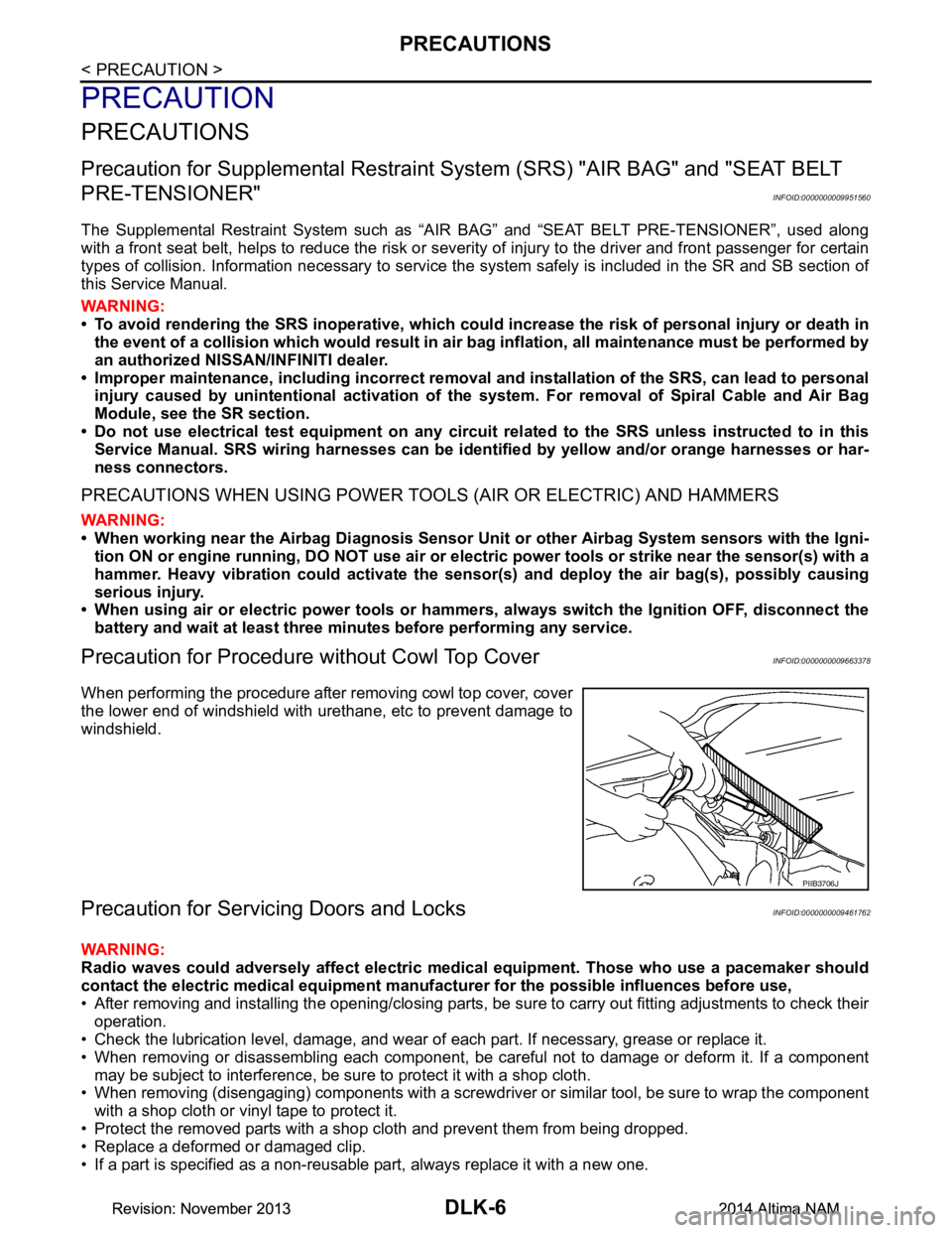
When performing the procedure after removing cowl top cover, cover
the lower end of windshield with urethane, etc to prevent damage to
windshield.
Precaution for Servicing Doors and LocksINFOID:0000000009461762
WARNING:
Radio waves could adversely affect electric medical equipment. Those who use a pacemaker should
contact the electric medical eq uipment manufacturer for the possible influences before use,
• After removing and installing the opening/closing parts, be sure to carry out fitting adjustments to check their
operation.
• Check the lubrication level, damage, and wear of each part. If necessary, grease or replace it.
• When removing or disassembling each component, be careful not to damage or deform it. If a component may be subject to interference, be sure to protect it with a shop cloth.
• When removing (disengaging) components with a screwdriver or similar tool, be sure to wrap the component
with a shop cloth or vinyl tape to protect it.
• Protect the removed parts with a s hop cloth and prevent them from being dropped.
• Replace a deformed or damaged clip.
• If a part is specified as a non-reusable part, always replace it with a new one.
PIIB3706J
Revision: November 20132014 Altima NAMRevision: November 20132014 Altima NAM
Page 787 of 4801
COMPONENT PARTSDLK-19
< SYSTEM DESCRIPTION >
C
D E
F
G H
I
J
L
M A
B
DLK
N
O P
INTELLIGENT KEY SYSTEM : Component DescriptionINFOID:0000000009461769
INTEGRATED HOMELINK TRANSMITTER
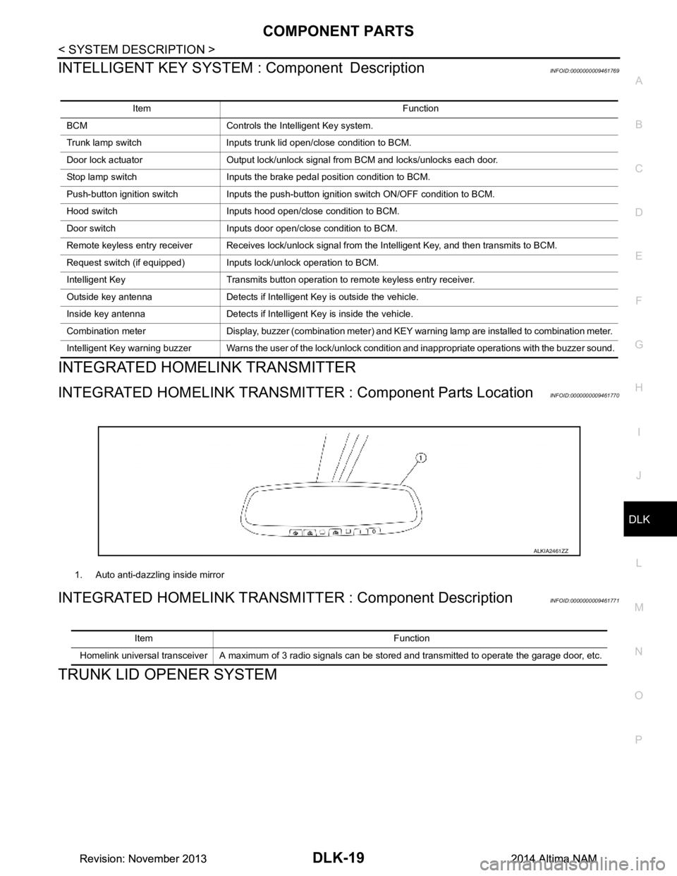
INTEGRATED HOMELINK TRANSMI TTER : Component Parts LocationINFOID:0000000009461770
INTEGRATED HOMELINK TRANSM ITTER : Component DescriptionINFOID:0000000009461771
TRUNK LID OPENER SYSTEM
Item Function
BCM Controls the Intelligent Key system.
Trunk lamp switch Inputs trunk lid open/close condition to BCM.
Door lock actuator Output lock/unlock signal from BCM and locks/unlocks each door.
Stop lamp switch Inputs the brake pedal position condition to BCM.
Push-button ignition switch Inputs the push-button ignition switch ON/OFF condition to BCM.
Hood switch Inputs hood open/close condition to BCM.
Door switch Inputs door open/close condition to BCM.
Remote keyless entry receiver Receives lock/unlock signal from the Intelligent Key, and then transmits to BCM.
Request switch (if equipped) Inputs lock/unlock operation to BCM.
Intelligent Key Transmits button operation to remote keyless entry receiver.
Outside key antenna Detects if Intelligent Key is outside the vehicle.
Inside key antenna Detects if Intelligent Key is inside the vehicle.
Combination meter Display, buzzer (combination meter) and KEY warning lamp are installed to combination meter.
Intelligent Key warning buzzer Warns the user of the lock/unlock condition and inappropriate operations with the buzzer sound.
1. Auto anti-dazzling inside mirror
ALKIA2461ZZ
Item Function
Homelink universal transceiver A maximum of 3 radio signals can be stored and transmitted to operate the garage door, etc.
Revision: November 20132014 Altima NAMRevision: November 20132014 Altima NAM
Page 808 of 4801

DLK-40
< SYSTEM DESCRIPTION >
SYSTEM (INTEGRATED HOMELINK TRANSMITTER)
SYSTEM (INTEGRATED HOMELINK TRANSMITTER)
System DescriptionINFOID:0000000009461791
Item Function
Integrated Homelink
® transmit-
ter A maximum of 3 radio signals can be stored and transmitted to operate the garage door, etc.
Revision: November 20132014 Altima NAMRevision: November 20132014 Altima NAM
Page 918 of 4801
DLK-150
< DTC/CIRCUIT DIAGNOSIS >
HOMELINK UNIVERSAL TRANSCEIVER
HOMELINK UNIVERSAL TRANSCEIVER
DescriptionINFOID:0000000009461904
Homelink universal transceiver can store and transmit a maximum of 3 radio signals.
Allows operation of garage doors, gates, home and office lighting, entry door locks and security system, etc.
Homelink universal transceiver power supply uses vehicl e battery, which enables it to maintain every program
in case battery is discharged or removed.
Component Function CheckINFOID:0000000009461905
1.CHECK FUNCTION
Check that system receiver (garage door opener, et c.) operates with original hand-held transmitter.
Is the inspection result normal?
YES >> GO TO 2
NO >> Receiver or hand-held transmitter is malfunctioning.
2.CHECK ILLUMINATE
1. Turn ignition switch “OFF”.
2. Press each of the transmitter buttons and watch for the red light to illuminate with each button.
Is the inspection result normal?
YES >> GO TO 3
NO >> Refer to DLK-150, "Diagnosis Procedure"
.
3.CHECK TRANSMITTER
Check transmitter with Tool*.
*:For details, refer to Technical Service Bulletin.
Is the inspection result normal?
YES >> Receiver or hand-held transmitter malfunction, not vehicle related.
NO >> Replace auto anti-dazzling inside mirror (homelink universal transceiver). Refer to MIR-19,
"Removal and Installation".
Diagnosis ProcedureINFOID:0000000009461906
Regarding Wiring Diagram information, refer to DLK-49, "Wiring Diagram".
1.CHECK POWER SUPPLY
1. Disconnect auto anti-dazzling inside mirror (homelink universal transceiver) connector.
2. Check voltage between auto anti-dazzling inside mirror (homelink universal transceiver) harness connec-
tor and ground.
Is the inspection result normal?
YES >> GO TO 2
NO >> Check the following. • 10A fuse [No. 1 located in the fuse block (J/B)]
• Harness for open or short between fuse and auto anti-dazzling inside mirror (homelink universal
transceiver).
2.CHECK GROUND CIRCUIT
Auto anti-dazzling inside mirror
(Homelink universal transceiver) connector Terminal Condition
Voltage (V)
(Approx.)
R4 10 Ground Ignition switch position: LOCK Battery voltage
Revision: November 20132014 Altima NAMRevision: November 20132014 Altima NAM
Page 1018 of 4801
![NISSAN TEANA 2014 Service Manual
EC-18
< PRECAUTION >[QR25DE]
PRECAUTIONS
•
When installing C.B. ham radio or a mobile phone, be sure to
observe the following as it m ay adversely affect electronic
control systems depending on in NISSAN TEANA 2014 Service Manual
EC-18
< PRECAUTION >[QR25DE]
PRECAUTIONS
•
When installing C.B. ham radio or a mobile phone, be sure to
observe the following as it m ay adversely affect electronic
control systems depending on in](/img/5/57390/w960_57390-1017.png)
EC-18
< PRECAUTION >[QR25DE]
PRECAUTIONS
•
When installing C.B. ham radio or a mobile phone, be sure to
observe the following as it m ay adversely affect electronic
control systems depending on installation location.
- Keep the antenna as far as possi ble from the electronic con-
trol units.
- Keep the antenna feeder line more than 20 cm (8 in) away
from the harness of electronic controls.
Do not let them run parallel for a long distance.
- Adjust the antenna and feeder line so that the standing-wave
ratio can be kept smaller.
- Be sure to ground the radio to vehicle body.
SEF708Y
Revision: November 20132014 Altima NAMRevision: November 20132014 Altima NAM
Page 1545 of 4801
![NISSAN TEANA 2014 Service Manual
PRECAUTIONSEC-545
< PRECAUTION > [VQ35DE]
C
D E
F
G H
I
J
K L
M A
EC
NP
O
•
B1 indicates bank 1, B2 indicates bank 2 as shown in the fig-
ure.
• Never operate fuel pump when there is no fuel i NISSAN TEANA 2014 Service Manual
PRECAUTIONSEC-545
< PRECAUTION > [VQ35DE]
C
D E
F
G H
I
J
K L
M A
EC
NP
O
•
B1 indicates bank 1, B2 indicates bank 2 as shown in the fig-
ure.
• Never operate fuel pump when there is no fuel i](/img/5/57390/w960_57390-1544.png)
PRECAUTIONSEC-545
< PRECAUTION > [VQ35DE]
C
D E
F
G H
I
J
K L
M A
EC
NP
O
•
B1 indicates bank 1, B2 indicates bank 2 as shown in the fig-
ure.
• Never operate fuel pump when there is no fuel in lines.
• Tighten fuel hose clamps to the specified torque.
• Never depress accelerator pedal when starting.
• Immediately after starting, n ever rev up engine unnecessarily.
• Never rev up engine just prior to shutdown.
• When installing C.B. ham radio or a mobile phone, be sure to
observe the following as it may adversely affect electronic
control systems depending on installation location.
- Keep the antenna as far as possible from the electronic con-
trol units.
- Keep the antenna feeder line more than 20 cm (8 in) away
from the harness of electronic controls.
Never let them run parallel for a long distance.
- Adjust the antenna and feeder line so that the standing-wave
ratio can be kept smaller.
- Be sure to ground the radio to vehicle body.
SEC893C
SEF709Y
SEF708Y
Revision: November 20132014 Altima NAMRevision: November 20132014 Altima NAM
Page 2556 of 4801
GI-28
< PRECAUTION >
PRECAUTIONS
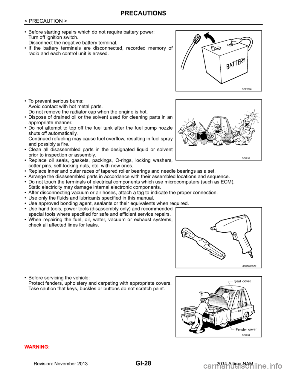
• Before starting repairs which do not require battery power:Turn off ignition switch.
Disconnect the negative battery terminal.
• If the battery terminals are disconnected, recorded memory of
radio and each control unit is erased.
• To prevent serious burns: Avoid contact with hot metal parts.
Do not remove the radiator cap when the engine is hot.
• Dispose of drained oil or the solvent used for cleaning parts in an
appropriate manner.
• Do not attempt to top off the fuel tank after the fuel pump nozzle
shuts off automatically.
Continued refueling may cause fuel overflow, resulting in fuel spray
and possibly a fire.
• Clean all disassembled parts in the designated liquid or solvent
prior to inspection or assembly.
• Replace oil seals, gaskets, packings, O-rings, locking washers, cotter pins, self-locking nuts, etc. with new ones.
• Replace inner and outer races of tapered roller bearings and needle bearings as a set.
• Arrange the disassembled parts in accordance with their assembled locations and sequence.
• Do not touch the terminals of electrical com ponents which use microcomputers (such as ECM).
Static electricity may damage internal electronic components.
• After disconnecting vacuum or air hoses, atta ch a tag to indicate the proper connection.
• Use only the fluids and lubricants specified in this manual.
• Use approved bonding agent, sealants or their equivalents when required.
• Use hand tools, power tools (disassembly only) and recommended special tools where specified for safe and efficient service repairs.
• When repairing the fuel, oil, water, vacuum or exhaust systems,
check all affected lines for leaks.
• Before servicing the vehicle: Protect fenders, upholstery and carpeting with appropriate covers.
Take caution that keys, buckles or buttons do not scratch paint.
WARNING:
SEF289H
SGI233
JPAIA0335ZZ
SGI234
Revision: November 20132014 Altima NAMRevision: November 20132014 Altima NAM
Page 2567 of 4801
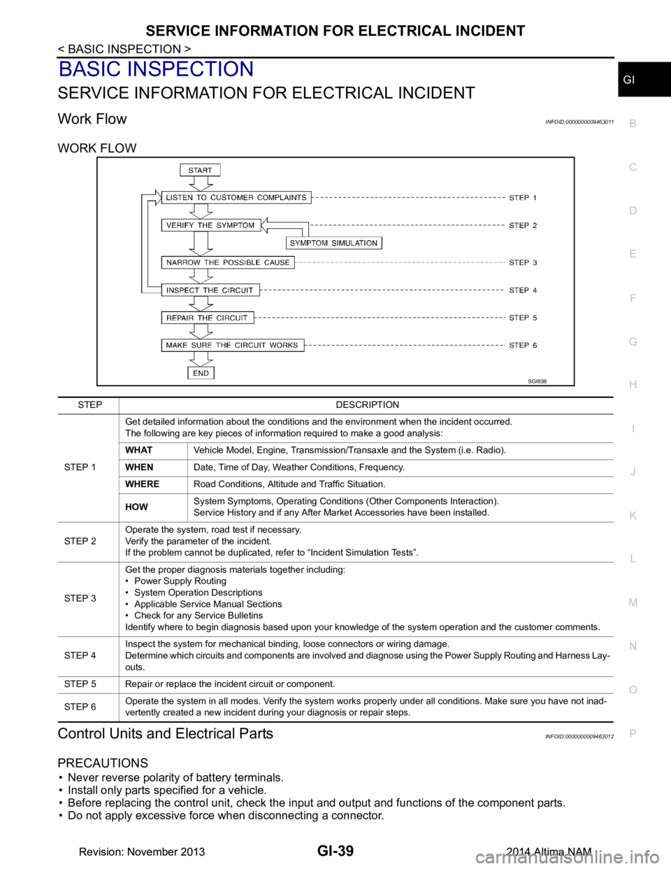
SERVICE INFORMATION FOR ELECTRICAL INCIDENTGI-39
< BASIC INSPECTION >
C
D E
F
G H
I
J
K L
M B
GI
N
O PBASIC INSPECTION
SERVICE INFORMATION FO R ELECTRICAL INCIDENT
Work FlowINFOID:0000000009463011
WORK FLOW
Control Units and Electrical PartsINFOID:0000000009463012
PRECAUTIONS
• Never reverse polarity of battery terminals.
• Install only parts specified for a vehicle.
• Before replacing the control unit, check the i nput and output and functions of the component parts.
• Do not apply excessive force when disconnecting a connector.
SGI838
STEP DESCRIPTION
STEP 1 Get detailed information about the conditions and the environment when the incident occurred.
The following are key pieces of information required to make a good analysis:
WHAT Vehicle Model, Engine, Transmission/Transaxle and the System (i.e. Radio).
WHEN Date, Time of Day, Weather Conditions, Frequency.
WHERE Road Conditions, Altitude and Traffic Situation.
HOW System Symptoms, Operating Conditions (Other Components Interaction).
Service History and if any After Market Accessories have been installed.
STEP 2 Operate the system, road test if necessary.
Verify the parameter of the incident.
If the problem cannot be duplicated, refer to “Incident Simulation Tests”.
STEP 3 Get the proper diagnosis materials together including:
• Power Supply Routing
• System Operation Descriptions
• Applicable Service Manual Sections
• Check for any Service Bulletins
Identify where to begin diagnosis based upon your knowledge of the system operation and the customer comments.
STEP 4 Inspect the system for mechanical binding, loose connectors or wiring damage.
Determine which circuits and components are involved and diagnose using the Power Supply Routing and Harness Lay-
outs.
STEP 5 Repair or replace the incident circuit or component.
STEP 6 Operate the system in all modes. Verify the system works properly under all conditions. Make sure you have not inad-
vertently created a new incident during your diagnosis or repair steps.
Revision: November 20132014 Altima NAMRevision: November 20132014 Altima NAM