seat adjustment NISSAN TEANA 2014 Service Manual
[x] Cancel search | Manufacturer: NISSAN, Model Year: 2014, Model line: TEANA, Model: NISSAN TEANA 2014Pages: 4801, PDF Size: 51.2 MB
Page 97 of 4801
BR-1
BRAKES
C
D E
G H
I
J
K L
M
SECTION BR
A
B
BR
N
O P
CONTENTS
BRAKE SYSTEM
PRECAUTION ................ ...............................3
PRECAUTIONS .............................................. .....3
Precaution for Supplemental Restraint System
(SRS) "AIR BAG" and "SEAT BELT PRE-TEN-
SIONER" ............................................................. ......
3
Precaution for Procedure without Cowl Top Cover ......3
Precaution for Brake System ....................................3
PREPARATION ............................................5
PREPARATION .............................................. .....5
Special Service Tool ........................................... ......5
Commercial Service Tool ..........................................5
SYSTEM DESCRIPTION ..............................6
NOISE, VIBRATION AND HARSHNESS
(NVH) TROUBLESHOOTING ........................ .....
6
NVH Troubleshooting Chart ................................ ......6
BASIC INSPECTION ....................................7
BRAKE PEDAL .............................................. .....7
Inspection ............................................................ ......7
BRAKE FLUID .....................................................8
Inspection ............................................................ ......8
BRAKE MASTER CYLINDER ........................ .....9
Inspection ............................................................ ......9
On Board Inspection .................................................9
BRAKE BOOSTER ............................................10
Inspection ............................................................ ....10
FRONT DISC BRAKE .................................... ....11
BRAKE PAD .......................................................... ....11
BRAKE PAD : Inspection ........................................11
DISC ROTOR ......................................................... ....11
DISC ROTOR : Inspection ......................................11
REAR DISC BRAKE .........................................12
BRAKE PAD .......................................................... ....12
BRAKE PAD : Inspection .........................................12
DISC ROTOR ......................................................... ....12
DISC ROTOR : Inspection .......................................12
PERIODIC MAINTENANCE ........................13
BRAKE PEDAL ................................ .................13
Inspection and Adjustment .................................. ....13
BRAKE FLUID ................................. .................14
Drain and Refill .................................................... ....14
Bleeding Brake System ...........................................14
FRONT DISC BRAKE .......................................16
Brake Burnishing ................................................. ....16
REAR DISC BRAKE .........................................17
Brake Burnishing ................................................. ....17
REMOVAL AND INSTALLATION ...............18
BRAKE PEDAL ................................ .................18
Exploded View ..................................................... ....18
Removal and Installation .........................................18
BRAKE PIPING ................................ .................20
FRONT ................................................................... ....20
FRONT : Exploded View .........................................20
FRONT : Hydraulic Piping .......................................21
FRONT : Removal and Installation ..........................21
REAR ..................................................................... ....23
REAR : Exploded View ............................................23
REAR : Hydraulic Piping ..........................................24
REAR : Removal and Installation ............................24
BRAKE MASTER CYLINDER ..........................26
Exploded View .........................................................26
Removal and Installation .........................................26
Revision: November 20132014 Altima NAM
Page 147 of 4801

BRC-1
BRAKES
C
D E
G H
I
J
K L
M
SECTION BRC
A
B
BRC
N
O P
CONTENTS
BRAKE CONTROL SYSTEM
VDC/TCS/ABS
PRECAUTION ................ ...............................
4
PRECAUTIONS .............................................. .....4
Precaution for Supplemental Restraint System
(SRS) "AIR BAG" and "SEAT BELT PRE-TEN-
SIONER" ............................................................. ......
4
Precaution for Brake System ....................................4
Precaution for Brake Control .....................................5
Precaution for CAN System ................................ ......5
Precaution for Work ..................................................6
PREPARATION ............................................7
PREPARATION .............................................. .....7
Special Service Tool ........................................... ......7
Commercial Service Tool ..........................................7
SYSTEM DESCRIPTION ..............................8
COMPONENT PARTS ................................... .....8
Component Parts Location .................................. ......8
Component Description .............................................9
ABS Actuator and Electric Unit (Control Unit) ...........9
Wheel Sensor and Sensor Rotor ............................10
Stop Lamp Switch ...................................................10
Steering Angle Sensor ............................................10
Brake Fluid Level Switch .........................................10
Vacuum Sensor .......................................................10
Parking Brake Switch ..............................................11
VDC OFF Switch .....................................................11
SYSTEM .............................................................12
VDC/TCS/ABS ....................................................... ....12
VDC/TCS/ABS : System Diagram ...........................12
VDC/TCS/ABS : System De scription ......................12
VDC/TCS/ABS : VDC Functi on ...............................23
VDC/TCS/ABS : TCS Functi on ...............................25
VDC/TCS/ABS : ABS Function ........................... ....27
VDC/TCS/ABS : EBD Functi on ...............................28
VDC/TCS/ABS : Fail-safe ... .....................................29
DIAGNOSIS SYSTEM [ABS ACTUATOR
AND ELECTRIC UNIT (CONTROL UNIT)] .......
33
CONSULT Function (ABS) .................................. ....33
ECU DIAGNOSIS INFORMATION ..............38
ABS ACTUATOR AND ELECTRIC UNIT
(CONTROL UNIT) .............................................
38
Reference Value .................................................. ....38
Fail-safe ...................................................................41
DTC Inspection Priority Chart ..................................44
DTC Index ...............................................................45
WIRING DIAGRAM ......................................47
BRAKE CONTROL SYSTEM ...........................47
Wiring Diagram .................................................... ....47
BASIC INSPECTION ...................................55
DIAGNOSIS AND REPAIR WORK FLOW .......55
Work Flow ............................................................ ....55
Diagnostic Work Sheet ............................................56
ADDITIONAL SERVICE WHEN REPLACING
ABS ACTUATOR AND ELECTRIC UNIT
(CONTROL UNIT) .............................................
57
Description ........................................................... ....57
ADJUSTMENT OF STEERING ANGLE SEN-
SOR NEUTRAL POSITION ...............................
58
Description ........................................................... ....58
Work Procedure .......................................................58
CONFIGURATION [ABS ACTUATOR AND
ELECTRIC UNIT (CONTROL UNIT)] ................
60
Work Procedure ................................................... ....60
CALIBRATION OF DECEL G SENSOR ...........62
Description ...............................................................62
Revision: November 20132014 Altima NAMRevision: November 20132014 Altima NAM
Page 773 of 4801
DLK-5
C
D E
F
G H
I
J
L
M A
B
DLK
N
O P
REAR DOOR LOCK ..............................................
..
204
REAR DOOR LOCK : Exploded View ...................204
REAR DOOR LOCK : Removal and Installation ...205
TRUNK LID ..................................................... ..206
TRUNK LID ASSEMBLY ...... ...................................206
TRUNK LID ASSEMBLY : Exploded View .......... ..206
TRUNK LID ASSEMBLY : Removal and Installa-
tion ...................................................................... ..
206
TRUNK LID ASSEMBLY : Adjustment ................ ..208
TRUNK LID HINGE ............................................... ..209
TRUNK LID HINGE : Removal and Installation ....209
TORSION BAR ...................................................... ..210
TORSION BAR : Removal and Installation ...........210
TRUNK LAMP SWITCH AND TRUNK RELEASE
SOLENOID ............................................................ ..
210
TRUNK LAMP SWITCH AND TRUNK RELEASE
SOLENOID : Removal and Installation .................
210
EMERGENCY LEVER ........................................... ..211
EMERGENCY LEVER : Removal and Installation ..211
TRUNK LID STRIKER ........................................... ..211
TRUNK LID STRIKER : Removal and Installation ..211
FUEL FILLER LID OPENER ............................213
Exploded View .................................................... ..213
FUEL FILLER LID ................................................. ..213
FUEL FILLER LID : Removal and Installation .......213
FUEL FILLER OPENER CABLE ........................... ..214
FUEL FILLER OPENER CABLE : Removal and
Installation ........................................................... ..
214
FUEL FILLER LID LOCK ...................................... ..215
FUEL FILLER LID LOCK : Removal and Installa-
tion ...................................................................... ..
215
KEY CYLINDER ...............................................217
GLOVE BOX LID KEY CYLINDER ....................... ..217
GLOVE BOX LID KEY CYLINDER : Removal and
Installation ........................................................... ..
217
SEATBACK LOCK KEY CYLINDER .................... ..218
SEATBACK LOCK KEY CYLINDER : Removal
and Installation .................................................... ..
218
DOOR SWITCH ................................................219
Removal and Installation .......................................219
INSIDE KEY ANTENNA ..................................220
CONSOLE .............................................................. ..220
CONSOLE : Removal and Installation ...................220
LUGGAGE ROOM ................................................. ..220
LUGGAGE ROOM : Removal and Installation ......220
OUTSIDE KEY ANTENNA ..............................221
DRIVER SIDE ......................................................... ..221
DRIVER SIDE : Removal and Installation .............221
PASSENGER SIDE ..................................................221
PASSENGER SIDE : Removal and Installation .. ..221
REAR BUMPER ..................................................... ..221
REAR BUMPER : Removal and Installation ..........221
DOOR REQUEST SWITCH ............................222
DRIVER SIDE ......................................................... ..222
DRIVER SIDE : Removal and Installation .............222
PASSENGER SIDE ..................................................222
PASSENGER SIDE : Removal and Installation .. ..222
INTELLIGENT KEY WARNING BUZZER .......223
Removal and Installation .......................................223
REMOTE KEYLESS ENTRY RECEIVER .......224
Removal and Installation .......................................224
INTELLIGENT KEY BATTERY .......................225
Removal and Installation .......................................225
TRUNK LID OPENER CANCEL SWITCH ......226
Removal and Installation .......................................226
TRUNK LID OPENER SWITCH ......................227
Removal and Installation .......................................227
TRUNK OPENER REQUEST SWITCH ..........228
Removal and Installation .......................................228
UNIT DISASSEMBLY AND ASSEMBLY ..229
FRONT DOOR .................................................229
Exploded View ..................................................... ..229
Disassembly and Assembly ...................................229
REAR DOOR ...................................................231
Exploded View .......................................................231
Disassembly and Assembly ...................................231
Revision: November 20132014 Altima NAMRevision: November 20132014 Altima NAM
Page 774 of 4801
DLK-6
< PRECAUTION >
PRECAUTIONS
PRECAUTION
PRECAUTIONS
Precaution for Supplemental Restraint System (SRS) "AIR BAG" and "SEAT BELT
PRE-TENSIONER"
INFOID:0000000009951560
The Supplemental Restraint System such as “A IR BAG” and “SEAT BELT PRE-TENSIONER”, used along
with a front seat belt, helps to reduce the risk or severi ty of injury to the driver and front passenger for certain
types of collision. Information necessary to service the system safely is included in the SR and SB section of
this Service Manual.
WARNING:
• To avoid rendering the SRS inopera tive, which could increase the risk of personal injury or death in
the event of a collision which would result in air bag inflation, all maintenance must be performed by
an authorized NISS AN/INFINITI dealer.
• Improper maintenance, including in correct removal and installation of the SRS, can lead to personal
injury caused by unintent ional activation of the system. For re moval of Spiral Cable and Air Bag
Module, see the SR section.
• Do not use electrical test equipmen t on any circuit related to the SRS unless instructed to in this
Service Manual. SRS wiring harn esses can be identified by yellow and/or orange harnesses or har-
ness connectors.
PRECAUTIONS WHEN USING POWER TOOLS (AIR OR ELECTRIC) AND HAMMERS
WARNING:
• When working near the Airbag Diagnosis Sensor Unit or other Airbag System sensors with the Igni-
tion ON or engine running, DO NOT use air or electri c power tools or strike near the sensor(s) with a
hammer. Heavy vibration could activate the sensor( s) and deploy the air bag(s), possibly causing
serious injury.
• When using air or electric power tools or hammers , always switch the Ignition OFF, disconnect the
battery and wait at least three minutes before performing any service.
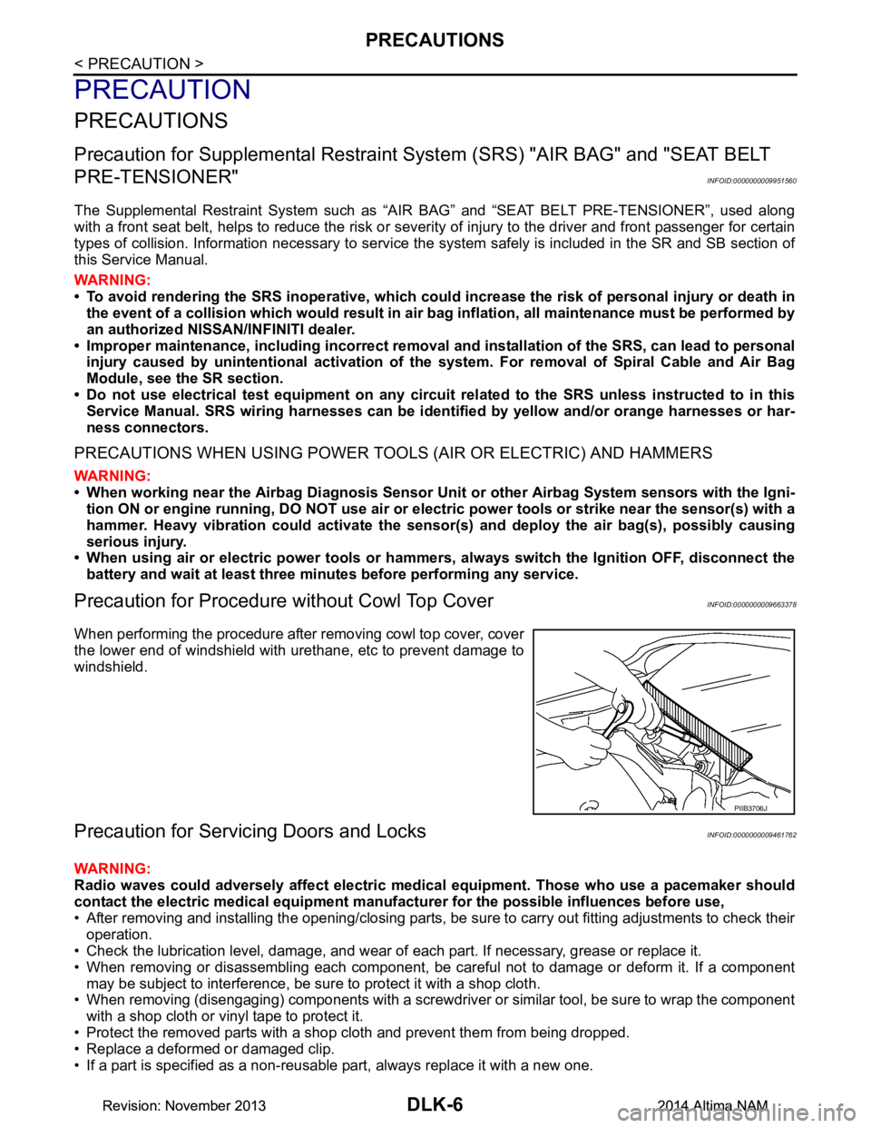
Precaution for Procedure without Cowl Top CoverINFOID:0000000009663378
When performing the procedure after removing cowl top cover, cover
the lower end of windshield with urethane, etc to prevent damage to
windshield.
Precaution for Servicing Doors and LocksINFOID:0000000009461762
WARNING:
Radio waves could adversely affect electric medical equipment. Those who use a pacemaker should
contact the electric medical eq uipment manufacturer for the possible influences before use,
• After removing and installing the opening/closing parts, be sure to carry out fitting adjustments to check their
operation.
• Check the lubrication level, damage, and wear of each part. If necessary, grease or replace it.
• When removing or disassembling each component, be careful not to damage or deform it. If a component may be subject to interference, be sure to protect it with a shop cloth.
• When removing (disengaging) components with a screwdriver or similar tool, be sure to wrap the component
with a shop cloth or vinyl tape to protect it.
• Protect the removed parts with a s hop cloth and prevent them from being dropped.
• Replace a deformed or damaged clip.
• If a part is specified as a non-reusable part, always replace it with a new one.
PIIB3706J
Revision: November 20132014 Altima NAMRevision: November 20132014 Altima NAM
Page 935 of 4801
SQUEAK AND RATTLE TROUBLE DIAGNOSESDLK-167
< SYMPTOM DIAGNOSIS >
C
D E
F
G H
I
J
L
M A
B
DLK
N
O P
3. Loose screws at console attachment points.
SEATS
When isolating seat noise it's important to note the pos ition the seat is in and the load placed on the seat when
the noise is present. These conditions should be duplic ated when verifying and isolating the cause of the
noise.
Cause of seat noise include:
1. Headrest rods and holder
2. A squeak between the seat pad cushion and frame
3. The rear seatback lock and bracket
These noises can be isolated by moving or pressing on the suspected components while duplicating the con-
ditions under which the noise occurs. Most of thes e incidents can be repaired by repositioning the component
or applying urethane tape to the contact area.
UNDERHOOD
Some interior noise may be caused by components under the hood or on the engine wall. The noise is then
transmitted into the passenger compartment.
Causes of transmitted underhood noise include:
1. Any component installed to the engine wall
2. Components that pass through the engine wall
3. Engine wall mounts and connectors
4. Loose radiator installation pins
5. Hood bumpers out of adjustment
6. Hood striker out of adjustment
These noises can be difficult to isolate since they cannot be reached from the interior of the vehicle. The best
method is to secure, move or insulate one component at a time and test drive the vehicle. Also, engine rpm or
load can be changed to isolate the noise. Repairs can usually be made by moving, adjusting, securing, or
insulating the component causing the noise.
Revision: November 20132014 Altima NAMRevision: November 20132014 Altima NAM
Page 945 of 4801
HOOD
DLK-177
< REMOVAL AND INSTALLATION >
C
D E
F
G H
I
J
L
M A
B
DLK
N
O P
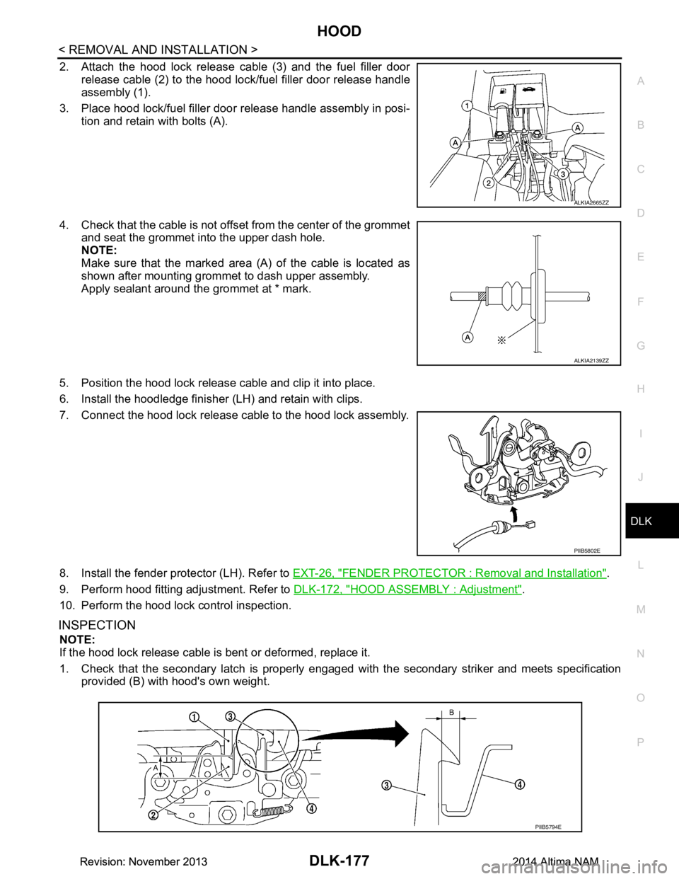
2. Attach the hood lock release cable (3) and the fuel filler door release cable (2) to the hood lock/fuel filler door release handle
assembly (1).
3. Place hood lock/fuel filler door release handle assembly in posi- tion and retain with bolts (A).
4. Check that the cable is not offset from the center of the grommet
and seat the grommet into the upper dash hole.
NOTE:
Make sure that the marked area (A) of the cable is located as
shown after mounting grommet to dash upper assembly.
Apply sealant around the grommet at * mark.
5. Position the hood lock release cable and clip it into place.
6. Install the hoodledge finisher (LH) and retain with clips.
7. Connect the hood lock release cable to the hood lock assembly.
8. Install the fender protector (LH). Refer to EXT-26, "FENDER PROTECTOR : Removal and Installation"
.
9. Perform hood fitting adjustment. Refer to DLK-172, "HOOD ASSEMBLY : Adjustment"
.
10. Perform the hood lock control inspection.
INSPECTION
NOTE:
If the hood lock release cable is bent or deformed, replace it.
1. Check that the secondary latch is properly engaged wi th the secondary striker and meets specification
provided (B) with hood's own weight.
ALKIA2665ZZ
ALKIA2139ZZ
PIIB5802E
PIIB5794E
Revision: November 20132014 Altima NAMRevision: November 20132014 Altima NAM
Page 982 of 4801
DLK-214
< REMOVAL AND INSTALLATION >
FUEL FILLER LID OPENER
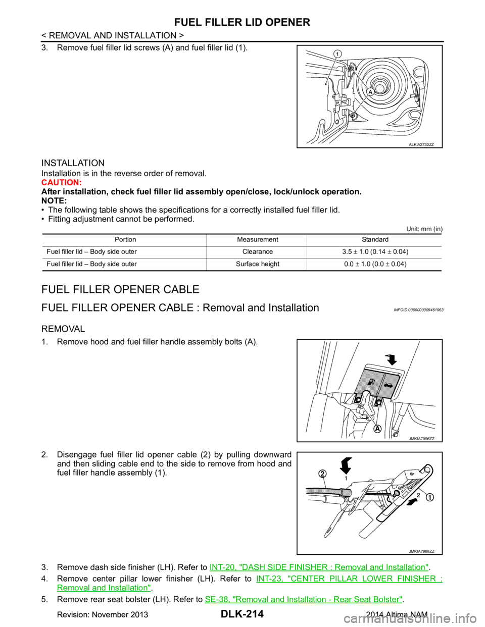
3. Remove fuel filler lid screws (A) and fuel filler lid (1).
INSTALLATION
Installation is in the reverse order of removal.
CAUTION:
After installation, check fuel filler li d assembly open/close, lock/unlock operation.
NOTE:
• The following table shows the specifications for a correctly installed fuel filler lid.
• Fitting adjustment cannot be performed.
Unit: mm (in)
FUEL FILLER OP ENER CABLE
FUEL FILLER OPENER CABLE : Removal and InstallationINFOID:0000000009461963
REMOVAL
1. Remove hood and fuel filler handle assembly bolts (A).
2. Disengage fuel filler lid opener cable (2) by pulling downward and then sliding cable end to the side to remove from hood and
fuel filler handle assembly (1).
3. Remove dash side finisher (LH). Refer to INT-20, "DASH SIDE FINISHER : Removal and Installation"
.
4. Remove center pillar lower finisher (LH). Refer to INT-23, "CENTER PILLAR LOWER FINISHER :
Removal and Installation".
5. Remove rear seat bolster (LH). Refer to SE-38, "Removal and Installation - Rear Seat Bolster"
.
ALKIA2732ZZ
Portion Measurement Standard
Fuel filler lid – Body side outer Clearance 3.5 ± 1.0 (0.14 ± 0.04)
Fuel filler lid – Body side outer Surface height 0.0 ± 1.0 (0.0 ± 0.04)
JMKIA7998ZZ
JMKIA7999ZZ
Revision: November 20132014 Altima NAMRevision: November 20132014 Altima NAM
Page 1999 of 4801
EM-1
ENGINE
C
D E
F
G H
I
J
K L
M
SECTION EM
A
EM
N
O P
CONTENTS
ENGINE MECHANICAL
QR25DE
PRECAUTION ................ ...............................
4
PRECAUTIONS .............................................. .....4
Precaution for Supplemental Restraint System
(SRS) "AIR BAG" and "SEAT BELT PRE-TEN-
SIONER" ............................................................. ......
4
Precaution for Draining Coolant ................................4
Precaution for Disconnecting Fuel Piping .................4
Precaution for Removal and Disassembly ................4
Precaution for Inspection, Repair and Replace-
ment .................................................................... ......
4
Special Cautions to Ensure the Safe Disposal of
Sodium-filled Exhaust Valves .............................. ......
5
Precaution for Assembly and Installation ..................6
Parts Requiring Angular Tightening ..........................6
Precaution for Liquid Gasket ............................... ......6
PREPARATION ............................................8
PREPARATION .............................................. .....8
Special Service Tool ........................................... ......8
Commercial Service Tool ........................................10
SYMPTOM DIAGNOSIS ..............................13
NOISE, VIBRATION, AND HARSHNESS
(NVH) TROUBLESHOOTING ........................ ....
13
NVH Troubleshooting - Engine Noise ................. ....13
Use the Chart Below to Help You Find the Cause
of the Symptom ................................................... ....
14
PERIODIC MAINTENANCE .........................16
SPARK PLUG .. .............................................. ....16
Exploded View .................................................... ....16
Removal and Installation .........................................16
DRIVE BELTS ................................................ ....19
Exploded View .................................................... ....19
Checking Drive Belts ...............................................19
Tension Adjustment ............................................. ....19
Removal and Installation .........................................19
Removal and Installation of Drive Belt Auto-ten-
sioner ................................................................... ....
20
AIR CLEANER FILTER .....................................22
Exploded View .........................................................22
Removal and Installation .........................................22
CAMSHAFT VALVE CLEARANCE ..................23
Camshaft valve clearance .......................................23
COMPRESSION PRESSURE ...........................26
Compression pressure ............................................26
REMOVAL AND INSTALLATION ...............28
ENGINE ROOM COVER ...................................28
Exploded View ..................................................... ....28
Removal and Installation .........................................28
AIR CLEANER AND AIR DUCT .......................29
Exploded View .........................................................29
Removal and Installation .........................................29
INTAKE MANIFOLD .........................................30
Exploded View .........................................................30
Removal and Installation .........................................30
EXHAUST MANIFOLD AND THREE WAY
CATALYST ........................................................
33
Exploded View ..................................................... ....33
Removal and Installation .........................................33
OIL PAN AND OIL STRAINER .........................36
Exploded View .........................................................36
Removal and Installation .........................................36
IGNITION COIL .................................................40
Exploded View .........................................................40
Removal and Installation .........................................40
FUEL INJECTOR AND FUEL TUBE ................41
Revision: November 20132014 Altima NAM
Page 2000 of 4801

EM-2
Exploded View ........................................................41
Removal and Installation ........................................41
ROCKER COVER ..............................................45
Exploded View ..................................................... ...45
Removal and Installation ........................................45
CAMSHAFT .......................................................47
Exploded View ..................................................... ...47
Removal and Installation ........................................47
Inspection After Installation ................................. ...56
VALVE TIMING CONTROL ............................ ...58
Exploded View ..................................................... ...58
Intake Valve Timing Intermediate Lock Control
Solenoid Valve, Intake Va lve Timing Control Sole-
noid Valve, and Exhaust Valve Timing Control So-
lenoid Valve ......................................................... ...
58
Valve Timing Control Cover ....................................59
TIMING CHAIN ............................................... ...61
Exploded View ..................................................... ...61
Removal and Installation ........................................62
OIL SEAL ...........................................................70
Removal and Installation of Valve Oil Seal .......... ...70
Removal and Installation of Front Oil Seal .............71
Removal and Installation of Rear Oil Seal ..............72
CYLINDER HEAD ..............................................74
Exploded View ..................................................... ...74
Removal and Installation ........................................74
Disassembly and Assembly ....................................76
Inspection After Disassembly .................................78
UNIT REMOVAL AND INSTALLATION .. ...83
ENGINE ASSEMBLY ...................................... ...83
Exploded View ..................................................... ...83
Removal and Installation ........................................84
UNIT DISASSEMBLY AND ASSEMBLY ....87
CYLINDER BLOCK ........................................ ...87
Exploded View ..................................................... ...87
Disassembly and Assembly ....................................88
Inspection After Disassembly .................................96
HOW TO SELECT PISTON AND BEARING .. .105
How to Select Piston and Bearing ....................... ..105
SERVICE DATA AND SPECIFICATIONS
(SDS) .............. ............................................
111
SERVICE DATA AND SPECIFICATIONS
(SDS) ............................................................... .
111
Standard and Limit .............................................. ..111
VQ35DE
PRECAUTION .............. ..............................
123
PRECAUTIONS .............................................. .123
Precaution for Supplemental Restraint System
(SRS) "AIR BAG" and "SEAT BELT PRE-TEN-
SIONER" .............................................................. .
123
Precaution for Draining Coolant ............................123
Precaution for Disconnecting Fuel Piping .............123
Precaution for Removal and Disassembly ............123
Precaution for Inspection, Repair and Replace-
ment ..................................................................... .
123
Precaution for Assembly and Installation ..............123
Parts Requiring Angular Tightening ..................... .124
Precaution for Liquid Gasket .................................124
PREPARATION .........................................126
PREPARATION .............................................. ..126
Special Service Tool ............................................ .126
Commercial Service Tool ......................................127
SYSTEM DESCRIPTION ..........................130
NOISE, VIBRATION, AND HARSHNESS
(NVH) TROUBLESHOOTING ......................... ..
130
NVH Troubleshooting - Engine Noise .................. .130
Use the Chart Below to Help You Find the Cause
of the Symptom .................................................... .
131
PERIODIC MAINTENANCE ......................132
SPARK PLUG ... .............................................. ..132
Exploded View ..................................................... .132
Removal and Installation .......................................132
DRIVE BELTS ................................................ ..134
Exploded View ..................................................... .134
Checking Drive Belts .............................................134
Tension Adjustment ..............................................134
Removal and Installation .......................................134
Removal and Installation of Drive Belt Auto-ten-
sioner ................................................................... .
135
AIR CLEANER FILTER ....................................137
Exploded View ..................................................... .137
Removal and Installation .......................................137
CAMSHAFT VALVE CLEARANCE ............... ..138
Valve Clearance ................................................... .138
COMPRESSION PRESSURE ..........................142
On-Vehicle Service .............................................. .142
REMOVAL AND INSTALLATION .............143
ENGINE ROOM COVER ................................ ..143
Exploded View ..................................................... .143
Removal and Installation .......................................143
AIR CLEANER AND AIR DUCT ..................... ..144
Exploded View ..................................................... .144
Removal and Installation .......................................144
INTAKE MANIFOLD COLLECTOR ............... ..146
Exploded View ..................................................... .146
Revision: November 20132014 Altima NAM
Page 2388 of 4801
EXL-122
< PERIODIC MAINTENANCE >
HEADLAMP
PERIODIC MAINTENANCE
HEADLAMP
Aiming AdjustmentINFOID:0000000009463617
PREPARATION BEFORE ADJUSTING
Before performing aiming adjustment, check the following:
• Ensure all tires are inflated to correct pressure.
• Place vehicle and screen on level surface.
• Ensure there is no load in vehicle other than the driver (or equivalent weight placed in driver's position).
• Coolant and engine oil filled to correct level, and fuel tank full.
• Remove cargo and/or luggage to maintain an unloaded vehicle condition.
• Confirm spare tire, jack and tools are properly stowed.
• Carefully wipe off any dirt from headlamp lens. CAUTION:
Do not use organic solvent (thinner, gasoline etc.)
• Place a driver or equivalent weight of 68.5 kg (150 lb) on the driver seat.
• By hand, bounce the front and rear of the vehicle to settle the suspension and eliminate any static load.
• Place the front tires in the straight ahead position.
• Aim each headlamp individually and ensure other headlamp beam pattern is blocked from screen.
NOTE:
• For headlamp aiming details, refer to regulations in your area.
• By regulation, no means for horizontal aim adjustment is provided from the factory; only vertical aim is
adjustable.
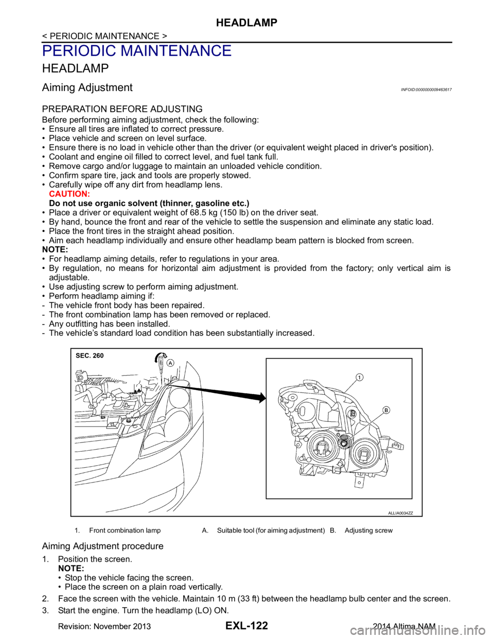
• Use adjusting screw to perform aiming adjustment.
• Perform headlamp aiming if:
- The vehicle front body has been repaired.
- The front combination lamp has been removed or replaced.
- Any outfitting has been installed.
- The vehicle’s standard load condition has been substantially increased.
Aiming Adjustment procedure
1. Position the screen.
NOTE:
• Stop the vehicle facing the screen.
• Place the screen on a plain road vertically.
2. Face the screen with the vehicle. Maintain 10 m (33 ft) between the headlamp bulb center and the screen.
3. Start the engine. Turn the headlamp (LO) ON.
1. Front combination lamp A. Suitable tool (for aiming adjustment) B. Adjusting screw
ALLIA0034ZZ
Revision: November 20132014 Altima NAMRevision: November 20132014 Altima NAM