stop NISSAN TEANA 2014 Service Manual
[x] Cancel search | Manufacturer: NISSAN, Model Year: 2014, Model line: TEANA, Model: NISSAN TEANA 2014Pages: 4801, PDF Size: 51.2 MB
Page 9 of 4801
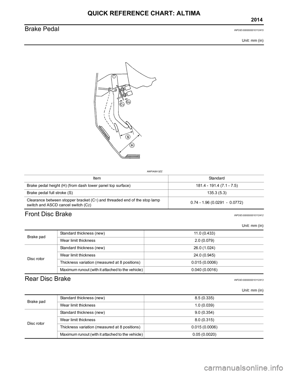
QUICK REFERENCE CHART: ALTIMA
2014
Brake PedalINFOID:0000000010112415
Unit: mm (in)
Front Disc BrakeINFOID:0000000010112412
Unit: mm (in)
Rear Disc BrakeINFOID:0000000010112413
Unit: mm (in)
ItemStandard
Brake pedal height (H) (from dash lower panel top surface) 181.4 - 191.4 (7.1 - 7.5)
Brake pedal full stroke (S) 135.3 (5.3)
Clearance between stopper bracket (C
1) and threaded end of the stop lamp
switch and ASCD cancel switch (C
2) 0.74 - 1.96 (0.0291 - 0.0772)
AWFIA0913ZZ
Brake padStandard thickness (new) 11.0 (0.433)
Wear limit thickness
2.0 (0.079)
Disc rotor Standard thickness (new)
26.0 (1.024)
Wear limit thickness 24.0 (0.945)
Thickness variation (measured at 8 positions) 0.015 (0.0006)
Maximum runout (with it attached to the vehicle) 0.040 (0.0016)
Brake padStandard thickness (new) 8.5 (0.335)
Wear limit thickness
1.0 (0.039)
Disc rotor Standard thickness (new)
9.0 (0.354)
Wear limit thickness 8.0 (0.315)
Thickness variation (measured at 8 positions) 0.015 (0.0006)
Maximum runout (with it attached to the vehicle) 0.05 (0.0020)
Page 27 of 4801
![NISSAN TEANA 2014 Service Manual
BCS-12
< SYSTEM DESCRIPTION >[BCM]
SYSTEM
SIGNAL BUFFER SYSTEM : System Description
INFOID:0000000009461993
OUTLINE
BCM has the signal transmission function that output s/transmits each input/receive](/img/5/57390/w960_57390-26.png "NISSAN TEANA 2014 Service Manual
BCS-12
< SYSTEM DESCRIPTION >[BCM]
SYSTEM
SIGNAL BUFFER SYSTEM : System Description
INFOID:0000000009461993
OUTLINE
BCM has the signal transmission function that output s/transmits each input/receive")
BCS-12
< SYSTEM DESCRIPTION >[BCM]
SYSTEM
SIGNAL BUFFER SYSTEM : System Description
INFOID:0000000009461993
OUTLINE
BCM has the signal transmission function that output s/transmits each input/received signal to each unit.
Signal transmission function list
POWER CONSUMPTION CONTROL SYSTEM
POWER CONSUMPTION CONTROL SYSTEM : System DiagramINFOID:0000000009461994
POWER CONSUMPTION CONTROL SY STEM : System DescriptionINFOID:0000000009461995
OUTLINE
• BCM incorporates a power saving control function t hat reduces the power consumption according to the
vehicle status.
• BCM switches the status (control mode) by itself wit h the power saving control function. It performs the sleep
request to each unit (IPDM E/R and combination mete r) that operates with the ignition switch OFF.
Normal mode (wake-up)
- CAN communication is normally performed with other units
- Each control with BCM is operating properly
CAN communication sleep mode (CAN sleep)
- CAN transmission is stopped
- Control with BCM only is operating
Low power consumption mode (BCM sleep)- Low power consumption control is active
- CAN transmission is stopped
LOW POWER CONSUMPTION CONTROL WITH BCM
BCM reduces the power consumption with the follo wing operation in the low power consumption mode.
• The reading interval of each switch changes from 10 ms interval to 60 ms interval.
Sleep mode activation
Signal name Input Output Description
• Ignition switch ON signal
• Ignition switch signal Engine switch (push switch) IPDM E/R (CAN) Inputs the push-button ignition
switch (push switch) signal and
transmits the ignition switch sta-
tus judged with BCM via CAN
communication.
Door switch signal Any door switch • Combination meter (CAN)
• IPDM E/R (CAN) Inputs the door switch signal
and transmits it via CAN com-
munication.
ALCIA0030GB
Revision: November 20132014 Altima NAMRevision: November 20132014 Altima NAM
Page 28 of 4801
![NISSAN TEANA 2014 Service Manual
BCS
SYSTEMBCS-13
< SYSTEM DESCRIPTION > [BCM]
C
D E
F
G H
I
J
K L
B
A
O P
N
• BCM receives the sleep-ready signal (ready) from IPDM E/R and combination meter via CAN communica-
tion.
• BCM tran](/img/5/57390/w960_57390-27.png "NISSAN TEANA 2014 Service Manual
BCS
SYSTEMBCS-13
< SYSTEM DESCRIPTION > [BCM]
C
D E
F
G H
I
J
K L
B
A
O P
N
• BCM receives the sleep-ready signal (ready) from IPDM E/R and combination meter via CAN communica-
tion.
• BCM tran")
BCS
SYSTEMBCS-13
< SYSTEM DESCRIPTION > [BCM]
C
D E
F
G H
I
J
K L
B
A
O P
N
• BCM receives the sleep-ready signal (ready) from IPDM E/R and combination meter via CAN communica-
tion.
• BCM transmits the sleep wake up signal (sleep) to each unit when all of the CAN sleep conditions are ful-
filled.
• Each unit stops the transmission of CAN communication with the sleep wakeup signal. BCM is in CAN com- munication sleep mode.
• BCM is in the low power consumption mode and performs the low power consumption control when all of the
BCM sleep conditions are fulfilled with CAN sleep condition.
Sleep condition
Wake-up operation
• BCM changes from the low power consumption m ode to the CAN communication sleep mode when the any
of the BCM wake-up conditions are fulfilled. Only the control with BCM is activated.
• BCM transmits the sleep wake up signal (wake up) to each unit when any of the CAN wake-up conditions are fulfilled. It changes from the low power consum ption mode or the CAN communication sleep mode to the
normal mode.
• Each unit starts the transmission of CAN communicati on with the sleep wake up signal. In addition, the com-
bination meter transmits the wake up signal to BCM via CAN communication to report the CAN communica-
tion start.
CAN sleep condition BCM sleep condition
• Receiving the sleep-ready signal (ready) from all units
• Ignition switch: OFF
• Vehicle security system alarm and panic alarm : No operation
• Warning lamp: Not operation
• Intelligent Key system buzzer: No operation
• Brake switch: OFF
• Turn signal indicator lamp: No operation
• Exterior lamp: OFF
• Door lock status: No change
• CONSULT communication status: No communication
• Meter display signal : Non-transmission
• Door switch status: No change
• Rear window defogger: OFF • Interior room lamp batte
ry saver: Time out
• RAP system: OFF
• Power window switch communication: No transmission
• Push-button ignition switch (push switch) illumination: OFF
• NATS: No operation
• Remote keyless entry receiver communication status: No
communication
• Tire pressure monitoring system: Stop
BCM wake-up condition CAN wake-up condition
• Door unlock sensor: OFF →ON, ON →OFF
• Door lock assembly LH (key cylinder switch): Lock or unlock
• Door lock switch: OFF →ON
• Door unlock switch: OFF →ON
• Trunk opener switch: OFF →ON
• Power window serial link communication: Receiving
• Remote keyless entry receiver: Receiving valid keyfob • Receiving the sleep-ready signal (Not-ready) from any units
• Push-button ignition switch (push switch): OFF →ON
• Hazard switch: OFF →ON
• PASSING switch: OFF →ON, ON →OFF
• TAIL LAMP switch: OFF →ON
• Driver door switch: OFF →ON, ON →OFF
• Passenger door switch: OFF → ON, ON → OFF
• Trunk switch: OFF →ON, ON →OFF
• Driver door request swit ch (if equipped): OFF→ON
• Passenger door request switch (if equipped): OFF →ON
• Stop lamp switch 2 signal: ON
• Remote keyless entry receiver: Receiving valid keyfob
Revision: November 20132014 Altima NAMRevision: November 20132014 Altima NAM
Page 34 of 4801
![NISSAN TEANA 2014 Service Manual
BCS
DIAGNOSIS SYSTEM (BCM)BCS-19
< SYSTEM DESCRIPTION > [BCM]
C
D E
F
G H
I
J
K L
B
A
O P
N
*: Initial setting
HEADLAMP
HEADLAMP : CONSULT Function (BCM - HEADLAMP)INFOID:0000000009462002
CAUTION:](/img/5/57390/w960_57390-33.png "NISSAN TEANA 2014 Service Manual
BCS
DIAGNOSIS SYSTEM (BCM)BCS-19
< SYSTEM DESCRIPTION > [BCM]
C
D E
F
G H
I
J
K L
B
A
O P
N
*: Initial setting
HEADLAMP
HEADLAMP : CONSULT Function (BCM - HEADLAMP)INFOID:0000000009462002
CAUTION:")
BCS
DIAGNOSIS SYSTEM (BCM)BCS-19
< SYSTEM DESCRIPTION > [BCM]
C
D E
F
G H
I
J
K L
B
A
O P
N
*: Initial setting
HEADLAMP
HEADLAMP : CONSULT Function (BCM - HEADLAMP)INFOID:0000000009462002
CAUTION:
After disconnecting the CONSULT vehicle interface (VI) from the data link connector, the ignition must
be cycled OFF → ON (for at least 5 seconds) → OFF. If this step is not performed, the BCM may not go
to ”sleep mode”, potentiall y causing a discharged battery and a no-start condition.
DATA MONITOR
Support Item Setting Description
DOOR LOCK-UNLOCK SET On* Automatic door locks function ON.
Off Automatic door locks function OFF.
HORN CHIRP SET Off
Horn chirp function can be changed in this mode.
On*
HAZARD LAMP SET MODE4* Lock and Unlock
Hazard warning lamp function can be changed in this mode.
MODE3 Lock Only
MODE2 Unlock Only
MODE1 OFF
AUTO LOCK SET MODE3 1 min
Auto locking function can be changed in this mode.
MODE2 OFF
MODE1* 5 min
PANIC ALRM SET MODE3 1.5 sec
Panic alarm operation can be changed in this mode.
MODE2 OFF
MODE1* 0.5 sec
PW DOWN SET MODE3 5 sec
Keyfob power window down can be changed in this mode.
MODE2 OFF
MODE1* 3 sec
Monitor Item [Unit] Description
PUSH SW [On/Off] Indicates condition of push-button ignition switch.
ENGINE STATE [STOP/STALL/CRANK/RUN] Indicates engine status received from ECM on CAN communication line.
VEH SPEED 1 [km/h] Indicates vehicle speed signal received from ABS on CAN communication line.
TURN SIGNAL R [On/Off]
Indicates condition of combination switch.
TURN SIGNAL L [On/Off]
TAIL LAMP SW [On/Off]
HI BEAM SW [On/Off]
HEAD LAMP SW 1 [On/Off]
HEAD LAMP SW 2 [On/Off]
PASSING SW [On/Off]
AUTO LIGHT SW [On/Off]
FR FOG SW [On/Off]
DOOR SW-DR [On/Off] Indicates condition of front door switch LH.
DOOR SW-AS [On/Off] Indicates condition of front door switch RH.
DOOR SW-RR [On/Off] Indicates condition of rear door switch RH.
DOOR SW-RL [On/Off] Indicates condition of rear door switch LH.
Revision: November 20132014 Altima NAMRevision: November 20132014 Altima NAM
Page 36 of 4801
![NISSAN TEANA 2014 Service Manual
BCS
DIAGNOSIS SYSTEM (BCM)BCS-21
< SYSTEM DESCRIPTION > [BCM]
C
D E
F
G H
I
J
K L
B
A
O P
N
ACTIVE TEST
WORK SUPPORT
* : Initial setting
FLASHER
FLASHER : CONSULT Func tion (BCM - FLASHER)INFOID:0](/img/5/57390/w960_57390-35.png "NISSAN TEANA 2014 Service Manual
BCS
DIAGNOSIS SYSTEM (BCM)BCS-21
< SYSTEM DESCRIPTION > [BCM]
C
D E
F
G H
I
J
K L
B
A
O P
N
ACTIVE TEST
WORK SUPPORT
* : Initial setting
FLASHER
FLASHER : CONSULT Func tion (BCM - FLASHER)INFOID:0")
BCS
DIAGNOSIS SYSTEM (BCM)BCS-21
< SYSTEM DESCRIPTION > [BCM]
C
D E
F
G H
I
J
K L
B
A
O P
N
ACTIVE TEST
WORK SUPPORT
* : Initial setting
FLASHER
FLASHER : CONSULT Func tion (BCM - FLASHER)INFOID:0000000009462004
CAUTION:
After disconnecting the CONSULT vehicle interface (VI) from the data link connector, the ignition must
be cycled OFF → ON (for at least 5 seconds) → OFF. If this step is not performed, the BCM may not go
to ”sleep mode”, potentiall y causing a discharged battery and a no-start condition.
DATA MONITOR
ACTIVE TEST
AIR CONDITIONER
AIR CONDITIONER : CONSULT Func tion (BCM - AIR CONDITIONER)INFOID:0000000009462005
CAUTION:
FR WIPER HI [On/Off]
Indicates condition of wiper operation of combination switch.
FR WIPER LOW [On/Off]
FR WASHER SW [On/Off]
FR WIPER INT [On/Off]
FR WIPER STOP [On/Off] Indicates front wiper auto stop signal received from IPDM E/R on CAN communication
line.
INT VOLUME [1 − 7] Indicates condition of intermittent wiper operation of combination switch.
Monitor Item [Unit] Description
Test Item Description
FR WIPER This test is able to check front wiper operation [Hi/Lo/INT/Off].
Support Item Setting Description
WIPER SPEED SETTING On Front wiper intermittent time linked with vehicle speed and wiper dial position.
Off* Front wiper intermittent time linked with wiper dial position.
Monitor Item [Unit] Description
REQ SW -DR [On/Off] Indicates condition of door request switch LH.
REQ SW -AS [On/Off] Indicates condition of door request switch RH.
PUSH SW [On/Off] Indicates condition of push-button ignition switch.
TURN SIGNAL R [On/Off] Indicates condition of turn signal function of combination switch.
TURN SIGNAL L [On/Off]
HAZARD SW [On/Off] Indicates condition of hazard switch.
RKE-LOCK [On/Off] Indicates condition of lock signal from Intelligent Key.
RKE-UNLOCK [On/Off] Indicates condition of unock signal from Intelligent Key.
RKE-PANIC [On/Off] Indicates condition of panic alarm signal from Intelligent Key.
Test Item Description
FLASHER This test is able to check turn signal lamp operation [Off/LH/RH].
Revision: November 20132014 Altima NAMRevision: November 20132014 Altima NAM
Page 37 of 4801
![NISSAN TEANA 2014 Service Manual
BCS-22
< SYSTEM DESCRIPTION >[BCM]
DIAGNOSIS SYSTEM (BCM)
After disconnecting the CONSULT vehicle interface (VI)
from the data link connector, the ignition must
be cycled OFF → ON (for at least 5](/img/5/57390/w960_57390-36.png "NISSAN TEANA 2014 Service Manual
BCS-22
< SYSTEM DESCRIPTION >[BCM]
DIAGNOSIS SYSTEM (BCM)
After disconnecting the CONSULT vehicle interface (VI)
from the data link connector, the ignition must
be cycled OFF → ON (for at least 5")
BCS-22
< SYSTEM DESCRIPTION >[BCM]
DIAGNOSIS SYSTEM (BCM)
After disconnecting the CONSULT vehicle interface (VI)
from the data link connector, the ignition must
be cycled OFF → ON (for at least 5 seconds) → OFF. If this step is not performed, the BCM may not go
to ”sleep mode”, potentially causing a di scharged battery and a no-start condition.
DATA MONITOR
INTELLIGENT KEY
INTELLIGENT KEY : CONSULT Function (BCM - INTELLIGENT KEY)INFOID:0000000009462006
CAUTION:
After disconnecting the CONSULT vehicle interface (VI) from the data link connector, the ignition must
be cycled OFF → ON (for at least 5 seconds) → OFF. If this step is not performed, the BCM may not go
to ”sleep mode”, potentially causing a di scharged battery and a no-start condition.
SELF DIAGNOSTIC RESULT
Refer to BCS-52, "DTC Index".
DATA MONITOR
Monitor Item [Unit] Description
FAN ON SIG [On/Off] Indicates condition of fan switch.
AIR COND SW [On/Off] Indicates condition of A/C switch.
Monitor Item [Unit] Main Description
REQ SW -DR [On/Off] ×Indicates condition of door request switch LH.
REQ SW -AS [On/Off] ×Indicates condition of door request switch RH.
REQ SW -BD/TR [On/Off] ×Indicates condition of trunk opener request switch.
PUSH SW [On/Off] Indicates condition of push-button ignition switch.
SHFTLCK SLNID PER SPLY [On/Off] ×Indicates condition of power supply to shiftlock solenoid.
BRAKE SW 1 [On/Off] ×Indicates condition of brake switch.
BRAKE SW 2 [On/Off] Indicates condition of brake switch.
DETE/CANCL SW [On/Off] ×Indicates condition of P (park) position.
SFT PN/N SW [On/Off] ×Indicates condition of P (park) or N (neutral) position.
UNLK SEN -DR [On/Off] ×Indicates condition of door unlock sensor.
PUSH SW -IPDM [On/Off] Indicates condition of push-button ignition switch received from IPDM E/R
on CAN communication line.
IGN RLY1 -F/B [On/Off] Indicates condition of ignition relay 1 received from IPDM E/R on CAN
communication line.
DETE SW -IPDM [On/Off] Indicates condition of detent switch received from TCM on CAN communi-
cation line.
SFT PN -IPDM [On/Off] Indicates condition of P (park) or N (neutral) position from TCM on CAN
communication line.
SFT P -MET [On/Off] Indicates condition of P (park) position from TCM on CAN communication
line.
SFT N -MET [On/Off] Indicates condition of N (neutral) position from IPDM E/R on CAN commu-
nication line.
ENGINE STATE [STOP/START/CRANK/RUN] ×Indicates condition of engine state from ECM on CAN communication line.
VEH SPEED 1 [mph/km/h] ×Indicates condition of vehicle speed signal received from ABS on CAN
communication line.
VEH SPEED 2 [mph/km/h] ×Indicates condition of vehicle speed signal received from combination
meter on CAN communication line.
DOOR STAT -DR [LOCK/READY/UNLK] ×Indicates condition of driver side door status.
Revision: November 20132014 Altima NAMRevision: November 20132014 Altima NAM
Page 38 of 4801
![NISSAN TEANA 2014 Service Manual
BCS
DIAGNOSIS SYSTEM (BCM)BCS-23
< SYSTEM DESCRIPTION > [BCM]
C
D E
F
G H
I
J
K L
B
A
O P
N
ACTIVE TEST
DOOR STAT -AS [LOCK/READY/UNLK]
×Indicates condition of passenger side door status.
DOOR STA](/img/5/57390/w960_57390-37.png "NISSAN TEANA 2014 Service Manual
BCS
DIAGNOSIS SYSTEM (BCM)BCS-23
< SYSTEM DESCRIPTION > [BCM]
C
D E
F
G H
I
J
K L
B
A
O P
N
ACTIVE TEST
DOOR STAT -AS [LOCK/READY/UNLK]
×Indicates condition of passenger side door status.
DOOR STA")
BCS
DIAGNOSIS SYSTEM (BCM)BCS-23
< SYSTEM DESCRIPTION > [BCM]
C
D E
F
G H
I
J
K L
B
A
O P
N
ACTIVE TEST
DOOR STAT -AS [LOCK/READY/UNLK]
×Indicates condition of passenger side door status.
DOOR STAT -RR [LOCK/READY/UNLK] ×Indicates condition of rear right side door status.
DOOR STAT -RL [LOCK/READY/UNLK] ×Indicates condition of rear left side door status.
ID OK FLAG [Set/Reset] Indicates condition of Intelligent Key ID.
PRMT ENG STRT [Set/Reset] Indicates condition of engine start possibility.
PRMT RKE STRT [Set/Reset] Indicates condition of engine start possibility from Intelligent Key.
I-KEY OK FLAG [Key ON/Key OFF] ×Indicates condition of Intelligent Key OK flag.
PRBT ENG STRT [Set/Reset] Indicates condition of engine start prohibit.
ID AUTHENT CANCEL TIMER [STOP] Indicates condition of Intelligent Key ID authentication.
ACC BATTERY SAVER [STOP] Indicate s condition of battery saver.
CRNK PRBT TMR [On/Off] In dicates condition of crank prohibit timer.
AUT CRNK TMR [On/Off] Indicates condition of automatic engine crank timer from Intelligent Key.
CRNK PRBT TME [sec] I ndicates condition of engine crank prohibit time.
AUTO CRNK TME [sec] Indicates co ndition of automatic engine crank time from Intelligent Key.
CRANKING TME [sec] Indicates condition of engine cranking time from Intelligent Key.
DETE SW PWR [On/Off] Indicates condition of detent switch voltage.
ACC RLY -REQ [On/Off] Indicates condition of accessory relay control request.
RKE OPE COUN1 [0-19] ×When remote keyless entry receiver receives the signal transmitted while
operating on Intelligent Key, the numerical value start changing.
RKE OPE COUN2 [0-19] ×When remote keyless entry receiver receives the signal transmitted while
operating on Intelligent Key, the numerical value start changing.
TRNK/HAT MNTR [On/Off] Indicates condition of trunk room lamp switch.
RKE-LOCK [On/Off] Indicates condition of lock signal from Intelligent Key.
RKE-UNLOCK [On/Off] Indicates condition of unlock signal from Intelligent Key.
RKE-TR/BD [On/Off] Indicates condition of trunk open signal from Intelligent Key.
RKE-PANIC [On/Off] Indicates condition of panic signal from Intelligent Key.
RKE-MODE CHG [On/Off] Indicates condition of mode change signal from Intelligent Key. Monitor Item [Unit] Main Description
Test Item Description
INTELLIGENT KEY LINK (CAN) This test is able to check Intelligent Key iden
tification number [Off/ID No1/ID N02/ID No3/ID
No4/ID No5].
INT LAMP This test is able to check interior room lamp operation [On/Off].
FLASHER This test is able to check hazard lamp operation [LH/RH/Off].
HORN This test is able to check horn operation [On].
BATTERY SAVER This test is able to check battery saver operation [On/Off].
TRUNK/BACK DOOR This test is able to check trunk actuator operation [Open].
OUTSIDE BUZZER This test is able to check In telligent Key warning buzzer operation [On/Off].
INSIDE BUZZER This test is able to check combination meter warning chime operation [Take Out/Knob/Key/
Off].
INDICATOR This test is able to check combination meter warning lamp operation [KEY ON/KEY IND/Off].
IGN CONT2 This test is able to check ignition relay-2 control operation [On/Off].
ENGINE SW ILLUMI This test is able to check push-bu tton ignition switch START indicator operation [On/Off].
PUSH SWITCH INDICATOR This test is able to check push-button ignition switch indicator operation [On/Off].
ACC CONT This test is able to check ac cessory relay control operation [On/Off].
IGN CONT1 This test is able to check ignition relay-1 control operation [On/Off].
Revision: November 20132014 Altima NAMRevision: November 20132014 Altima NAM
Page 46 of 4801
![NISSAN TEANA 2014 Service Manual
BCS
BCM (BODY CONTROL MODULE)BCS-31
< ECU DIAGNOSIS INFORMATION > [BCM]
C
D E
F
G H
I
J
K L
B
A
O P
N
ECU DIAGNOSIS INFORMATION
BCM (BODY CONTROL MODULE)
Reference ValueINFOID:0000000009462016
NOTE](/img/5/57390/w960_57390-45.png "NISSAN TEANA 2014 Service Manual
BCS
BCM (BODY CONTROL MODULE)BCS-31
< ECU DIAGNOSIS INFORMATION > [BCM]
C
D E
F
G H
I
J
K L
B
A
O P
N
ECU DIAGNOSIS INFORMATION
BCM (BODY CONTROL MODULE)
Reference ValueINFOID:0000000009462016
NOTE")
BCS
BCM (BODY CONTROL MODULE)BCS-31
< ECU DIAGNOSIS INFORMATION > [BCM]
C
D E
F
G H
I
J
K L
B
A
O P
N
ECU DIAGNOSIS INFORMATION
BCM (BODY CONTROL MODULE)
Reference ValueINFOID:0000000009462016
NOTE:
The Signal Tech II Tool (J-50190) can be used to perform the following functions. Refer to the Signal Tech II
User Guide for additional information.
• Activate and display TPMS transmitter IDs
• Display tire pressure repor ted by the TPMS transmitter
• Read TPMS DTCs
• Register TPMS transmitter IDs
• Check Intelligent Key relative signal strength
• Confirm vehicle Intelligent Key antenna signal strength
VALUES ON THE DIAGNOSIS TOOL
Monitor Item Condition Value/Status
ACC BATTERY SAVER When battery saver is OFF. STOP
ACC RLY -REQ When BCM is not requesting accessory relay activation. Off
When BCM is requesting accessory relay activation. On
AIR COND SW A/C switch OFF Off
A/C switch ON On
AIR PRESS FL Front left tire air pressure value kPa, kg/cm
2, psi
AIR PRESS FR Front right tire air pressure value kPa, kg/cm
2, psi
AIR PRESS RL Rear left ti re air pressure value
kPa, kg/cm
2, psi
AIR PRESS RR Rear right ti re air pressure value
kPa, kg/cm
2, psi
AUTO CRNK TME Remote engine start timer duration. sec
AUTO CRNK TMR When the remote engine start timer is OFF. Off
When the remote engine start timer is ON. On
AUTO LIGHT SW Lighting switch OFF Off
Lighting switch AUTO On
BRAKE SW 1 When the brake pedal is released On
When the brake pedal is depressed Off
BRAKE SW2 Brake pedal released Off
Brake pedal depressed On
BUZZER Buzzer in combination meter OFF Off
Buzzer in combination meter ON On
CDL LOCK SW Door lock/unlock switch does not operate Off
Press door lock/unlock switch to the LOCK side On
CDL UNLOCK SW Door lock/unlock switch does not operate Off
Press door lock/unlock switch to the UNLOCK side On
CONFRM ID ALL The key ID does not match any key ID registered to BCM. Yet
The key ID matches any key ID registered to BCM. DONE
CONFIRM ID4 The key ID does not match the fourth key ID registered to BCM. Yet
The key ID matches the fourth key ID registered to BCM. DONE
CONFIRM ID3 The key ID does not match the third key ID registered to BCM. Yet
The key ID matches the third key ID registered to BCM. DONE
Revision: November 20132014 Altima NAMRevision: November 20132014 Altima NAM
Page 47 of 4801
![NISSAN TEANA 2014 Service Manual
BCS-32
< ECU DIAGNOSIS INFORMATION >[BCM]
BCM (BODY CONTROL MODULE)
CONFIRM ID2The key ID does not match the second key ID registered to BCM. Yet
The key ID matches the second key ID registered to B](/img/5/57390/w960_57390-46.png "NISSAN TEANA 2014 Service Manual
BCS-32
< ECU DIAGNOSIS INFORMATION >[BCM]
BCM (BODY CONTROL MODULE)
CONFIRM ID2The key ID does not match the second key ID registered to BCM. Yet
The key ID matches the second key ID registered to B")
BCS-32
< ECU DIAGNOSIS INFORMATION >[BCM]
BCM (BODY CONTROL MODULE)
CONFIRM ID2The key ID does not match the second key ID registered to BCM. Yet
The key ID matches the second key ID registered to BCM. DONE
CONFIRM ID1 The key ID does not match the first key ID registered to BCM. Yet
The key ID matches the first key ID registered to BCM. DONE
CRANKING TME Engine start timer duration. sec
CRNK PRBT TME Engine start prohibit timer duration. sec
CRNK PRBT TMR When the engine start prohibit timer is OFF. Off
When the engine start prohibit timer is ON. On
DETE SW -IPDM When selector lever is in P position Off
When selector lever is in any position other than P On
DETE SW PWR When BCM is not supplying power to detent switch. Off
When BCM is supplying power to detent switch. On
DETE/CANCL SW When selector lever is in P position Off
When selector lever is in any position other than P On
DOOR STAT-AS Passenger door LOCK status LOCK
Passenger door UNLOCK status UNLK
Wait with selective UNLOCK operation (5 seconds) READY
DOOR STAT-DR Driver door LOCK status LOCK
Driver door UNLOCK status UNLK
Wait with selective UNLOCK operation (5 seconds) READY
DOOR STAT-RL Rear left door LOCK status LOCK
Rear left door UNLOCK status UNLK
Wait with selective UNLOCK operation (5 seconds) READY
DOOR STAT-RR Rear right door LOCK status LOCK
Rear right door UNLOCK status UNLK
Wait with selective UNLOCK operation (5 seconds) READY
DOOR SW-AS Front door RH closed Off
Front door RH opened On
DOOR SW-BK Trunk closed Off
Trunk opened On
DOOR SW-DR Front door LH closed Off
Front door LH opened On
DOOR SW-RL Rear door LH closed Off
Rear door LH opened On
DOOR SW-RR Rear door RH closed Off
Rear door RH opened On
ENGINE STATE Engine stopped STOP
While the engine stalls STALL
At engine cranking CRANK
Engine running RUN
FA N O N S I G Blower motor fan switch OFF Off
Blower motor fan switch ON On
FR FOG SW Front fog lamp switch OFF Off
Front fog lamp switch ON On
Monitor Item Condition Value/Status
Revision: November 20132014 Altima NAMRevision: November 20132014 Altima NAM
Page 48 of 4801
![NISSAN TEANA 2014 Service Manual
BCS
BCM (BODY CONTROL MODULE)BCS-33
< ECU DIAGNOSIS INFORMATION > [BCM]
C
D E
F
G H
I
J
K L
B
A
O P
N
FR WASHER SW
Front washer switch OFF Off
Front washer switch ON On
FR WIPER LOW Front wiper sw](/img/5/57390/w960_57390-47.png "NISSAN TEANA 2014 Service Manual
BCS
BCM (BODY CONTROL MODULE)BCS-33
< ECU DIAGNOSIS INFORMATION > [BCM]
C
D E
F
G H
I
J
K L
B
A
O P
N
FR WASHER SW
Front washer switch OFF Off
Front washer switch ON On
FR WIPER LOW Front wiper sw")
BCS
BCM (BODY CONTROL MODULE)BCS-33
< ECU DIAGNOSIS INFORMATION > [BCM]
C
D E
F
G H
I
J
K L
B
A
O P
N
FR WASHER SW
Front washer switch OFF Off
Front washer switch ON On
FR WIPER LOW Front wiper switch OFF Off
Front wiper switch LO On
FR WIPER HI Front wiper switch OFF Off
Front wiper switch HI On
FR WIPER INT Front wiper switch OFF Off
Front wiper switch INT On
FR WIPER STOP Any position other than front wiper stop position Off
Front wiper stop position On
HAZARD SW When hazard switch is not pressed Off
When hazard switch is pressed On
HEAD LAMP SW 1 Headlamp switch OFF Off
Headlamp switch 1st On
HEAD LAMP SW 2 Headlamp switch OFF Off
Headlamp switch 1st On
HI BEAM SW High beam switch OFF Off
High beam switch HI On
ID AUTHENT CANCEL TIMER When I-Key authentication is OFF. STOP
ID OK FLAG Ignition switch ACC or ON Reset
Ignition switch OFF Set
ID REGST FL1 ID registration of front left tire incomplete YET
ID registration of front left tire complete DONE
ID REGST FR1 ID registration of front right tire incomplete YET
ID registration of front right tire complete DONE
ID REGST RL1 ID registration of rear left tire incomplete YET
ID registration of rear left tire complete DONE
ID REGST RR1 ID registration of rear
right tire incomplete YET
ID registration of rear right tire complete DONE
IGN RLY1 F/B Ignition switch OFF or ACC Off
Ignition switch ON On
INT VOLUME Wiper intermittent dial is in a dial position 1 - 7 1 - 7
I-KEY OK FLAG I-Key OFF Key OFF
I-Key ON Key ON
KEY CYL LK-SW Door key cylinder LOCK position Off
Door key cylinder other than LOCK position On
KEY CYL UN-SW Door key cylinder UNLOCK position Off
Door key cylinder other than UNLOCK position On
OPTI SEN (DTCT) Bright outside of the vehicle Close to 5V
Dark outside of the vehicle Close to 0V
OPTI SEN (FILT) Bright outside of the vehicle Close to 5V
Dark outside of the vehicle Close to 0V
PA S S I N G S W Other than lighting switch PASS Off
Lighting switch PASS On
Monitor Item Condition Value/Status
Revision: November 20132014 Altima NAMRevision: November 20132014 Altima NAM