tow bar NISSAN TEANA 2014 Service Manual
[x] Cancel search | Manufacturer: NISSAN, Model Year: 2014, Model line: TEANA, Model: NISSAN TEANA 2014Pages: 4801, PDF Size: 51.2 MB
Page 125 of 4801

BRAKE BOOSTERBR-29
< REMOVAL AND INSTALLATION >
C
D E
G H
I
J
K L
M A
B
BR
N
O P
5. Remove the snap pin (1) and clevis pin (2) from the brake pedal. CAUTION:
Do not reuse snap pin or clevis pin.
6. Disconnect the harness connectors from the ASCD cancel switch and stop lamp switch.
7. Disconnect the steering column assembly pinch bolt and position the steering column shaft aside. Refer to
ST-33, "Exploded View"
.
8. Remove the brake master cylinder. Refer to BR-26, "Removal and Installation"
.
9. Disconnect the fuel line main connections. Refer to FL-5, "Quick Connector"
.
10. Remove the cowl top. Refer to EXT-24, "Removal and Installation"
.
11. Remove the strut tower bar. Refer to FSU-19, "Exploded View"
.
12. Remove the wiper drive assembly. Refer to WW-64, "Removal and Installation"
.
13. Remove the cowl top extension.
14. Disconnect the vacuum hose from the brake booster.
15. Disconnect the active boost sensor harness connector.
16. Remove brake booster nuts.
17. Remove the brake booster.
18. Remove and discard the brake booster gasket. CAUTION:
Do not reuse brake booster gasket.
INSTALLATION
Installation is in the reverse order of removal.
• Prior to installation, loosen clevis lock nut (1) and adjust input rod (2) to the specified value (B).
• After input rod adjustment (B), temporarily tighten clevis lock nut for installation of brake booster.
• Connect the battery negative terminal. Refer to PG-7, "ADDITIONAL SERVICE WHEN REMOVING BAT-
TERY NEGATIVE TERMINAL : Special Repair Requirement".
Removal and Installation - VQ35DEINFOID:0000000009463708
CAUTION:
• Do not deform or bend brake tube while removing and installing brake booster.
• Do not reuse snap pin or clevis pin.
• Do not reuse brake booster gasket.
• Do not damage brake booster stud bolt threads. If brake booster is tilted during service, the dash
panel may damage the threads.
REMOVAL
1. Release the fuel pressure from the fuel system. Refer to EC-687, "Work Procedure".
JPFIA0019ZZ
Length (B) : Refer to BR-49, "Brake Booster".
ALFIA0299ZZ
Revision: November 20132014 Altima NAM
Page 126 of 4801

BR-30
< REMOVAL AND INSTALLATION >
BRAKE BOOSTER
2. Disconnect the battery negative cable. Refer to PG-73, "Removal and Installation (Battery)".
3. Remove the instrument lower panel LH. Refer to IP-21, "Removal and Installation"
.
4. Remove accelerator pedal assembly. Refer to ACC-3, "Removal and Installation"
.
5. Remove the brake pedal. Refer to BR-18, "Removal and Installation"
.
6. Loosen the clevis lock nut (A) and remove the clevis bracket (B) from the input rod (C).
7. Remove the brake master cylinder. Refer to BR-26, "Removal and Installation"
.
8. Remove the vacuum hose. Refer to BR-31, "Exploded View"
.
9. Disconnect the fuel line main connections. Refer to FL-5, "Quick Connector"
.
10. Remove the cowl top. Refer to EXT-24, "Removal and Installation"
.
11. Remove the strut tower bar. Refer to FSU-19, "Exploded View"
.
12. Remove the wiper drive assembly. Refer to WW-64, "Removal and Installation"
.
13. Remove the cowl top extension.
14. Disconnect the active boost sensor harness connector.
15. Remove the brake booster.
16. Remove and discard the brake booster gasket. CAUTION:
Do not reuse brake booster gasket.
INSTALLATION
Installation is in the reverse order of removal.
• Prior to installation, loosen clevis lock nut (1) and adjust input rod (2) to the specified value (B).
• After input rod adjustment (B), temporarily tighten clevis lock nut for installation of brake booster.
• Connect the battery negative terminal. Refer to PG-7, "ADDITIONAL SERVICE WHEN REMOVING BAT-
TERY NEGATIVE TERMINAL : Special Repair Requirement".
:Front
ALFIA0319ZZ
Length (B) : Refer to BR-49, "Brake Booster".
ALFIA0299ZZ
Revision: November 20132014 Altima NAM
Page 151 of 4801
![NISSAN TEANA 2014 Service Manual
PRECAUTIONSBRC-5
< PRECAUTION > [VDC/TCS/ABS]
C
D E
G H
I
J
K L
M A
B
BRC
N
O P
Precaution for Brake ControlINFOID:0000000009463736
• During ABS operation, the brake pedal may vibrate lightly and NISSAN TEANA 2014 Service Manual
PRECAUTIONSBRC-5
< PRECAUTION > [VDC/TCS/ABS]
C
D E
G H
I
J
K L
M A
B
BRC
N
O P
Precaution for Brake ControlINFOID:0000000009463736
• During ABS operation, the brake pedal may vibrate lightly and](/img/5/57390/w960_57390-150.png)
PRECAUTIONSBRC-5
< PRECAUTION > [VDC/TCS/ABS]
C
D E
G H
I
J
K L
M A
B
BRC
N
O P
Precaution for Brake ControlINFOID:0000000009463736
• During ABS operation, the brake pedal may vibrate lightly and a mechanical noise may be heard. This is normal.
• Just after starting vehicle, the brake pedal may vibrate or a motor operating noise may be heard from engine
compartment. This is a normal status of operation check.
• Stopping distance may be longer than that of vehicles without ABS when vehicle drives on rough, gravel, or
snow-covered (fresh, deep snow) roads.
• When an error is indicated by ABS or another warning lamp, collect all necessary information from customer
(what symptoms are present under what conditions) and check for simple causes before starting diagnosis.
Besides electrical system inspection, check boos ter operation, brake fluid level, and fluid leaks.
• If incorrect tire sizes or types are installed on the vehicle or brake pads are not Genuine NISSAN parts, stop-
ping distance or steering stability may deteriorate.
• If there is a radio, antenna or related wiring near control module, ABS function may have a malfunction or
error.
• If aftermarket parts (car stereo, CD player, etc.) have been installed, check for incidents such as harness pinches, open circuits or improper wiring.
• If the following components are replaced with non-genuine components or modified, the VDC OFF indicator
lamp and SLIP indicator lamp may turn on or the VDC system may not operate properly. Components
related to suspension (shock absorbers, struts, springs , bushings, etc.), tires, wheels (exclude specified
size), components related to brake system (pads, roto rs, calipers, etc.), components related to engine (muf-
fler, ECM, etc.), components related to body reinforcement (roll bar, tower bar, etc.).
• Driving with broken or excessively worn suspensi on components, tires or brake system components may
cause the VDC OFF indicator lamp and the SLIP indicator lamp to turn on, and the VDC system may not
operate properly.
• When the TCS or VDC is activated by sudden acceleration or sudden turn, some noise may occur. The
noise is a result of the normal operation of the TCS and VDC.
• When driving on roads which have extreme slopes (such as mountainous roads) or high banks (such as sharp curves on a freeway), the VDC may not operate no rmally, or the VDC warning lamp and the SLIP indi-
cator lamp may turn on. This is not a problem if normal operation can be resumed after restarting the engine.
• Sudden turns (such as spin turns, acceleration turns), drifting, etc. with VDC turned off may cause the yaw rate/side/decel G sensor to indicate a problem. This is not a problem if normal operation can be resumed
after restarting the engine.
Precaution for CAN SystemINFOID:0000000009463737
• Do not apply voltage of 7.0V or higher to terminal to be measured.
• Maximum open terminal voltage of tester in use must be less than 7.0V.
• Before checking harnesses, turn ignition switch OFF and disconnect battery negative cable.
• Area to be repaired must be soldered and wrapped with tape. Make sure that fraying of twisted wire is within 110 mm (4.33 in).
PKIA0306E
Revision: November 20132014 Altima NAMRevision: November 20132014 Altima NAM
Page 969 of 4801

DOOR HANDLEDLK-201
< REMOVAL AND INSTALLATION >
C
D E
F
G H
I
J
L
M A
B
DLK
N
O P
CAUTION:
• Check rear door lock cables are properly engaged to inside handle.
• After installation, check rear doo r open/close, lock/unlock operation.
REAR DOOR HANDLE : Removal and Installation - Outside HandleINFOID:0000000009461948
REMOVAL
1. Fully close rear door glass.
2. Remove rear door finisher. Refer to INT-18, "Removal and Installation"
.
3. Remove rear door vapor barrier.
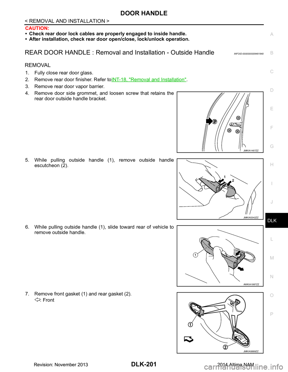
4. Remove door side grommet, and loosen screw that retains the rear door outside handle bracket.
5. While pulling outside handle (1), remove outside handle escutcheon (2).
6. While pulling outside handle (1), slide toward rear of vehicle to remove outside handle.
7. Remove front gasket (1) and rear gasket (2). : Front
JMKIA1467ZZ
JMKIA5342ZZ
AWKIA1997ZZ
JMKIA5889ZZ
Revision: November 20132014 Altima NAMRevision: November 20132014 Altima NAM
Page 2028 of 4801
![NISSAN TEANA 2014 Service Manual
EM-30
< REMOVAL AND INSTALLATION >[QR25DE]
INTAKE MANIFOLD
INTAKE MANIFOLD
Exploded ViewINFOID:0000000009460480
Removal and InstallationINFOID:0000000009460481
REMOVAL
WARNING:
To avoid the danger o NISSAN TEANA 2014 Service Manual
EM-30
< REMOVAL AND INSTALLATION >[QR25DE]
INTAKE MANIFOLD
INTAKE MANIFOLD
Exploded ViewINFOID:0000000009460480
Removal and InstallationINFOID:0000000009460481
REMOVAL
WARNING:
To avoid the danger o](/img/5/57390/w960_57390-2027.png)
EM-30
< REMOVAL AND INSTALLATION >[QR25DE]
INTAKE MANIFOLD
INTAKE MANIFOLD
Exploded ViewINFOID:0000000009460480
Removal and InstallationINFOID:0000000009460481
REMOVAL
WARNING:
To avoid the danger of being scalded, never drain the coolant when the engine is hot.
NOTE:
When removing components such as hoses, tubes/lines, etc. , cap or plug openings to prevent fluid from spill-
ing.
1. Disconnect battery negative terminal. Refer to PG-73, "Removal and Installation (Battery)"
.
2. Release the fuel pressure. Refer to EC-182, "Work Procedure"
.
3. Partially drain engine coolant. Refer to CO-12, "Changing Engine Coolant"
.
4. Remove the air cleaner and air duct. Refer to EM-29, "Removal and Installation"
.
5. Remove cowl top finisher. Refer to EXT-24, "Removal and Installation"
.
6. Remove strut tower bar. Refer to FSU-19, "Exploded View"
.
7. Disconnect the PCV hose from the intake manifold.
8. Disconnect the EVAP hose and EVAP canister purge volume control solenoid.
1. Electric throttle control actuator 2. Map sensor (California only) 3. Map hose (California only)
4. Clamp 5. Cap (except California) 6. Intake manifold gasket
7. Intake manifold 8. Electric throttle control actuator O-ringA. Refer to INSTALLATION
B. Refer to INSTALLATION C. Refer to INSTALLATION
AWBIA1768ZZ
Revision: November 20132014 Altima NAM
Page 2144 of 4801
![NISSAN TEANA 2014 Service Manual
EM-146
< REMOVAL AND INSTALLATION >[VQ35DE]
INTAKE MANIFOLD COLLECTOR
INTAKE MANIFOLD COLLECTOR
Exploded ViewINFOID:0000000009460541
CAUTION:
Do not remove power valves.
Removal and InstallationINFO NISSAN TEANA 2014 Service Manual
EM-146
< REMOVAL AND INSTALLATION >[VQ35DE]
INTAKE MANIFOLD COLLECTOR
INTAKE MANIFOLD COLLECTOR
Exploded ViewINFOID:0000000009460541
CAUTION:
Do not remove power valves.
Removal and InstallationINFO](/img/5/57390/w960_57390-2143.png)
EM-146
< REMOVAL AND INSTALLATION >[VQ35DE]
INTAKE MANIFOLD COLLECTOR
INTAKE MANIFOLD COLLECTOR
Exploded ViewINFOID:0000000009460541
CAUTION:
Do not remove power valves.
Removal and InstallationINFOID:0000000009460542
REMOVAL
WARNING:
To avoid the danger of being scalded, do no t drain the coolant when the engine is hot.
1. Remove the cowl top. Refer to EXT-24, "Removal and Installation"
.
2. Remove the strut tower bar. Refer to FSU-19, "Exploded View"
.
3. Remove the engine room cover. Refer to EM-143, "Removal and Installation"
.
4. Remove front air duct and air duct hose and resonator assembly. Refer to EM-144, "Removal and Installa-
tion".
5. Partially drain the engine coolant. Refer to CO-36, "Changing Engine Coolant"
.
NOTE:
1. Intake manifold collector 2. Intake manifold collector gasket 3. Electric throttle control actuator gasket
4. Electric throttle control actuator A. Refer to INSTALLATION B. Refer to INSTALLATION
AWBIA1336ZZ
Revision: November 20132014 Altima NAM
Page 2161 of 4801
![NISSAN TEANA 2014 Service Manual
FUEL INJECTOR AND FUEL TUBEEM-163
< REMOVAL AND INSTALLATION > [VQ35DE]
C
D E
F
G H
I
J
K L
M A
EM
NP
O
FUEL INJECTOR AND FUEL TUBE
Exploded ViewINFOID:0000000009460554
CAUTION:
• Apply new engin NISSAN TEANA 2014 Service Manual
FUEL INJECTOR AND FUEL TUBEEM-163
< REMOVAL AND INSTALLATION > [VQ35DE]
C
D E
F
G H
I
J
K L
M A
EM
NP
O
FUEL INJECTOR AND FUEL TUBE
Exploded ViewINFOID:0000000009460554
CAUTION:
• Apply new engin](/img/5/57390/w960_57390-2160.png)
FUEL INJECTOR AND FUEL TUBEEM-163
< REMOVAL AND INSTALLATION > [VQ35DE]
C
D E
F
G H
I
J
K L
M A
EM
NP
O
FUEL INJECTOR AND FUEL TUBE
Exploded ViewINFOID:0000000009460554
CAUTION:
• Apply new engine oil when installi ng the parts as specified to do so.
• Do not remove or disassemble part s unless instructed as shown.
Removal and InstallationINFOID:0000000009460555
REMOVAL
WARNING:
• Put a “CAUTION: FLAMMABLE” sign in the workshop.
• Be sure to work in a well ventila ted area and furnish workshop with a CO
2 fire extinguisher.
• Do not smoke while servicing fuel system. Keep open flames and sparks away from the work area.
• To avoid the danger of being scalded, do no t drain engine coolant when engine is hot.
1. Remove engine room cover. Refer to EM-143, "Removal and Installation"
.
2. Release the fuel pressure. Refer to EC-687, "Work Procedure"
.
3. Disconnect the battery negative terminal. Refer to PG-73, "Removal and Installation (Battery)"
.
4. Remove front wiper arm and cowl top extension. Refer to EXT-24, "Removal and Installation"
.
5. Remove strut tower bar. Refer to FSU-19, "Exploded View"
.
AWBIA1351ZZ
1. Fuel feed hose 2. Quick connector cap 3. Fuel tube
4. O-ring 5. Fuel damper 6. Fuel damper cap
7. Clip 8. O-ring (black) 9. Fuel injector
10. O-ring (green) A. Refer to INSTALLATION
Revision: November 20132014 Altima NAM
Page 2510 of 4801

FRONT COIL SPRING AND STRUTFSU-9
< REMOVAL AND INSTALLATION >
C
D
F
G H
I
J
K L
M A
B
FSU
N
O P
REMOVAL AND INSTALLATION
FRONT COIL SPRING AND STRUT
Exploded ViewINFOID:0000000009460627
Removal and InstallationINFOID:0000000009460628
REMOVAL
1. Remove front wheel and tire using power tool. Refer to WT-53, "Inspection".
2. Remove brake hose lock plate and brake hose from front coil spring and strut.
3. Remove stabilizer bar connecting rod end from front coil spring and strut. Refer to FSU-19, "Exploded
View".
4. Remove wheel sensor harness from front coil spring and strut.
5. Remove front coil spring and strut to steering knuckle bolts.
6. Remove bolts on strut tower.
7. Remove front coil spring and strut from vehicle. • To disassemble the front coil spring and strut, refer to FSU-22, "Disassembly and Assembly"
.
INSTALLATION
Installation is in the reverse order of removal.
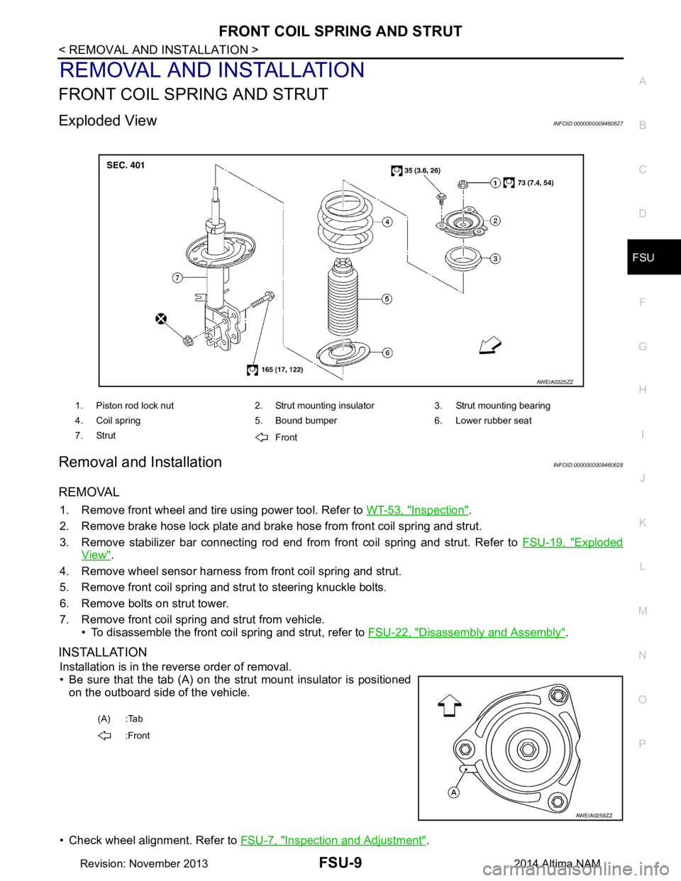
• Be sure that the tab (A) on the strut mount insulator is positioned on the outboard side of the vehicle.
• Check wheel alignment. Refer to FSU-7, "Inspection and Adjustment"
.
1. Piston rod lock nut 2. Strut mounting insulator 3. Strut mounting bearing
4. Coil spring 5. Bound bumper 6. Lower rubber seat
7. Strut Front
AWEIA0325ZZ
(A) :Tab
:Front
AWEIA0259ZZ
Revision: November 20132014 Altima NAM
Page 2521 of 4801

FSU-20
< UNIT REMOVAL AND INSTALLATION >
FRONT SUSPENSION ASSEMBLY
Removal and Installation
INFOID:0000000009460637
QR25DE ENGINE
Removal
1. Remove front wheel and tire using power tool. Refer to WT-55, "Adjustment".
2. Remove each brake caliper using power tool, leaving brake caliper hydraulic hose attached. Position each brake caliper aside with wire. Refer to BR-36, "BRAKE CALIPER ASSEMBLY : Exploded View"
.
CAUTION:
• Do not depress brake pedal while brake caliper is removed.
• Do not twist or stretch the brake hose.
3. Put alignment marks on each disc rotor and each wheel hub and bearing assembly.
4. Remove each disc rotor.
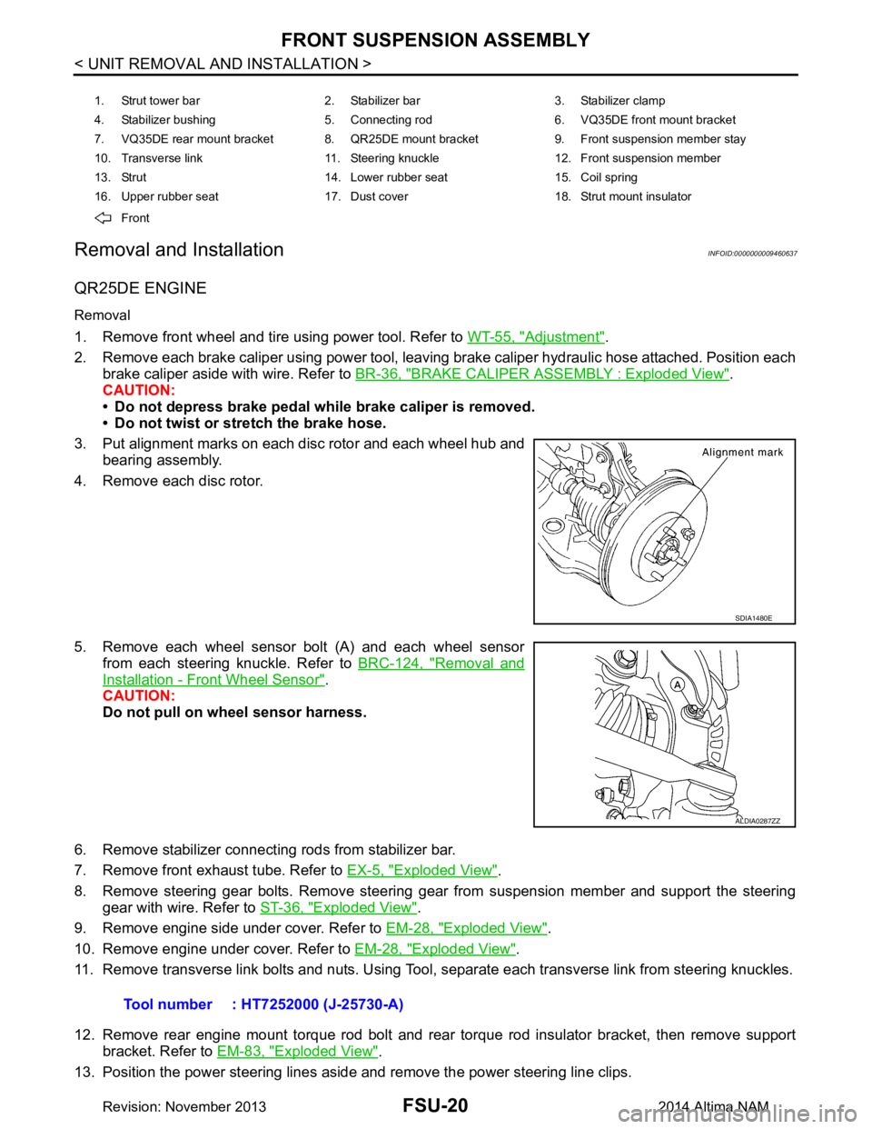
5. Remove each wheel sensor bolt (A) and each wheel sensor from each steering knuckle. Refer to BRC-124, "Removal and
Installation - Front Wheel Sensor".
CAUTION:
Do not pull on wheel sensor harness.
6. Remove stabilizer connecting rods from stabilizer bar.
7. Remove front exhaust tube. Refer to EX-5, "Exploded View"
.
8. Remove steering gear bolts. Remove steering gear from suspension member and support the steering gear with wire. Refer to ST-36, "Exploded View"
.
9. Remove engine side under cover. Refer to EM-28, "Exploded View"
.
10. Remove engine under cover. Refer to EM-28, "Exploded View"
.
11. Remove transverse link bolts and nuts. Using Tool, separate each transverse link from steering knuckles.
12. Remove rear engine mount torque rod bolt and rear torque rod insulator bracket, then remove support bracket. Refer to EM-83, "Exploded View"
.
13. Position the power steering lines aside and remove the power steering line clips.
1. Strut tower bar 2. Stabilizer bar 3. Stabilizer clamp
4. Stabilizer bushing 5. Connecting rod 6. VQ35DE front mount bracket
7. VQ35DE rear mount bracket 8. QR25DE mount bracket 9. Front suspension member stay
10. Transverse link 11. Steering knuckle 12. Front suspension member
13. Strut 14. Lower rubber seat 15. Coil spring
16. Upper rubber seat 17. Dust cover 18. Strut mount insulator
Front
SDIA1480E
ALDIA0287ZZ
Tool number : HT7252000 (J-25730-A)
Revision: November 20132014 Altima NAM
Page 2594 of 4801

GW-14
< REMOVAL AND INSTALLATION >
FRONT DOOR GLASS
FRONT DOOR GLASS
Removal and InstallationINFOID:0000000009463662
WARNING:
• Before servicing, turn ignition sw itch OFF, disconnect both battery terminals and wait at least three
minutes.
• Do not use air tools or el ectric tools for servicing.
REMOVAL
NOTE:
LH side shown; RH side similar
1. Disconnect the battery positive and negative terminal. Refer to PG-73, "Removal and Installation (Bat-
tery)".
2. Remove the front door finisher. Refer to INT-15, "Removal and Installation"
.
3. Remove the vapor barrier. CAUTION:
Use care to not damage or tear vapor barrier during removal.
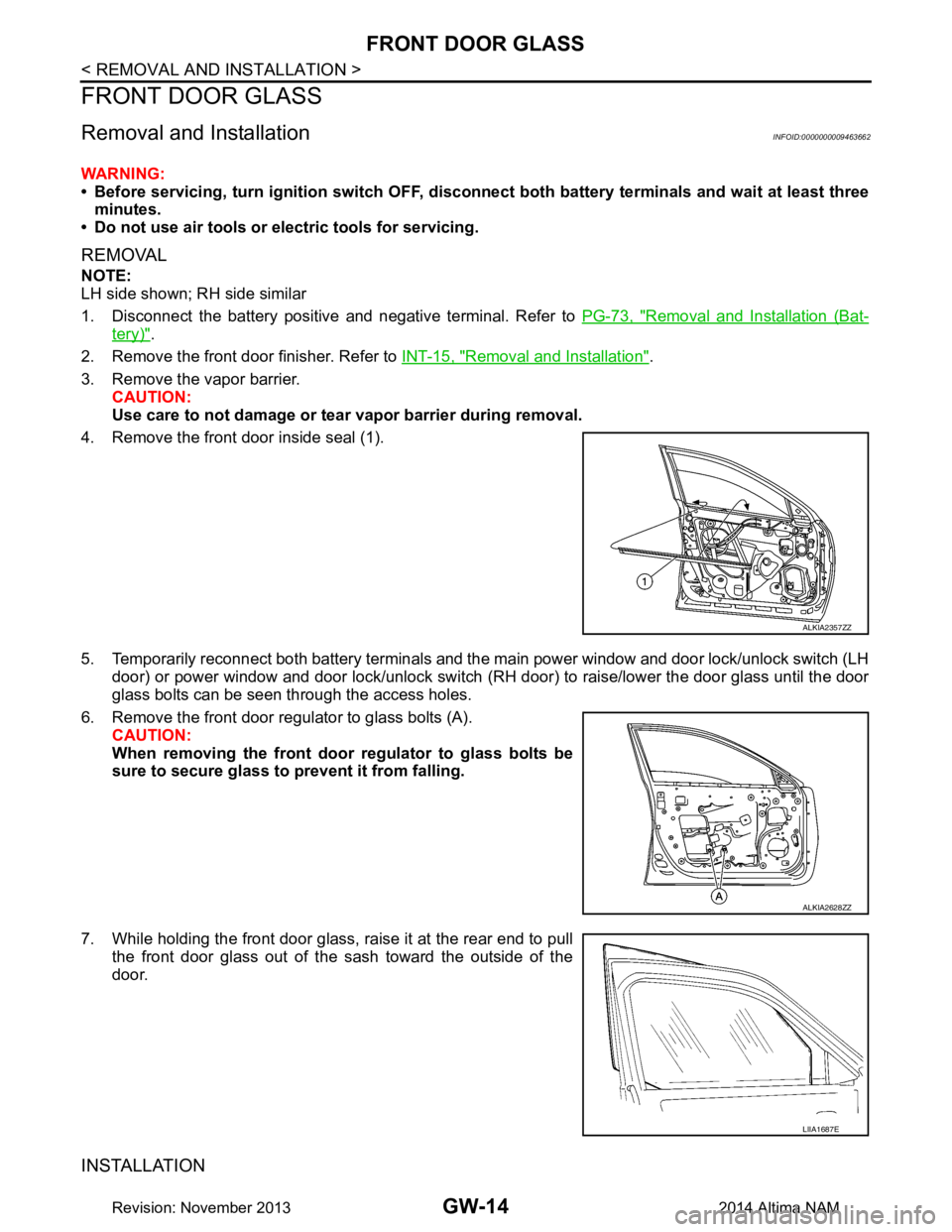
4. Remove the front door inside seal (1).
5. Temporarily reconnect both battery terminals and the main power window and door lock/unlock switch (LH door) or power window and door lock/unlock switch ( RH door) to raise/lower the door glass until the door
glass bolts can be seen through the access holes.
6. Remove the front door regul ator to glass bolts (A).
CAUTION:
When removing the front door regulator to glass bolts be
sure to secure glass to prevent it from falling.
7. While holding the front door glass, raise it at the rear end to pull the front door glass out of the sash toward the outside of the
door.
INSTALLATION
ALKIA2357ZZ
ALKIA2628ZZ
LIIA1687E
Revision: November 20132014 Altima NAM