ESP NISSAN TERRANO 2002 Service Repair Manual
[x] Cancel search | Manufacturer: NISSAN, Model Year: 2002, Model line: TERRANO, Model: NISSAN TERRANO 2002Pages: 1767, PDF Size: 41.51 MB
Page 2 of 1767
FOREWORD
This manual contains maintenance and repair procedures for NISSAN
TERRANO, model R20 series.
In order to assure your safety and the efficient functioning of the vehicle,
this manual should be read thoroughly. It is especially important that the
PRECAUTIONS in the GI section be completely understood before starting
any repair task.
All information in this manual is based on the latest product information
at the time of publication. The right is reserved to make changes in speci-
fications and methods at any time without notice.
IMPORTANT SAFETY NOTICE
The proper performance of service is essential for both the safety of the
technician and the efficient functioning of the vehicle.
The service methods in this Service Manual are described in such a man-
ner that the service may be performed safely and accurately.
Service varies with the procedures used, the skills of the technician and the
tools and parts available. Accordingly, anyone using service procedures,
tools or parts which are not specifically recommended by NISSAN must
first completely satisfy himself that neither his safety nor the vehicle's
safety will be jeopardized by the service method selected.
NISSAN EUROPE N.V.
Service Operations Section
Paris, France
Page 15 of 1767
TCM FUNCTION
The function of the TCM is to:
IReceive input signals sent from various switches and sensors.
IDetermine required line pressure, shifting point, lock-up operation, and engine brake operation.
ISend required output signals to the respective solenoids.
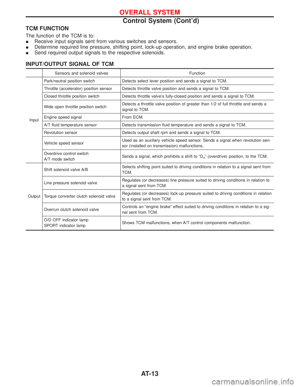
INPUT/OUTPUT SIGNAL OF TCM
Sensors and solenoid valves Function
InputPark/neutral position switch Detects select lever position and sends a signal to TCM.
Throttle (accelerator) position sensor Detects throttle valve position and sends a signal to TCM.
Closed throttle position switch Detects throttle valve's fully-closed position and sends a signal to TCM.
Wide open throttle position switchDetects a throttle valve position of greater than 1/2 of full throttle and sends a
signal to TCM.
Engine speed signal From ECM.
A/T fluid temperature sensor Detects transmission fluid temperature and sends a signal to TCM.
Revolution sensor Detects output shaft rpm and sends a signal to TCM.
Vehicle speed sensorUsed as an auxiliary vehicle speed sensor. Sends a signal when revolution sen-
sor (installed on transmission) malfunctions.
Overdrive control switch
A/T mode switchSends a signal, which prohibits a shift to ªD
4º (overdrive) position, to the TCM.
OutputShift solenoid valve A/BSelects shifting point suited to driving conditions in relation to a signal sent from
TCM.
Line pressure solenoid valveRegulates (or decreases) line pressure suited to driving conditions in relation to
a signal sent from TCM.
Torque converter clutch solenoid valveRegulates (or decreases) lock-up pressure suited to driving conditions in relation
to a signal sent from TCM.
Overrun clutch solenoid valveControls an ªengine brakeº effect suited to driving conditions in relation to a sig-
nal sent from TCM.
O/D OFF indicator lamp
SPORT indicator lampShows TCM malfunctions, when A/T control components malfunction.
OVERALL SYSTEM
Control System (Cont'd)
AT-13
Page 24 of 1767
Introduction
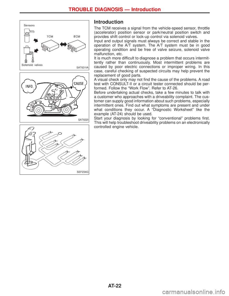
The TCM receives a signal from the vehicle-speed sensor, throttle
(accelerator) position sensor or park/neutral position switch and
provides shift control or lock-up control via solenoid valves.
Input and output signals must always be correct and stable in the
operation of the A/T system. The A/T system must be in good
operating condition and be free of valve seizure, solenoid valve
malfunction, etc.
It is much more difficult to diagnose a problem that occurs intermit-
tently rather than continuously. Most intermittent problems are
caused by poor electric connections or improper wiring. In this
case, careful checking of suspected circuits may help prevent the
replacement of good parts.
A visual check only may not find the cause of the problems. A road
test with CONSULT-II or a circuit tester connected should be per-
formed. Follow the ªWork Flowº. Refer to AT-26.
Before undertaking actual checks, take a few minutes to talk with
a customer who approaches with a driveability complaint. The cus-
tomer can supply good information about such problems, especially
intermittent ones. Find out what symptoms are present and under
what conditions they occur. A ªDiagnostic Worksheetº like the
example (AT-24) should be used.
Start your diagnosis by looking for ªconventionalº problems first.
This will help troubleshoot driveability problems on an electronically
controlled engine vehicle.
SAT631IA
SAT632I
SEF234G
TROUBLE DIAGNOSIS Ð Introduction
AT-22
Page 32 of 1767
Line Pressure Test
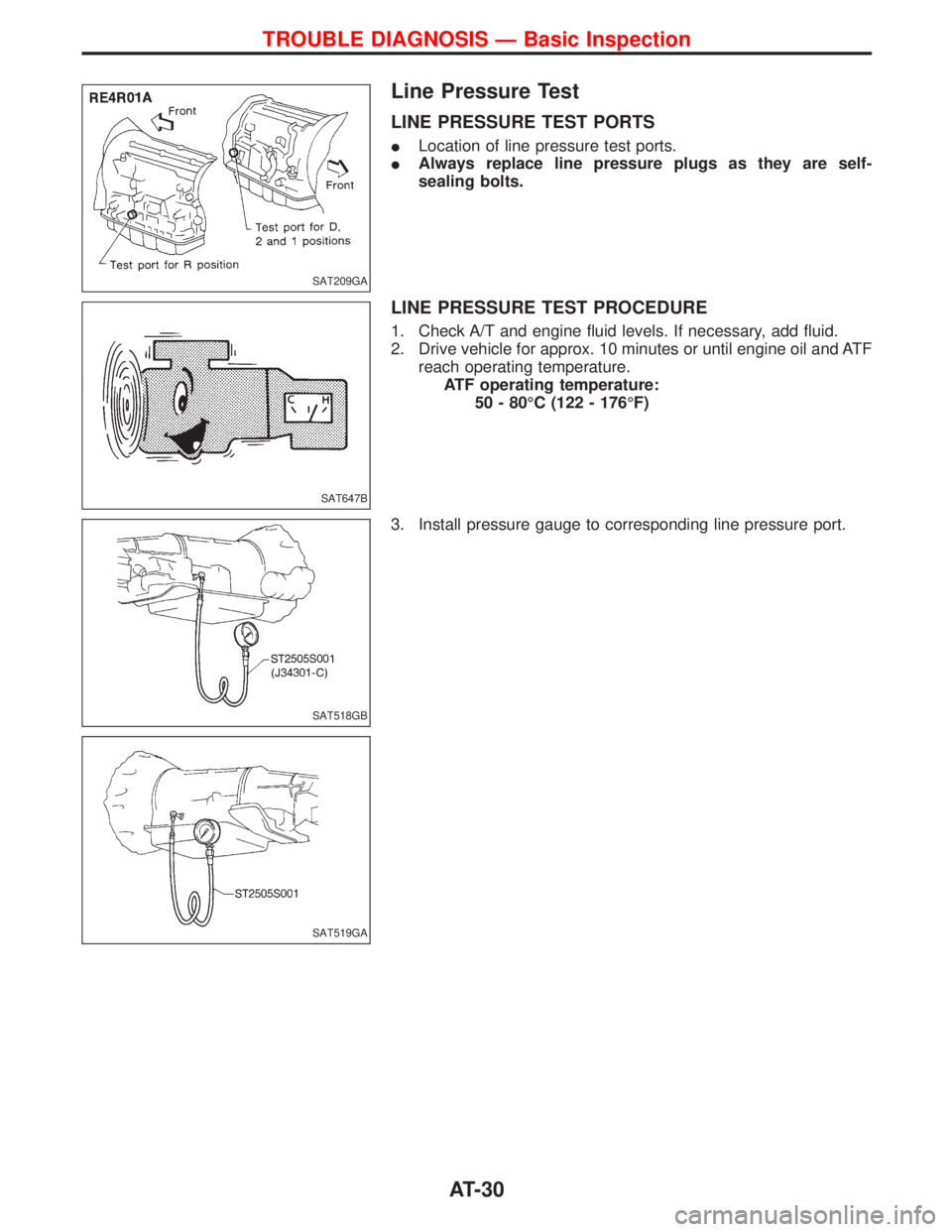
LINE PRESSURE TEST PORTS
ILocation of line pressure test ports.
IAlways replace line pressure plugs as they are self-
sealing bolts.
LINE PRESSURE TEST PROCEDURE
1. Check A/T and engine fluid levels. If necessary, add fluid.
2. Drive vehicle for approx. 10 minutes or until engine oil and ATF
reach operating temperature.
ATF operating temperature:
50 - 80ÉC (122 - 176ÉF)
3. Install pressure gauge to corresponding line pressure port.
SAT209GA
SAT647B
SAT518GB
SAT519GA
TROUBLE DIAGNOSIS Ð Basic Inspection
AT-30
Page 50 of 1767
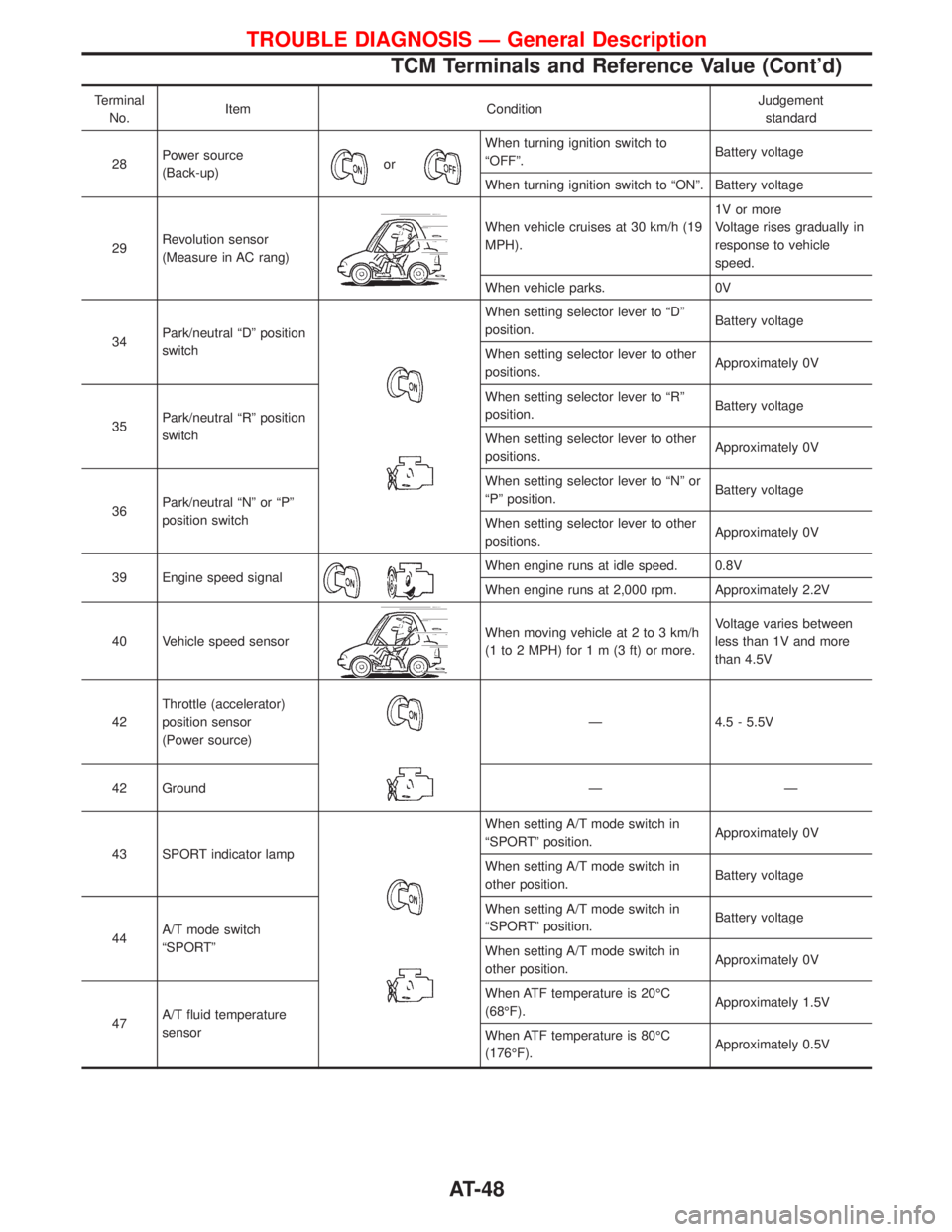
Terminal
No.Item ConditionJudgement
standard
28Power source
(Back-up)
or
When turning ignition switch to
ªOFFº.Battery voltage
When turning ignition switch to ªONº. Battery voltage
29Revolution sensor
(Measure in AC rang)
When vehicle cruises at 30 km/h (19
MPH).1V or more
Voltage rises gradually in
response to vehicle
speed.
When vehicle parks. 0V
34Park/neutral ªDº position
switch
When setting selector lever to ªDº
position.Battery voltage
When setting selector lever to other
positions.Approximately 0V
35Park/neutral ªRº position
switchWhen setting selector lever to ªRº
position.Battery voltage
When setting selector lever to other
positions.Approximately 0V
36Park/neutral ªNº or ªPº
position switchWhen setting selector lever to ªNº or
ªPº position.Battery voltage
When setting selector lever to other
positions.Approximately 0V
39 Engine speed signal
When engine runs at idle speed. 0.8V
When engine runs at 2,000 rpm. Approximately 2.2V
40 Vehicle speed sensor
When moving vehicle at 2 to 3 km/h
(1 to 2 MPH) for1m(3ft)ormore.Voltage varies between
less than 1V and more
than 4.5V
42Throttle (accelerator)
position sensor
(Power source)
Ð 4.5 - 5.5V
42 Ground Ð Ð
43 SPORT indicator lamp
When setting A/T mode switch in
ªSPORTº position.Approximately 0V
When setting A/T mode switch in
other position.Battery voltage
44A/T mode switch
ªSPORTºWhen setting A/T mode switch in
ªSPORTº position.Battery voltage
When setting A/T mode switch in
other position.Approximately 0V
47A/T fluid temperature
sensorWhen ATF temperature is 20ÉC
(68ÉF).Approximately 1.5V
When ATF temperature is 80ÉC
(176ÉF).Approximately 0.5V
TROUBLE DIAGNOSIS Ð General Description
TCM Terminals and Reference Value (Cont'd)
AT-48
Page 53 of 1767
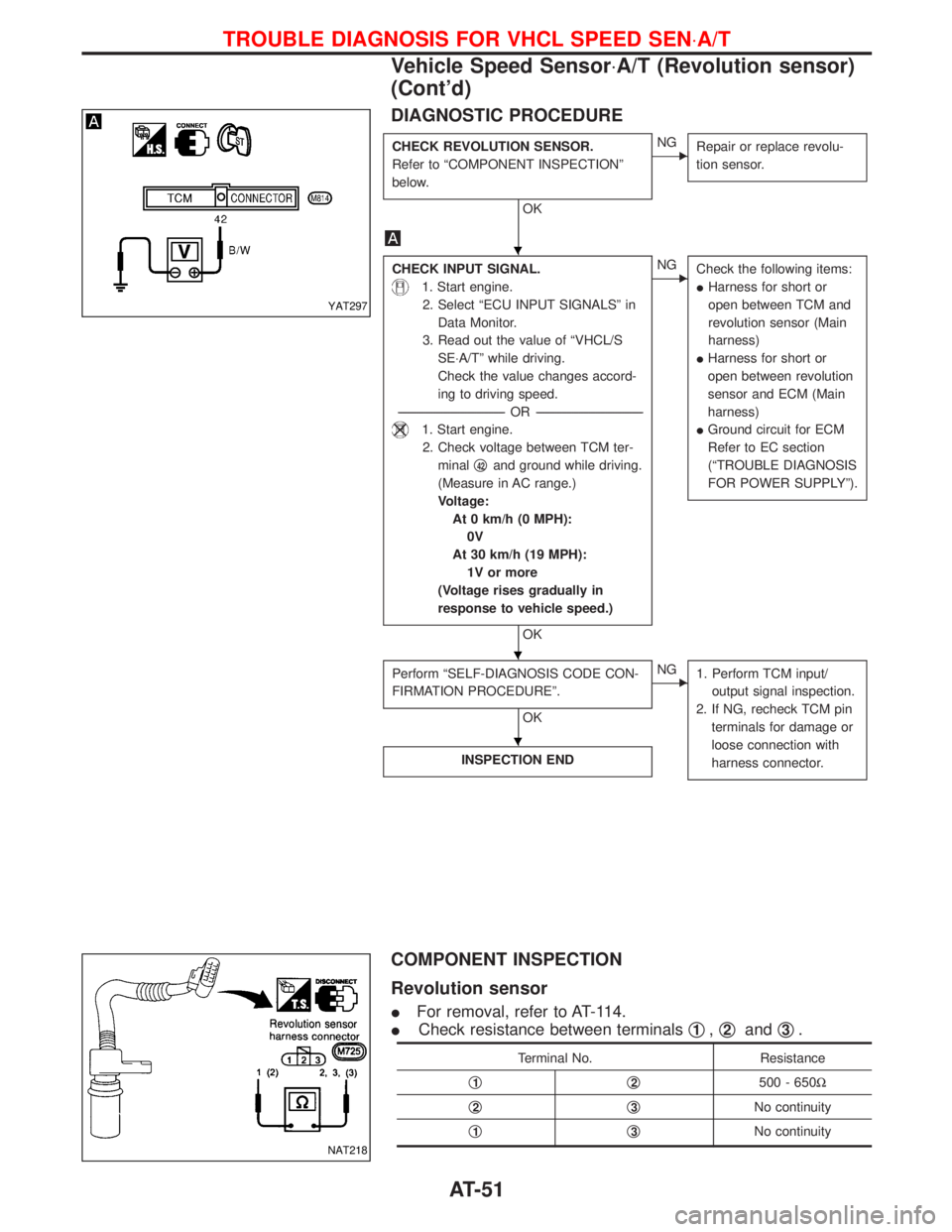
DIAGNOSTIC PROCEDURE
CHECK REVOLUTION SENSOR.
Refer to ªCOMPONENT INSPECTIONº
below.
OK
ENG
Repair or replace revolu-
tion sensor.
CHECK INPUT SIGNAL.
1. Start engine.
2. Select ªECU INPUT SIGNALSº in
Data Monitor.
3. Read out the value of ªVHCL/S
SE×A/Tº while driving.
Check the value changes accord-
ing to driving speed.
-----------------------------------------------------------------------------------------------------------------------OR -----------------------------------------------------------------------------------------------------------------------
1. Start engine.
2. Check voltage between TCM ter-
minalq
42and ground while driving.
(Measure in AC range.)
Voltage:
At 0 km/h (0 MPH):
0V
At 30 km/h (19 MPH):
1V or more
(Voltage rises gradually in
response to vehicle speed.)
OK
ENG
Check the following items:
IHarness for short or
open between TCM and
revolution sensor (Main
harness)
IHarness for short or
open between revolution
sensor and ECM (Main
harness)
IGround circuit for ECM
Refer to EC section
(ªTROUBLE DIAGNOSIS
FOR POWER SUPPLYº).
Perform ªSELF-DIAGNOSIS CODE CON-
FIRMATION PROCEDUREº.
OK
ENG
1. Perform TCM input/
output signal inspection.
2. If NG, recheck TCM pin
terminals for damage or
loose connection with
harness connector.
INSPECTION END
COMPONENT INSPECTION
Revolution sensor
IFor removal, refer to AT-114.
ICheck resistance between terminalsq
1,q2andq3.
Terminal No. Resistance
q
1q2500 - 650W
q
2q3No continuity
q
1q3No continuity
YAT297
NAT218
H
H
H
TROUBLE DIAGNOSIS FOR VHCL SPEED SEN×A/T
Vehicle Speed Sensor×A/T (Revolution sensor)
(Cont'd)
AT-51
Page 63 of 1767
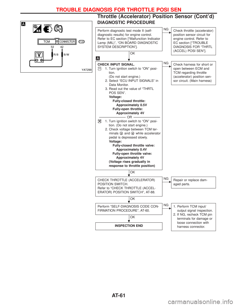
DIAGNOSTIC PROCEDURE
Perform diagnostic test mode II (self-
diagnostic results) for engine control.
Refer to EC section [ªMalfunction Indicator
Lamp (MIL)º, ªON BOARD DIAGNOSTIC
SYSTEM DESCRIPTIONº].
OK
ENG
Check throttle (accelerator)
position sensor circuit for
engine control. Refer to
EC section [ªTROUBLE
DIAGNOSIS FOR ªTHRTL
(ACCEL) POSI SENº].
CHECK INPUT SIGNAL.
1. Turn ignition switch to ªONº posi-
tion.
(Do not start engine.)
2. Select ªECU INPUT SIGNALSº in
Data Monitor.
3. Read out the value of ªTHRTL
POS SENº.
Voltage:
Fully-closed throttle:
Approximately 0.5V
Fully-open throttle:
Approximately 4V
-----------------------------------------------------------------------------------------------------------------------OR -----------------------------------------------------------------------------------------------------------------------
1. Turn ignition switch to ªONº posi-
tion. (Do not start engine.)
2. Check voltage between TCM ter-
minalsq
32andq42while accelerator
pedal is depressed slowly.
Voltage:
Fully-closed throttle valve:
Approximately 0.4V
Fully-open throttle valve:
Approximately 4V
(Voltage rises gradually in
response to throttle position)
OK
ENG
Check harness for short or
open between ECM and
TCM regarding throttle
(accelerator) position sen-
sor circuit. (Main harness)
CHECK THROTTLE (ACCELERATOR)
POSITION SWITCH.
Refer to ªCHECK THROTTLE (ACCEL-
ERATOR) POSITION SWITCHº, AT-88.
OK
ENG
Repair or replace dam-
aged parts.
Perform ªSELF-DIAGNOSIS CODE CON-
FIRMATION PROCEDUREº, AT-60.
OK
ENG
1. Perform TCM input/
output signal inspection.
2. If NG, recheck TCM pin
terminals for damage or
loose connection with
harness connector.
INSPECTION END
YAT299
H
H
H
H
TROUBLE DIAGNOSIS FOR THROTTLE POSI SEN
Throttle (Accelerator) Position Sensor (Cont'd)
AT-61
Page 65 of 1767
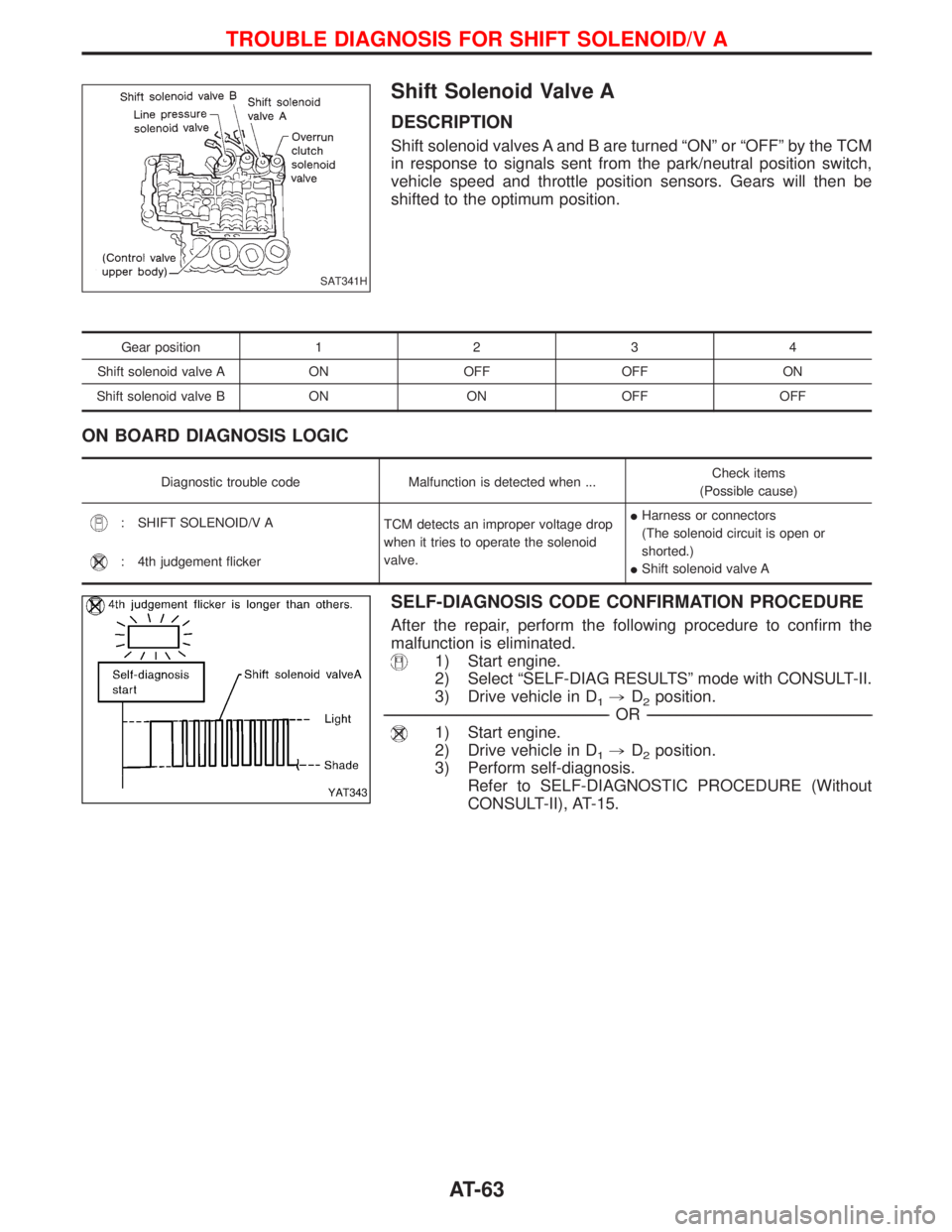
Shift Solenoid Valve A
DESCRIPTION
Shift solenoid valves A and B are turned ªONº or ªOFFº by the TCM
in response to signals sent from the park/neutral position switch,
vehicle speed and throttle position sensors. Gears will then be
shifted to the optimum position.
Gear position1234
Shift solenoid valve A ON OFF OFF ON
Shift solenoid valve B ON ON OFF OFF
ON BOARD DIAGNOSIS LOGIC
Diagnostic trouble code Malfunction is detected when ...Check items
(Possible cause)
: SHIFT SOLENOID/V A
TCM detects an improper voltage drop
when it tries to operate the solenoid
valve.IHarness or connectors
(The solenoid circuit is open or
shorted.)
IShift solenoid valve A
: 4th judgement flicker
SELF-DIAGNOSIS CODE CONFIRMATION PROCEDURE
After the repair, perform the following procedure to confirm the
malfunction is eliminated.
1) Start engine.
2) Select ªSELF-DIAG RESULTSº mode with CONSULT-II.
3) Drive vehicle in D
1,D2position.
------------------------------------------------------------------------------------------------------------------------------------------------------------------------------------------------------------------------------------------------------------OR------------------------------------------------------------------------------------------------------------------------------------------------------------------------------------------------------------------------------------------------------------
1) Start engine.
2) Drive vehicle in D
1,D2position.
3) Perform self-diagnosis.
Refer to SELF-DIAGNOSTIC PROCEDURE (Without
CONSULT-II), AT-15.
SAT341H
YAT343
TROUBLE DIAGNOSIS FOR SHIFT SOLENOID/V A
AT-63
Page 68 of 1767
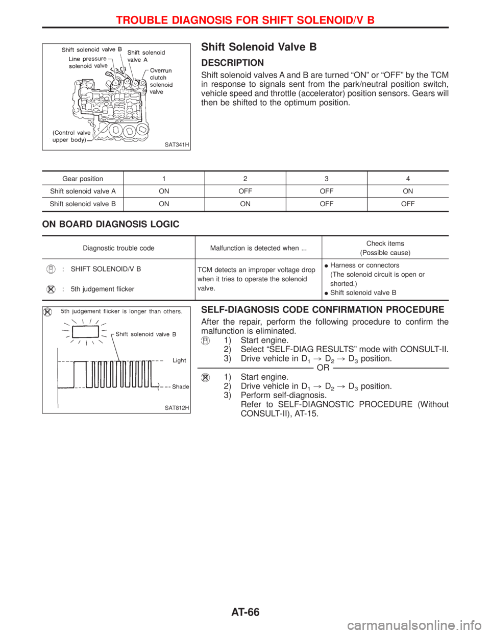
Shift Solenoid Valve B
DESCRIPTION
Shift solenoid valves A and B are turned ªONº or ªOFFº by the TCM
in response to signals sent from the park/neutral position switch,
vehicle speed and throttle (accelerator) position sensors. Gears will
then be shifted to the optimum position.
Gear position1234
Shift solenoid valve A ON OFF OFF ON
Shift solenoid valve B ON ON OFF OFF
ON BOARD DIAGNOSIS LOGIC
Diagnostic trouble code Malfunction is detected when ...Check items
(Possible cause)
: SHIFT SOLENOID/V B
TCM detects an improper voltage drop
when it tries to operate the solenoid
valve.IHarness or connectors
(The solenoid circuit is open or
shorted.)
IShift solenoid valve B
: 5th judgement flicker
SELF-DIAGNOSIS CODE CONFIRMATION PROCEDURE
After the repair, perform the following procedure to confirm the
malfunction is eliminated.
1) Start engine.
2) Select ªSELF-DIAG RESULTSº mode with CONSULT-II.
3) Drive vehicle in D
1,D2,D3position.
------------------------------------------------------------------------------------------------------------------------------------------------------------------------------------------------------------------------------------------------------------OR------------------------------------------------------------------------------------------------------------------------------------------------------------------------------------------------------------------------------------------------------------
1) Start engine.
2) Drive vehicle in D
1,D2,D3position.
3) Perform self-diagnosis.
Refer to SELF-DIAGNOSTIC PROCEDURE (Without
CONSULT-II), AT-15.
SAT341H
SAT812H
TROUBLE DIAGNOSIS FOR SHIFT SOLENOID/V B
AT-66
Page 71 of 1767
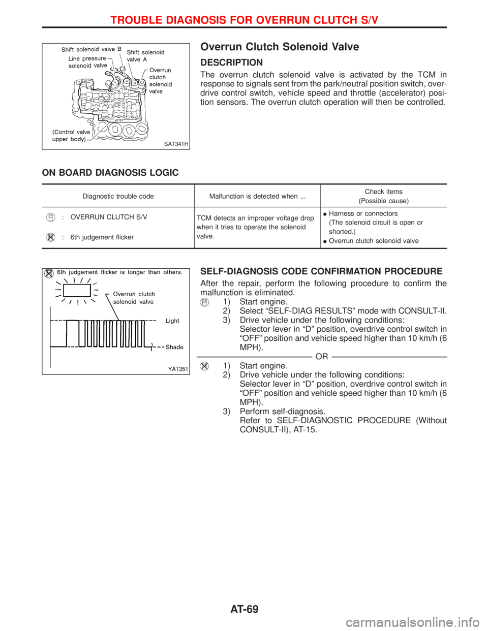
Overrun Clutch Solenoid Valve
DESCRIPTION
The overrun clutch solenoid valve is activated by the TCM in
response to signals sent from the park/neutral position switch, over-
drive control switch, vehicle speed and throttle (accelerator) posi-
tion sensors. The overrun clutch operation will then be controlled.
ON BOARD DIAGNOSIS LOGIC
Diagnostic trouble code Malfunction is detected when ...Check items
(Possible cause)
: OVERRUN CLUTCH S/V
TCM detects an improper voltage drop
when it tries to operate the solenoid
valve.IHarness or connectors
(The solenoid circuit is open or
shorted.)
IOverrun clutch solenoid valve
: 6th judgement flicker
SELF-DIAGNOSIS CODE CONFIRMATION PROCEDURE
After the repair, perform the following procedure to confirm the
malfunction is eliminated.
1) Start engine.
2) Select ªSELF-DIAG RESULTSº mode with CONSULT-II.
3) Drive vehicle under the following conditions:
Selector lever in ªDº position, overdrive control switch in
ªOFFº position and vehicle speed higher than 10 km/h (6
MPH).
------------------------------------------------------------------------------------------------------------------------------------------------------------------------------------------------------------------------------------------------------------OR------------------------------------------------------------------------------------------------------------------------------------------------------------------------------------------------------------------------------------------------------------
1) Start engine.
2) Drive vehicle under the following conditions:
Selector lever in ªDº position, overdrive control switch in
ªOFFº position and vehicle speed higher than 10 km/h (6
MPH).
3) Perform self-diagnosis.
Refer to SELF-DIAGNOSTIC PROCEDURE (Without
CONSULT-II), AT-15.
SAT341H
YAT351
TROUBLE DIAGNOSIS FOR OVERRUN CLUTCH S/V
AT-69