VEHICLE INFORMATION NISSAN TERRANO 2002 Service Repair Manual
[x] Cancel search | Manufacturer: NISSAN, Model Year: 2002, Model line: TERRANO, Model: NISSAN TERRANO 2002Pages: 1767, PDF Size: 41.51 MB
Page 2 of 1767
FOREWORD
This manual contains maintenance and repair procedures for NISSAN
TERRANO, model R20 series.
In order to assure your safety and the efficient functioning of the vehicle,
this manual should be read thoroughly. It is especially important that the
PRECAUTIONS in the GI section be completely understood before starting
any repair task.
All information in this manual is based on the latest product information
at the time of publication. The right is reserved to make changes in speci-
fications and methods at any time without notice.
IMPORTANT SAFETY NOTICE
The proper performance of service is essential for both the safety of the
technician and the efficient functioning of the vehicle.
The service methods in this Service Manual are described in such a man-
ner that the service may be performed safely and accurately.
Service varies with the procedures used, the skills of the technician and the
tools and parts available. Accordingly, anyone using service procedures,
tools or parts which are not specifically recommended by NISSAN must
first completely satisfy himself that neither his safety nor the vehicle's
safety will be jeopardized by the service method selected.
NISSAN EUROPE N.V.
Service Operations Section
Paris, France
Page 22 of 1767
Diagnosis by CONSULT-II
NOTICE
1. The CONSULT-II electrically displays shift timing and lock-up timing (that is, operation timing of each
solenoid).
Check for time difference between actual shift timing and the CONSULT-II display. If the difference is
noticeable, mechanical parts (except solenoids, sensors, etc.) may be malfunctioning. Check mechanical
parts using applicable diagnostic procedures.
2. Shift schedule (which implies gear position) displayed on CONSULT-II and that indicated in Service Manual
may differ slightly. This occurs because of the following reasons:
IActual shift schedule has more or less tolerance or allowance,
IShift schedule indicated in Service Manual refers to the point where shifts start. Gear position displayed
on CONSULT-II indicates the point where shifts are completed.
3. Shift solenoid valve ªAº or ªBº is displayed on CONSULT-II at the start of shifting. Gear position is displayed
upon completion of shifting (which is computed by TCM).
4. Additional CONSULT-II information can be found in the Operation Manual supplied with the CONSULT-II
unit.
SELF-DIAGNOSTIC RESULT TEST MODE
Refer to AT-14.
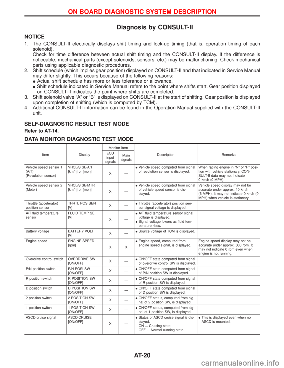
DATA MONITOR DIAGNOSTIC TEST MODE
Item DisplayMonitor item
Description Remarks ECU
input
signalsMain
signals
Vehicle speed sensor 1
(A/T)
(Revolution sensor)VHCL/S SE×A/T
[km/h] or [mph]
XÐIVehicle speed computed from signal
of revolution sensor is displayed.When racing engine in ªNº or ªPº posi-
tion with vehicle stationary, CON-
SULT-II data may not indicate
0 km/h (0 MPH).
Vehicle speed sensor 2
(Meter)VHCL/S SE×MTR
[km/h] or [mph]
XÐIVehicle speed computed from signal
of vehicle speed sensor is dis-
played.Vehicle speed display may not be
accurate under approx. 10 km/h
(6 MPH). It may not indicate 0 km/h (0
MPH) when vehicle is stationary.
Throttle (accelerator)
position sensorTHRTL POS SEN
[V]XÐIThrottle (accelerator) position sen-
sor signal voltage is displayed.
A/T fluid temperature
sensorFLUID TEMP SE
[V]
XÐIA/T fluid temperature sensor signal
voltage is displayed.
ISignal voltage lowers as fluid tem-
perature rises.
Battery voltage BATTERY VOLT
[V]XÐISource voltage of TCM is displayed.
Engine speed ENGINE SPEED
[rpm]
XXIEngine speed, computed from
engine speed signal, is displayed.Engine speed display may not be
accurate under approx. 800 rpm. It
may not indicate 0 rpm even when
engine is not running.
Overdrive control switch OVERDRIVE SW
[ON/OFF]XÐION/OFF state computed from signal
of overdrive control SW is displayed.
P/N position switch P/N POSI SW
[ON/OFF]XÐION/OFF state computed from signal
of P/N position SW is displayed.
R position switch R POSITION SW
[ON/OFF]XÐION/OFF state computed from signal
of R position SW is displayed.
D position switch D POSITION SW
[ON/OFF]XÐION/OFF state computed from signal
of D position SW is displayed.
2 position switch 2 POSITION SW
[ON/OFF]XÐION/OFF status, computed from sig-
nal of 2 position SW, is displayed.
1 position switch 1 POSITION SW
[ON/OFF]XÐION/OFF status, computed from sig-
nal of 1 position SW, is displayed.
ASCD-cruise signal ASCD×CRUISE
[ON/OFF]
XÐIStatus of ASCD cruise signal is dis-
played.
ON ... Cruising state
OFF ... Normal running stateIThis is displayed even when no
ASCD is mounted.
ON BOARD DIAGNOSTIC SYSTEM DESCRIPTION
AT-20
Page 24 of 1767
Introduction
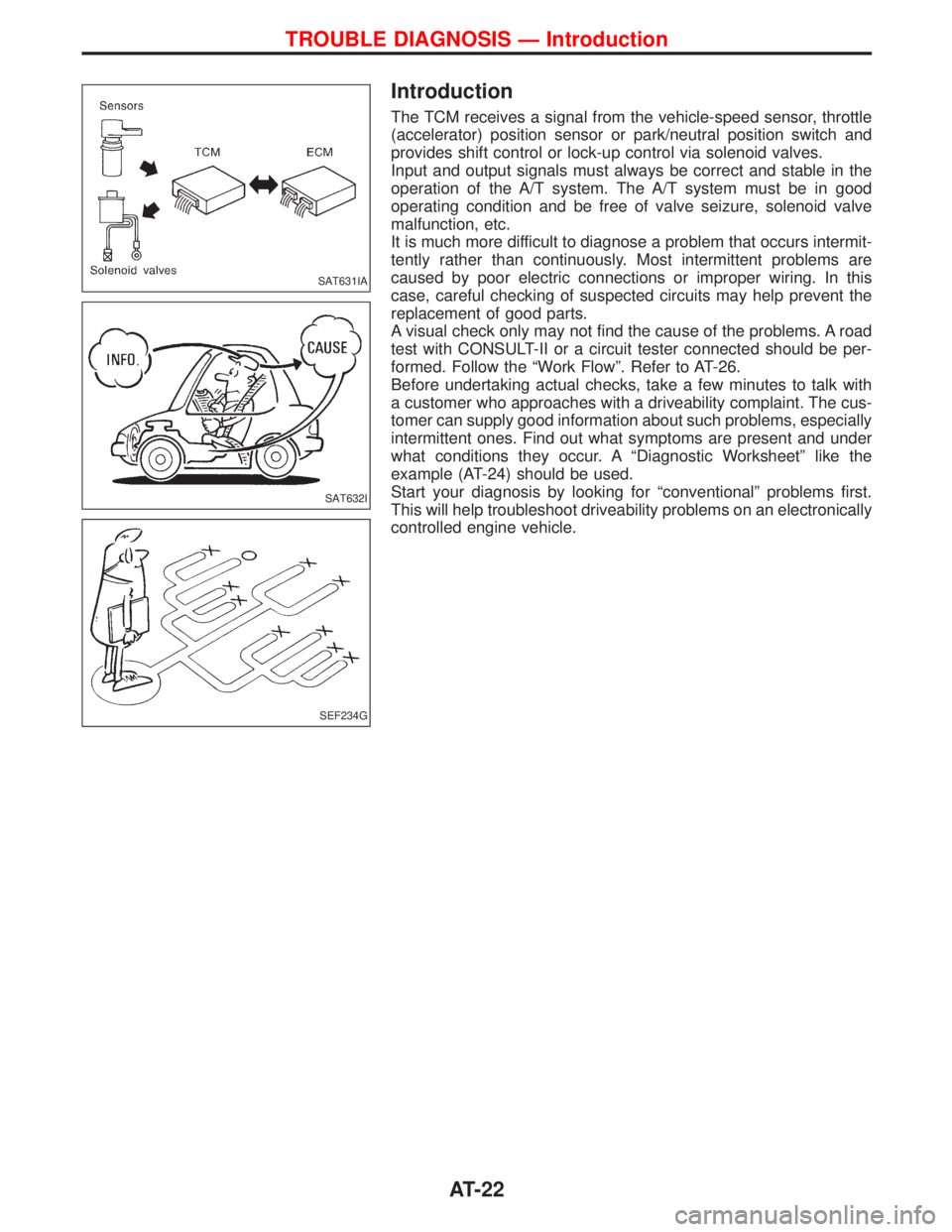
The TCM receives a signal from the vehicle-speed sensor, throttle
(accelerator) position sensor or park/neutral position switch and
provides shift control or lock-up control via solenoid valves.
Input and output signals must always be correct and stable in the
operation of the A/T system. The A/T system must be in good
operating condition and be free of valve seizure, solenoid valve
malfunction, etc.
It is much more difficult to diagnose a problem that occurs intermit-
tently rather than continuously. Most intermittent problems are
caused by poor electric connections or improper wiring. In this
case, careful checking of suspected circuits may help prevent the
replacement of good parts.
A visual check only may not find the cause of the problems. A road
test with CONSULT-II or a circuit tester connected should be per-
formed. Follow the ªWork Flowº. Refer to AT-26.
Before undertaking actual checks, take a few minutes to talk with
a customer who approaches with a driveability complaint. The cus-
tomer can supply good information about such problems, especially
intermittent ones. Find out what symptoms are present and under
what conditions they occur. A ªDiagnostic Worksheetº like the
example (AT-24) should be used.
Start your diagnosis by looking for ªconventionalº problems first.
This will help troubleshoot driveability problems on an electronically
controlled engine vehicle.
SAT631IA
SAT632I
SEF234G
TROUBLE DIAGNOSIS Ð Introduction
AT-22
Page 25 of 1767
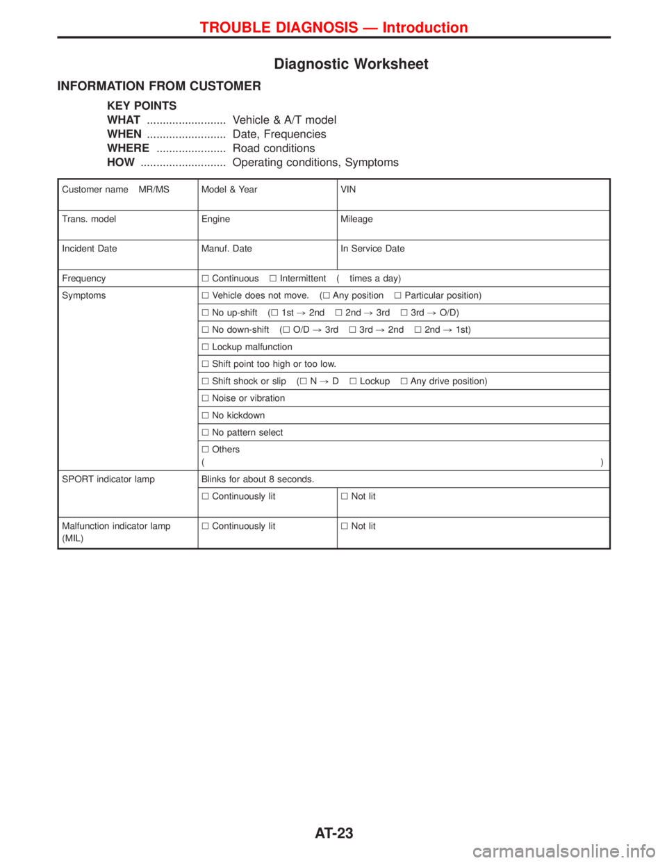
Diagnostic Worksheet
INFORMATION FROM CUSTOMER
KEY POINTS
WHAT......................... Vehicle & A/T model
WHEN......................... Date, Frequencies
WHERE...................... Road conditions
HOW........................... Operating conditions, Symptoms
Customer name MR/MS Model & Year VIN
Trans. model Engine Mileage
Incident Date Manuf. Date In Service Date
FrequencylContinuouslIntermittent ( times a day)
SymptomslVehicle does not move. (lAny positionlParticular position)
lNo up-shift (l1st,2ndl2nd,3rdl3rd,O/D)
lNo down-shift (lO/D,3rdl3rd,2ndl2nd,1st)
lLockup malfunction
lShift point too high or too low.
lShift shock or slip (lN,DlLockuplAny drive position)
lNoise or vibration
lNo kickdown
lNo pattern select
lOthers
()
SPORT indicator lamp Blinks for about 8 seconds.
lContinuously litlNot lit
Malfunction indicator lamp
(MIL)lContinuously litlNot lit
TROUBLE DIAGNOSIS Ð Introduction
AT-23
Page 249 of 1767
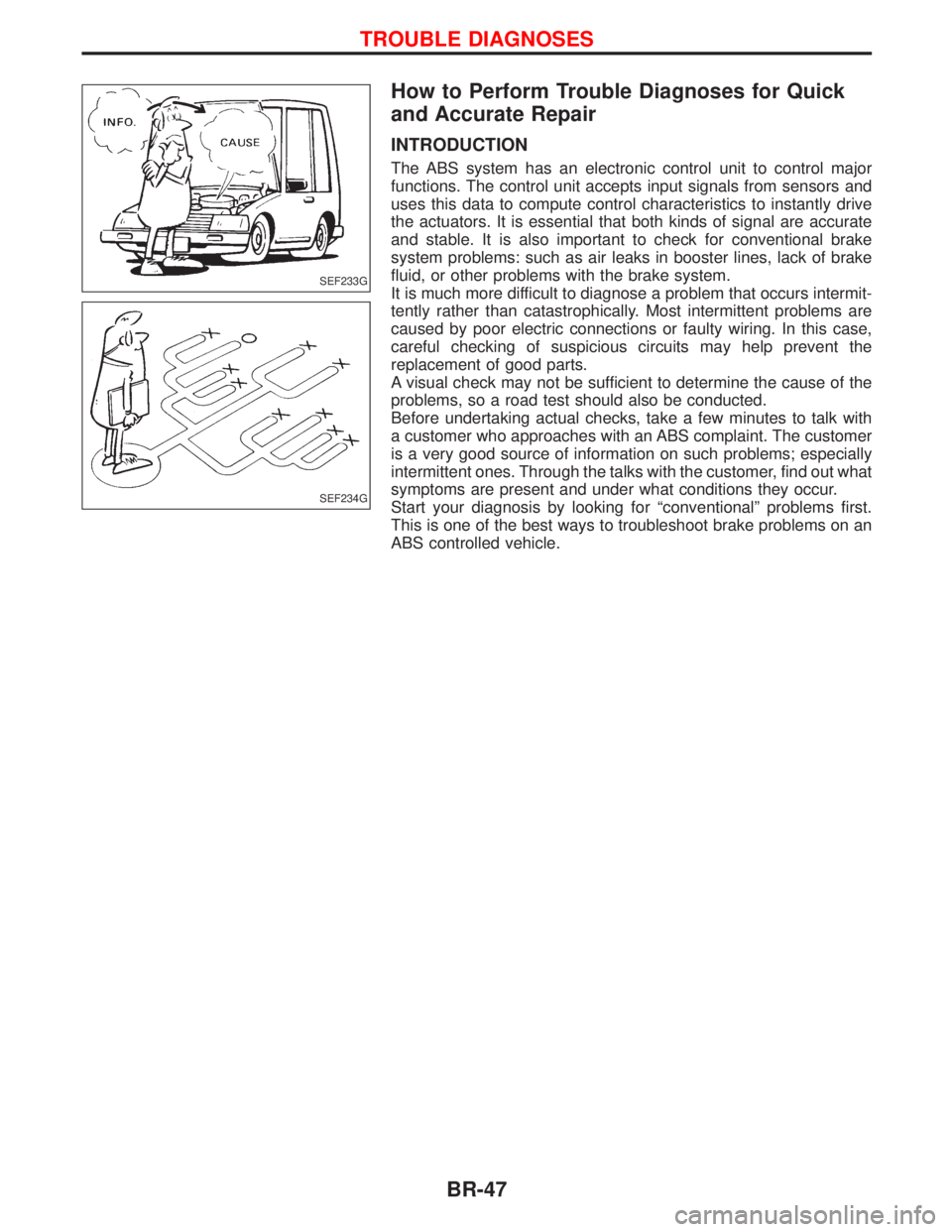
How to Perform Trouble Diagnoses for Quick
and Accurate Repair
INTRODUCTION
The ABS system has an electronic control unit to control major
functions. The control unit accepts input signals from sensors and
uses this data to compute control characteristics to instantly drive
the actuators. It is essential that both kinds of signal are accurate
and stable. It is also important to check for conventional brake
system problems: such as air leaks in booster lines, lack of brake
fluid, or other problems with the brake system.
It is much more difficult to diagnose a problem that occurs intermit-
tently rather than catastrophically. Most intermittent problems are
caused by poor electric connections or faulty wiring. In this case,
careful checking of suspicious circuits may help prevent the
replacement of good parts.
A visual check may not be sufficient to determine the cause of the
problems, so a road test should also be conducted.
Before undertaking actual checks, take a few minutes to talk with
a customer who approaches with an ABS complaint. The customer
is a very good source of information on such problems; especially
intermittent ones. Through the talks with the customer, find out what
symptoms are present and under what conditions they occur.
Start your diagnosis by looking for ªconventionalº problems first.
This is one of the best ways to troubleshoot brake problems on an
ABS controlled vehicle.
SEF233G
SEF234G
TROUBLE DIAGNOSES
BR-47
Page 290 of 1767
Service Notice
IWhen removing or installing various parts, place a cloth or padding onto the vehicle body to prevent
scratches.
IHandle trim, molding, instruments, grille, etc. carefully during removing or installing. Be careful not to oil
or damage them.
IApply sealing compound where necessary when installing parts.
IWhen applying sealing compound, be careful that the sealing compound does not protrude from parts.
IWhen replacing any metal parts (for example body outer panel, members, etc.), be sure to take rust pre-
vention measures.
Supplemental Restraint System (SRS) ªAIR
BAGº and ªSEAT BELT PRE-TENSIONERº
The Supplemental Restraint System such as ªAIR BAGº and ªSEAT BELT PRE-TENSIONERº used along with
a seat belt, helps to reduce the risk or severity of injury to the driver and front passenger for certain types of
collision. The SRS system composition which is available to NISSAN MODEL R20 is as follows (The compo-
sition varies according to the destination and optional equipment.):
IFor a frontal collision
The Supplemental Restraint System consists of driver air bag module (located in the center of the steer-
ing wheel), front passenger air bag module (located on the instrument panel on passenger side), front seat
belt pre-tensioners, a diagnosis sensor unit, warning lamp, wiring harness and spiral cable.
IFor a side collision
The Supplemental Restraint System consists of front side air bag module (located in the outer side of front
seat), side air bag (satellite) sensor, diagnosis sensor unit (one of components of air bags for a frontal
collision), wiring harness, warning lamp (one of components of air bags for a frontal collision).
Information necessary to service the system safely is included in theRSsection of this Service Manual.
WARNING:
ITo avoid rendering the SRS inoperative, which could increase the risk of personal injury or death
in the event of a collision which would result in air bag inflation, all maintenance should be per-
formed by an authorized NISSAN dealer.
IImproper maintenance, including incorrect removal and installation of the SRS, can lead to per-
sonal injury caused by unintentional activation of the system. For removal of Spiral Cable and Air
Bag Module, see the RS section.
IDo not use electrical test equipment on any circuit related to the SRS unless instructed to in this
Service Manual. Spiral cable and wiring harnesses covered with yellow insulation tape either just
before the harness connectors or for the complete harness are related to the SRS.
PRECAUTIONS
BT-2
Page 396 of 1767
IIf the battery is disconnected, the emission-related diagnostic information will be lost after approx.
24 hours.
IErasing the emission-related diagnostic information using CONSULT-II is easier and quicker than
switching the diagnostic test mode using the data link connector.
NATS (Nissan Anti-Theft System)
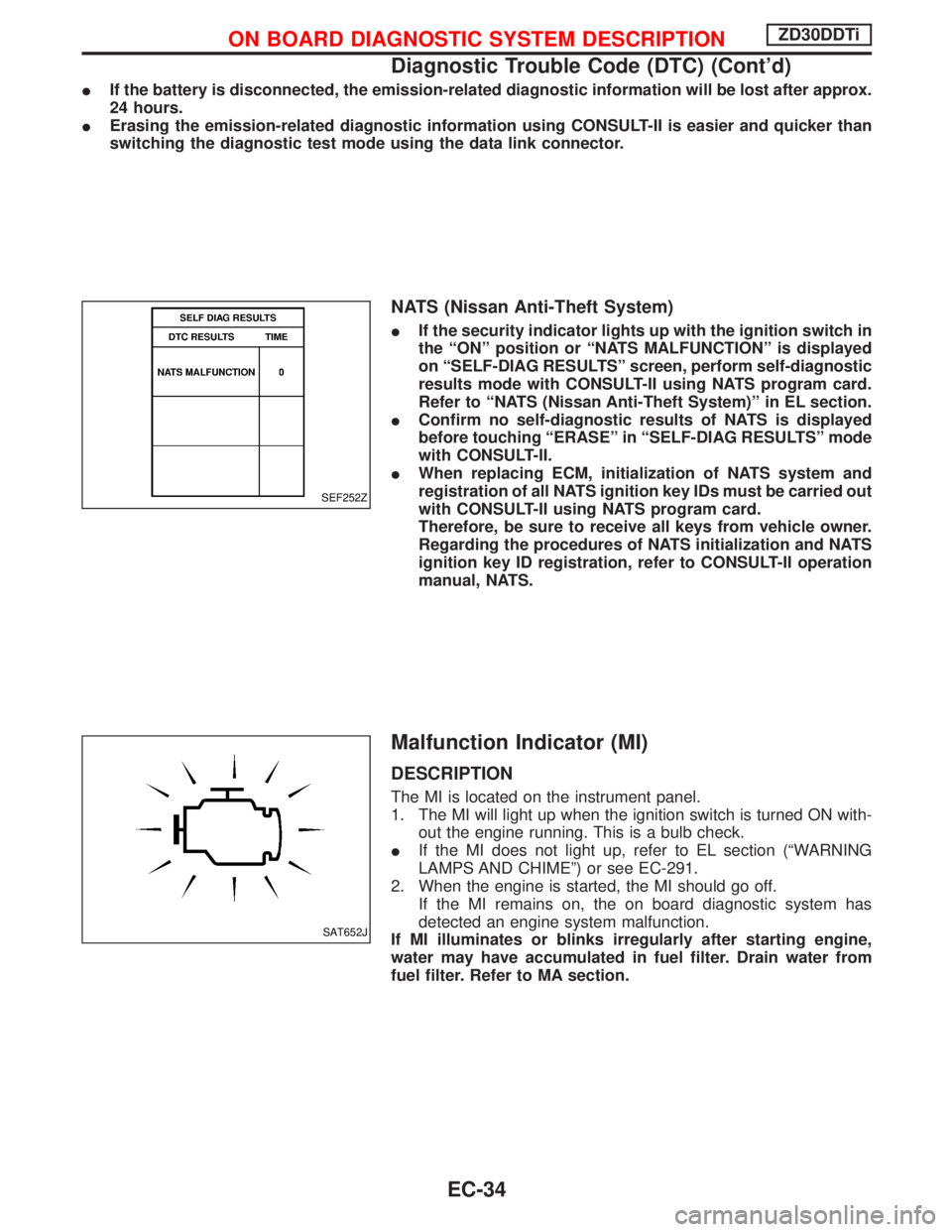
IIf the security indicator lights up with the ignition switch in
the ªONº position or ªNATS MALFUNCTIONº is displayed
on ªSELF-DIAG RESULTSº screen, perform self-diagnostic
results mode with CONSULT-II using NATS program card.
Refer to ªNATS (Nissan Anti-Theft System)º in EL section.
IConfirm no self-diagnostic results of NATS is displayed
before touching ªERASEº in ªSELF-DIAG RESULTSº mode
with CONSULT-II.
IWhen replacing ECM, initialization of NATS system and
registration of all NATS ignition key IDs must be carried out
with CONSULT-II using NATS program card.
Therefore, be sure to receive all keys from vehicle owner.
Regarding the procedures of NATS initialization and NATS
ignition key ID registration, refer to CONSULT-II operation
manual, NATS.
Malfunction Indicator (MI)
DESCRIPTION
The MI is located on the instrument panel.
1. The MI will light up when the ignition switch is turned ON with-
out the engine running. This is a bulb check.
IIf the MI does not light up, refer to EL section (ªWARNING
LAMPS AND CHIMEº) or see EC-291.
2. When the engine is started, the MI should go off.
If the MI remains on, the on board diagnostic system has
detected an engine system malfunction.
If MI illuminates or blinks irregularly after starting engine,
water may have accumulated in fuel filter. Drain water from
fuel filter. Refer to MA section.
SEF252Z
SAT652J
ON BOARD DIAGNOSTIC SYSTEM DESCRIPTIONZD30DDTi
Diagnostic Trouble Code (DTC) (Cont'd)
EC-34
Page 408 of 1767

Introduction
The engine has an ECM to control major systems such as fuel
injection control, fuel injection timing control, glow control system,
etc. The ECM accepts input signals from sensors and instantly
drives electronic control fuel injection pump. It is essential that both
input and output signals are proper and stable. At the same time,
it is important that there are no problems such as vacuum leaks,
or other problems with the engine.
It is much more difficult to diagnose a problem that occurs intermit-
tently rather than continuously. Most intermittent problems are
caused by poor electric connections or improper wiring. In this
case, careful checking of suspected circuits may help prevent the
replacement of good parts.
A visual check only may not find the cause of the problems. A road
test with CONSULT-II or a circuit tester connected should be per-
formed. Follow the ªWork Flowº, EC-48.
Before undertaking actual checks, take a few minutes to talk with
a customer who approaches with a driveability complaint. The cus-
tomer can supply good information about such problems, especially
intermittent ones. Find out what symptoms are present and under
what conditions they occur. A ªDiagnostic Worksheetº like the
example on next page should be used.
Start your diagnosis by looking for ªconventionalº problems first.
This will help troubleshoot driveability problems on an electronically
controlled engine vehicle.
DIAGNOSTIC WORKSHEET
There are many operating conditions that lead to the malfunction
of engine components. A good grasp of such conditions can make
troubleshooting faster and more accurate.
In general, each customer feels differently about a problem. It is
important to fully understand the symptoms or conditions for a
customer complaint.
Utilize a diagnostic worksheet like the one shown below in order to
organize all the information for troubleshooting.
SEF858S
SEF233G
SEF234G
SEF907L
TROUBLE DIAGNOSIS Ð INTRODUCTIONZD30DDTi
EC-46
Page 411 of 1767
DESCRIPTION FOR WORK FLOW
STEP DESCRIPTION
STEP IGet detailed information about the conditions and the environment when the incident/symptom occurred using
the ªDIAGNOSTIC WORKSHEETº, EC-46.
STEP IIBefore confirming the concern, check and write down (print out using CONSULT-II) the DTC, then erase the
DTC. Refer to EC-33.
If the incident cannot be verified, perform ªTROUBLE DIAGNOSIS FOR INTERMITTENT INCIDENTº, EC-78.
Study the relationship between the cause, specified by DTC, and the symptom described by the customer. (The
ªSymptom Matrix Chartº will be useful. Refer to EC-56.) Also check related service bulletins for information.
STEP IIITry to confirm the symptom and under what conditions the incident occurs.
The ªDIAGNOSTIC WORK SHEETº is useful to verify the incident. Connect CONSULT-II to the vehicle in DATA
MONITOR (AUTO TRIG) mode and check real time diagnosis results.
If the incident cannot be verified, perform ªTROUBLE DIAGNOSIS FOR INTERMITTENT INCIDENTº, EC-78.
If the malfunction code is detected, skip STEP IV and perform STEP V.
STEP IVTry to detect the DTC by driving in (or performing) the ªDTC Confirmation Procedureº. Check and read the DTC
by using CONSULT-II.
During the DTC verification, be sure to connect CONSULT-II to the vehicle in DATA MONITOR (AUTO TRIG)
mode and check real time diagnosis results.
If the incident cannot be verified, perform ªTROUBLE DIAGNOSIS FOR INTERMITTENT INCIDENTº, EC-78.
In case the ªDTC Confirmation Procedureº is not available, perform the ªOverall Function Checkº instead. The
DTC cannot be displayed by this check, however, this simplified ªcheckº is an effective alternative.
The ªNGº result of the ªOverall Function Checkº is the same as the DTC detection.
STEP VTake the appropriate action based on the results of STEP I through IV.
If the malfunction code is indicated, proceed to TROUBLE DIAGNOSIS FOR DTC XXXX.
If the normal code is indicated, proceed to the Basic Inspection, EC-50. Then perform inspections according to
the Symptom Matrix Chart. Refer to EC-56.
STEP VIIdentify where to begin diagnosis based on the relationship study between symptom and possible causes.
Inspect the system for mechanical binding, loose connectors or wiring damage using (tracing) ªHarness Layoutsº.
Gently shake the related connectors, components or wiring harness with CONSULT-II set in ªDATA MONITOR
(AUTO TRIG)º mode.
Check the voltage of the related ECM terminals or monitor the output data from the related sensors with CON-
SULT-II. Refer to EC-69 or EC-66.
The ªDiagnostic Procedureº in EC section contains a description based on open circuit inspection. A short circuit
inspection is also required for the circuit check in the Diagnostic Procedure. For details, refer to GI section (ªCir-
cuit Inspectionº, ªHOW TO PERFORM EFFICIENT DIAGNOSIS FOR AN ELECTRICAL INCIDENTº).
Repair or replace the malfunction parts.
If the malfunctioning part cannot be detected, perform ªTROUBLE DIAGNOSIS FOR INTERMITTENT
INCIDENTº, EC-78.
STEP VIIOnce you have repaired the circuit or replaced a component, you need to run the engine in the same conditions
and circumstances which resulted in the customer's initial complaint.
Perform the ªDTC Confirmation Procedureº and confirm the normal code (DTC No. 0505) is detected. If the inci-
dent is still detected in the final check, perform STEP VI by using a different method from the previous one.
Before returning the vehicle to the customer, be sure to erase the unnecessary (already fixed) DTC in ECM.
(Refer to EC-33.)
TROUBLE DIAGNOSIS Ð INTRODUCTIONZD30DDTi
Work Flow (Cont'd)
EC-49
Page 696 of 1767
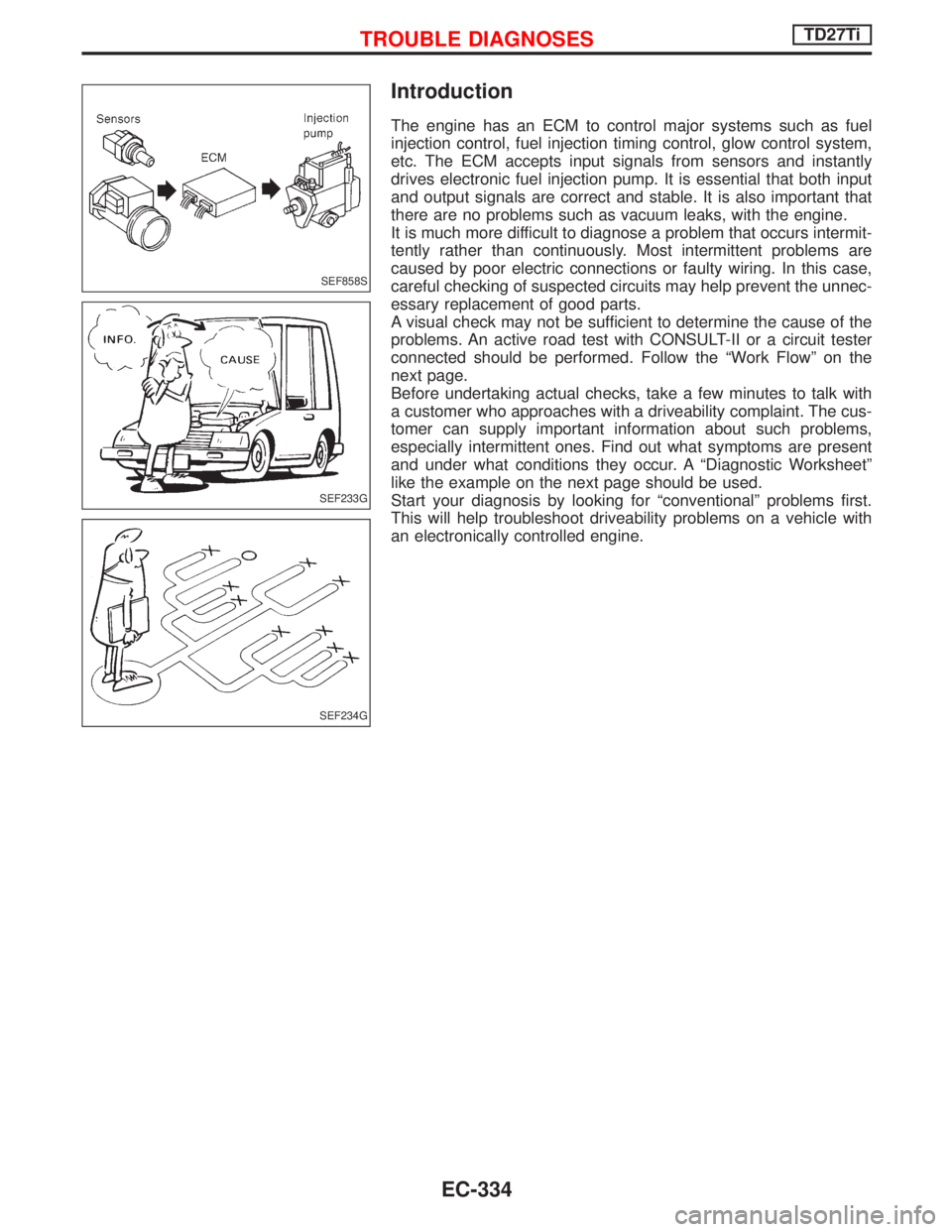
Introduction
The engine has an ECM to control major systems such as fuel
injection control, fuel injection timing control, glow control system,
etc. The ECM accepts input signals from sensors and instantly
drives electronic fuel injection pump. It is essential that both input
and output signals are correct and stable. It is also important that
there are no problems such as vacuum leaks, with the engine.
It is much more difficult to diagnose a problem that occurs intermit-
tently rather than continuously. Most intermittent problems are
caused by poor electric connections or faulty wiring. In this case,
careful checking of suspected circuits may help prevent the unnec-
essary replacement of good parts.
A visual check may not be sufficient to determine the cause of the
problems. An active road test with CONSULT-II or a circuit tester
connected should be performed. Follow the ªWork Flowº on the
next page.
Before undertaking actual checks, take a few minutes to talk with
a customer who approaches with a driveability complaint. The cus-
tomer can supply important information about such problems,
especially intermittent ones. Find out what symptoms are present
and under what conditions they occur. A ªDiagnostic Worksheetº
like the example on the next page should be used.
Start your diagnosis by looking for ªconventionalº problems first.
This will help troubleshoot driveability problems on a vehicle with
an electronically controlled engine.
SEF858S
SEF233G
SEF234G
TROUBLE DIAGNOSESTD27Ti
EC-334