oil dipstick NISSAN TERRANO 2002 Service Repair Manual
[x] Cancel search | Manufacturer: NISSAN, Model Year: 2002, Model line: TERRANO, Model: NISSAN TERRANO 2002Pages: 1767, PDF Size: 41.51 MB
Page 896 of 1767
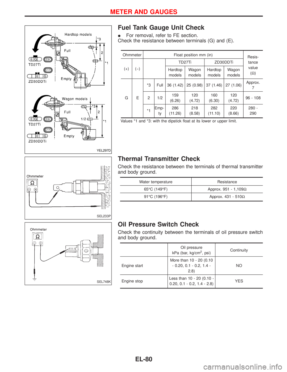
Fuel Tank Gauge Unit Check
IFor removal, refer to FE section.
Check the resistance between terminals (G) and (E).
Ohmmeter Float position mm (in)
Resis-
tance
value
(W) (+) (þ)TD27Ti ZD30DDTi
Hardtop
modelsWagon
modelsHardtop
modelsWagon
models
GE*3 Full 36 (1.42) 25 (0.98) 37 (1.46) 27 (1.06)Approx.
7
2 1/2159
(6.26)120
(4.72)160
(6.30)120
(4.72)96 - 108
*1Emp-
ty286
(11.26)218
(8.58)282
(11.10)220
(8.66)280 -
290
Values *1 and *3: with the dipstick float at its lower or upper limit.
Thermal Transmitter Check
Check the resistance between the terminals of thermal transmitter
and body ground.
Water temperature Resistance
65ÉC (149ÉF) Approx. 951 - 1,109W
91ÉC (196ÉF) Approx. 431 - 510W
Oil Pressure Switch Check
Check the continuity between the terminals of oil pressure switch
and body ground.
Oil pressure
kPa (bar, kg/cm2, psi)Continuity
Engine startMore than 10 - 20 (0.10
- 0.20, 0.1 - 0.2, 1.4 -
2.8)NO
Engine stopLess than 10 - 20 (0.10 -
0.20, 0.1 - 0.2, 1.4 - 2.8)YES
YEL297D
SEL233P
SEL748K
METER AND GAUGES
EL-80
Page 1125 of 1767
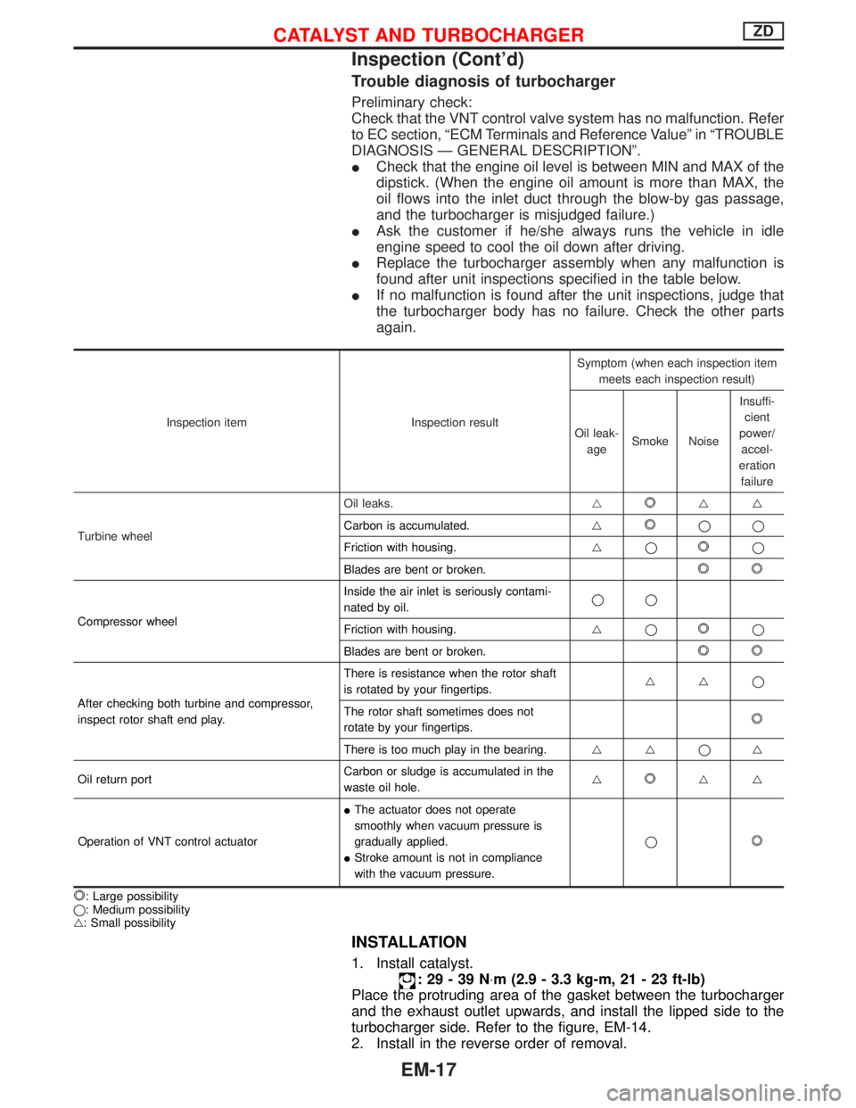
Trouble diagnosis of turbocharger
Preliminary check:
Check that the VNT control valve system has no malfunction. Refer
to EC section, ªECM Terminals and Reference Valueº in ªTROUBLE
DIAGNOSIS Ð GENERAL DESCRIPTIONº.
ICheck that the engine oil level is between MIN and MAX of the
dipstick. (When the engine oil amount is more than MAX, the
oil flows into the inlet duct through the blow-by gas passage,
and the turbocharger is misjudged failure.)
IAsk the customer if he/she always runs the vehicle in idle
engine speed to cool the oil down after driving.
IReplace the turbocharger assembly when any malfunction is
found after unit inspections specified in the table below.
IIf no malfunction is found after the unit inspections, judge that
the turbocharger body has no failure. Check the other parts
again.
Inspection item Inspection resultSymptom (when each inspection item
meets each inspection result)
Oil leak-
ageSmoke NoiseInsuffi-
cient
power/
accel-
eration
failure
Turbine wheelOil leaks.g
gg
Carbon is accumulated.g
qq
Friction with housing.gq
q
Blades are bent or broken.
Compressor wheelInside the air inlet is seriously contami-
nated by oil.qq
Friction with housing.gqq
Blades are bent or broken.
After checking both turbine and compressor,
inspect rotor shaft end play.There is resistance when the rotor shaft
is rotated by your fingertips.ggq
The rotor shaft sometimes does not
rotate by your fingertips.
There is too much play in the bearing.ggqg
Oil return portCarbon or sludge is accumulated in the
waste oil hole.g
gg
Operation of VNT control actuatorIThe actuator does not operate
smoothly when vacuum pressure is
gradually applied.
IStroke amount is not in compliance
with the vacuum pressure.q
: Large possibility
q: Medium possibility
g: Small possibility
INSTALLATION
1. Install catalyst.
:29-39N×m (2.9 - 3.3 kg-m, 21 - 23 ft-lb)
Place the protruding area of the gasket between the turbocharger
and the exhaust outlet upwards, and install the lipped side to the
turbocharger side. Refer to the figure, EM-14.
2. Install in the reverse order of removal.
CATALYST AND TURBOCHARGERZD
Inspection (Cont'd)
EM-17
Page 1210 of 1767
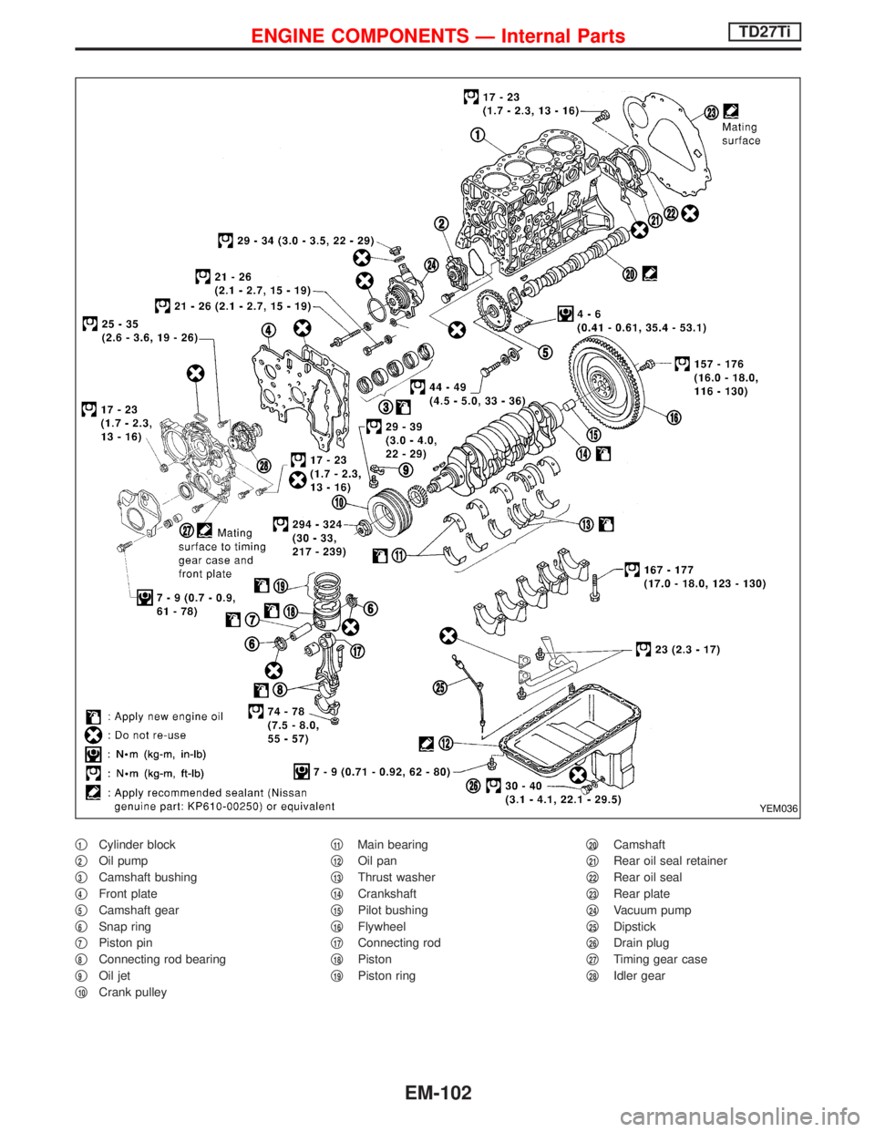
q1Cylinder block
q
2Oil pump
q
3Camshaft bushing
q
4Front plate
q
5Camshaft gear
q
6Snap ring
q
7Piston pin
q
8Connecting rod bearing
q
9Oil jet
q
10Crank pulleyq
11Main bearing
q
12Oil pan
q
13Thrust washer
q
14Crankshaft
q
15Pilot bushing
q
16Flywheel
q
17Connecting rod
q
18Piston
q
19Piston ringq
20Camshaft
q
21Rear oil seal retainer
q
22Rear oil seal
q
23Rear plate
q
24Vacuum pump
q
25Dipstick
q
26Drain plug
q
27Timing gear case
q
28Idler gear
YEM036
ENGINE COMPONENTS Ð Internal PartsTD27Ti
EM-102
Page 1480 of 1767
Changing Engine Oil
WARNING:
IBe careful not to burn yourself, as the engine oil is hot.
IProlonged and repeated contact with used engine oil may
cause skin cancer; try to avoid direct skin contact with
used oil. If skin contact is made, wash thoroughly with
soap or hand cleaner as soon as possible.
1. Warm up engine, and check for oil leakage from engine com-
ponents.
2. Stop engine.
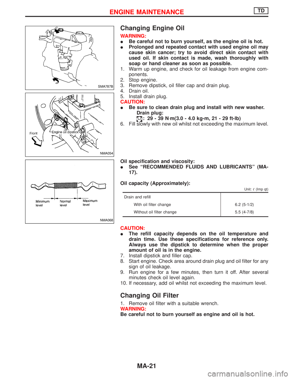
3. Remove dipstick, oil filler cap and drain plug.
4. Drain oil.
5. Install drain plug.
CAUTION:
IBe sure to clean drain plug and install with new washer.
Drain plug:
: 29-39N×m(3.0 - 4.0 kg-m, 21 - 29 ft-lb)
6. Fill slowly with new oil whilst not exceeding the maximum level.
Oil specification and viscosity:
ISee ªRECOMMENDED FLUIDS AND LUBRICANTSº (MA-
17).
Oil capacity (Approximately):
Unit:(Imp qt)
Drain and refill
With oil filter change 6.2 (5-1/2)
Without oil filter change 5.5 (4-7/8)
CAUTION:
IThe refill capacity depends on the oil temperature and
drain time. Use these specifications for reference only.
Always use the dipstick to determine when the proper
amount of oil is in the engine.
7. Install dipstick and filler cap.
8. Start engine. Check area around drain plug and oil filter for any
sign of oil leakage.
9. Run engine for a few minutes, then turn it off. After several
minutes check oil level again.
10. If necessary, add oil whilst not exceeding the maximum level.
Changing Oil Filter
1. Remove oil filter with a suitable wrench.
WARNING:
Be careful not to burn yourself as engine and oil is hot.
SMA787B
NMA054
NMA068
ENGINE MAINTENANCETD
MA-21
Page 1489 of 1767
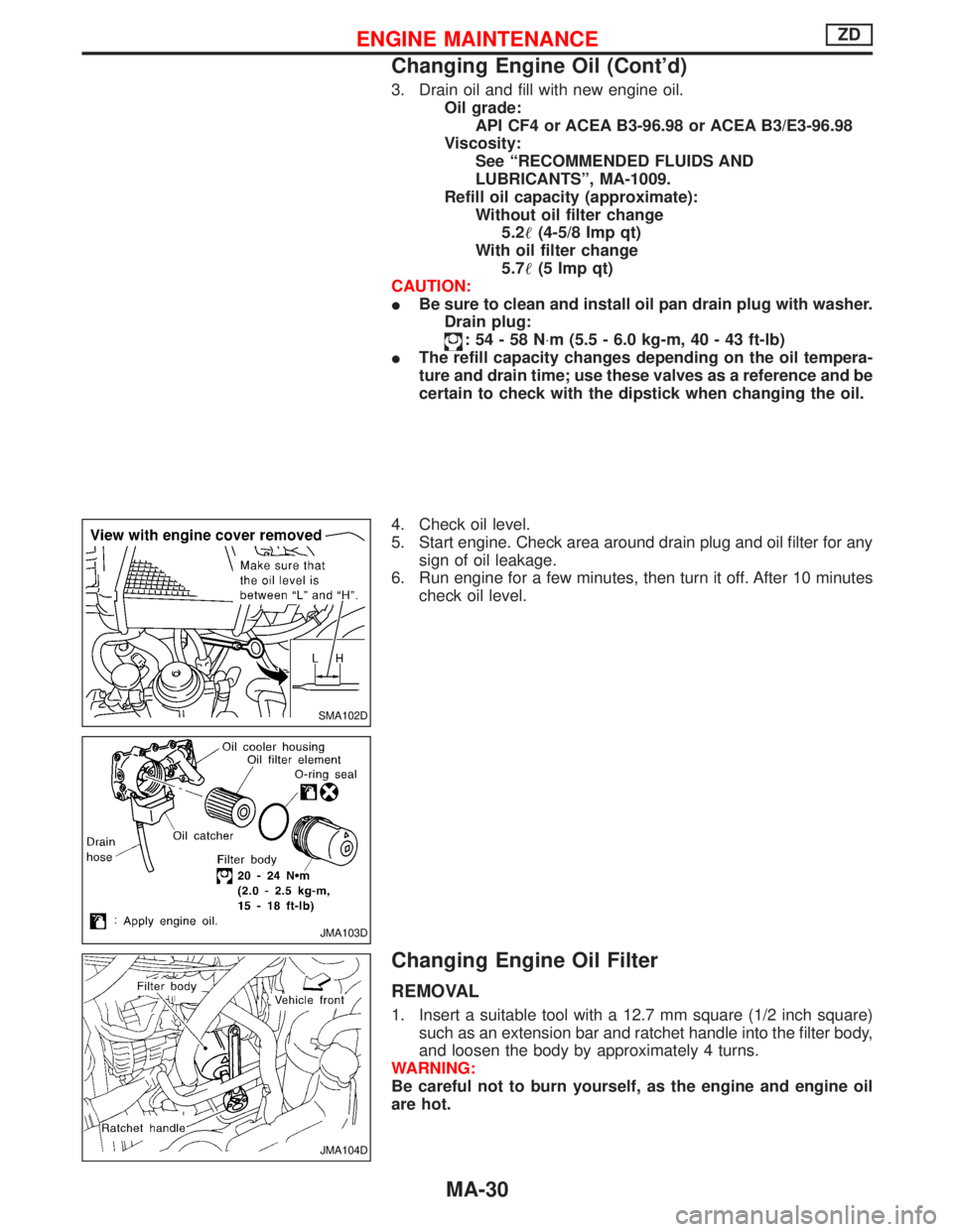
3. Drain oil and fill with new engine oil.
Oil grade:
API CF4 or ACEA B3-96.98 or ACEA B3/E3-96.98
Viscosity:
See ªRECOMMENDED FLUIDS AND
LUBRICANTSº, MA-1009.
Refill oil capacity (approximate):
Without oil filter change
5.2(4-5/8 Imp qt)
With oil filter change
5.7(5 Imp qt)
CAUTION:
IBe sure to clean and install oil pan drain plug with washer.
Drain plug:
:54-58N×m (5.5 - 6.0 kg-m, 40 - 43 ft-lb)
IThe refill capacity changes depending on the oil tempera-
ture and drain time; use these valves as a reference and be
certain to check with the dipstick when changing the oil.
4. Check oil level.
5. Start engine. Check area around drain plug and oil filter for any
sign of oil leakage.
6. Run engine for a few minutes, then turn it off. After 10 minutes
check oil level.
Changing Engine Oil Filter
REMOVAL
1. Insert a suitable tool with a 12.7 mm square (1/2 inch square)
such as an extension bar and ratchet handle into the filter body,
and loosen the body by approximately 4 turns.
WARNING:
Be careful not to burn yourself, as the engine and engine oil
are hot.
SMA102D
JMA103D
JMA104D
ENGINE MAINTENANCEZD
Changing Engine Oil (Cont'd)
MA-30