charging NISSAN TERRANO 2002 Service Repair Manual
[x] Cancel search | Manufacturer: NISSAN, Model Year: 2002, Model line: TERRANO, Model: NISSAN TERRANO 2002Pages: 1767, PDF Size: 41.51 MB
Page 1 of 1767
Edition: February 2002
Release: February 2002 (01)
Publication No.: SM2E00-1R20E0E
GENERAL INFORMATIONGI
MAINTENANCEMA
ENGINE MECHANICALEM
ENGINE LUBRICATION &
COOLING SYSTEMSLC
ENGINE CONTROL SYSTEMEC
ACCELERATOR CONTROL,
FUEL & EXHAUST SYSTEMFE
CLUTCHCL
MANUAL TRANSMISSIONMT
AUTOMATIC TRANSMISSIONAT
TRANSFERTF
PROPELLER SHAFT &
DIFFERENTIAL CARRIERPD
FRONT AXLE & FRONT SUSPENSIONFA
REAR AXLE & REAR SUSPENSIONRA
BRAKE SYSTEMBR
STEERING SYSTEMST
RESTRAINT SYSTEMRS
BODY & TRIMBT
HEATER & AIR CONDITIONERHA
STARTING & CHARGING SYSTEMSSC
ELECTRICAL SYSTEMEL
ALPHABETICAL INDEXIDX
TERRANO
MODEL R20 SERIES
NISSAN EUROPE N.V.
NISSAN EUROPE N.V.
Produced in The Netherlands
QUICK REFERENCE INDEX
Page 47 of 1767
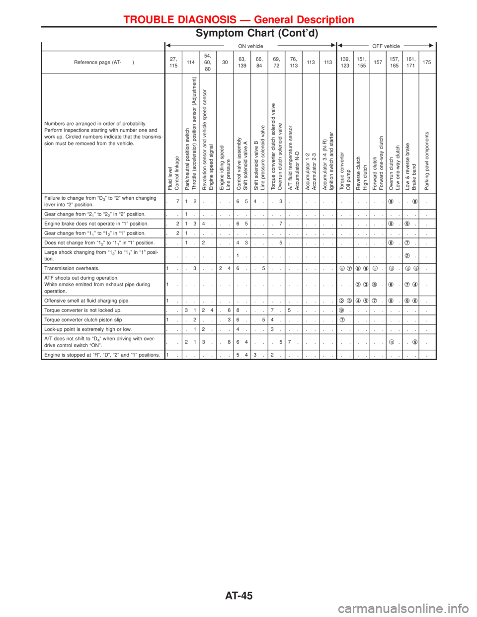
FON vehicleEFOFF vehicleE
Reference page (AT- )27,
11 511 454,
60,
803063,
13966,
8469,
7276,
11 311 3 11 3139,
123151,
155157157,
165161,
171175
Numbers are arranged in order of probability.
Perform inspections starting with number one and
work up. Circled numbers indicate that the transmis-
sion must be removed from the vehicle.
Fluid level
Control linkage
Park/neutral position switch
Throttle (accelerator) position sensor (Adjustment)
Revolution sensor and vehicle speed sensor
Engine speed signal
Engine idling speed
Line pressure
Control valve assembly
Shift solenoid valve A
Shift solenoid valve B
Line pressure solenoid valve
Torque converter clutch solenoid valve
Overrun clutch solenoid valve
A/T fluid temperature sensor
Accumulator N-D
Accumulator 1-2
Accumulator 2-3
Accumulator 3-4 (N-R)
Ignition switch and starter
Torque converter
Oil pump
Reverse clutch
High clutch
Forward clutch
Forward one-way clutch
Overrun clutch
Low one-way clutch
Low & reverse brake
Brake band
Parking pawl components
Failure to change from ªD3º to ª2º when changing
lever into ª2º position.. 712....654..3...... ......q9..q8.
Gear change from ª2
1ºtoª22º in ª2º position. . . 1................. .......... .
Engine brake does not operate in ª1º position. .2134 . . . 65 . . . 7...... ......q
8.q9..
Gear change from ª1
1ºtoª12º in ª1º position. . 2 1................. .......... .
Does not change from ª1
2ºtoª11º in ª1º position. . . 1 . 2 . . . 4 3 . . . 5...... ......q6.q7..
Large shock changing from ª1
2ºtoª11º in ª1º posi-
tion.. .......1........... ........q2..
Transmission overheats. 1 . . 3 . . 2 4 6 . . 5........q
14q7q8q9q11.q12.q13q10.
ATF shoots out during operation.
White smoke emitted from exhaust pipe during
operation.1 ................... ..q
2q3q5.q6.q7q4.
Offensive smell at fluid charging pipe. 1...................q
2q3q4q5q7.q8.q9q6.
Torque converter is not locked up. . .3124 . 68 . . . 7 . 5.....q
9......... .
Torque converter clutch piston slip 1 . . 2 . . . 3 6 . . 5 4.......q
7......... .
Lock-up point is extremely high or low. . . . 1 2 . . . 4 . . . 3....... .......... .
A/T does not shift to ªD
4º when driving with over-
drive control switch ªONº.. .213..864...57..... ......q10..q9.
Engine is stopped at ªRº, ªDº, ª2º and ª1º positions. 1.......543.2....... .......... .
TROUBLE DIAGNOSIS Ð General Description
Symptom Chart (Cont'd)
AT-45
Page 118 of 1767
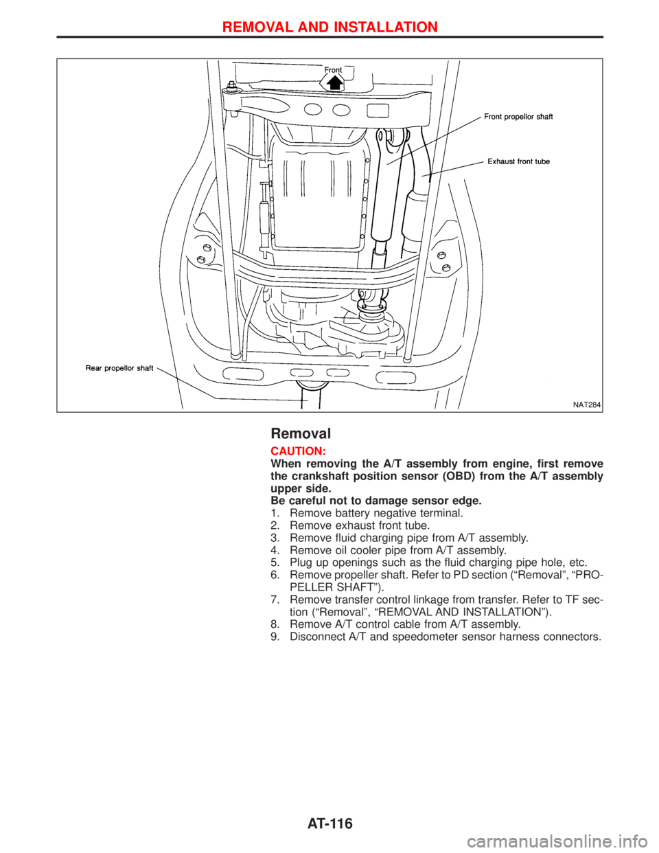
Removal
CAUTION:
When removing the A/T assembly from engine, first remove
the crankshaft position sensor (OBD) from the A/T assembly
upper side.
Be careful not to damage sensor edge.
1. Remove battery negative terminal.
2. Remove exhaust front tube.
3. Remove fluid charging pipe from A/T assembly.
4. Remove oil cooler pipe from A/T assembly.
5. Plug up openings such as the fluid charging pipe hole, etc.
6. Remove propeller shaft. Refer to PD section (ªRemovalº, ªPRO-
PELLER SHAFTº).
7. Remove transfer control linkage from transfer. Refer to TF sec-
tion (ªRemovalº, ªREMOVAL AND INSTALLATIONº).
8. Remove A/T control cable from A/T assembly.
9. Disconnect A/T and speedometer sensor harness connectors.
NAT284
REMOVAL AND INSTALLATION
AT-116
Page 515 of 1767
On Board Diagnosis Logic
The ECM checks if battery voltage is within the tolerance range for the engine control system.
Malfunction is detected when ... Check Items (Possible Cause)
IAn abnormally high voltage from the battery is sent to ECM.IIncorrect jump starting
IBattery
IAlternator
IECM
DTC Confirmation Procedure
With CONSULT-II
1) Check the following.
IJumper cables are connected for jump starting.
IBattery or alternator has been replaced.
If the result is ªYesº for one item or more, skip the following steps and go to ªDiagnostic Procedureº,
EC-153.
2) Check that the positive battery terminal is connected to battery properly. If NG, reconnect it properly.
3) Check that the alternator functions properly. Refer to EL section (ªCHARGING SYSTEMº).
4) Turn ignition switch ªONº and select ªDATA MONITORº mode with CONSULT-II.
5) Wait one minute.
6) If DTC is detected, go to ªDiagnostic Procedureº, EC-153.
If DTC is not detected, go to next step.
7) Start engine and wait one minute at idle.
8) If DTC is detected, go to ªDiagnostic Procedureº, EC-153.
Without CONSULT-II
1) Check the following.
IJumper cables are connected for jump starting.
IBattery or alternator has been replaced.
If the result is ªYesº for one item or more, skip the following steps and go to ªDiagnostic Procedureº,
EC-153.
2) Check that the positive battery terminal is connected to battery properly. If NG, reconnect it properly.
3) Check that the alternator functions properly. Refer to EL section (ªCHARGING SYSTEMº).
4) Turn ignition switch ªONº and wait one minute.
5) Turn ignition switch ªOFFº, wait 5 seconds and then turn ªONº.
6) Perform ªDiagnostic Test Mode II (Self-diagnostic result)º with ECM.
7) If DTC is detected, go to ªDiagnostic Procedureº, EC-153.
If DTC is not detected, go to next step.
8) Start engine and wait one minute at idle.
9) Turn ignition switch ªOFFº, wait 5 seconds and then turn ªONº.
10) Perform ªDiagnostic Test Mode II (Self-diagnostic result)º with ECM.
11) If DTC is detected, go to ªDiagnostic Procedureº, EC-153.
Diagnostic Procedure
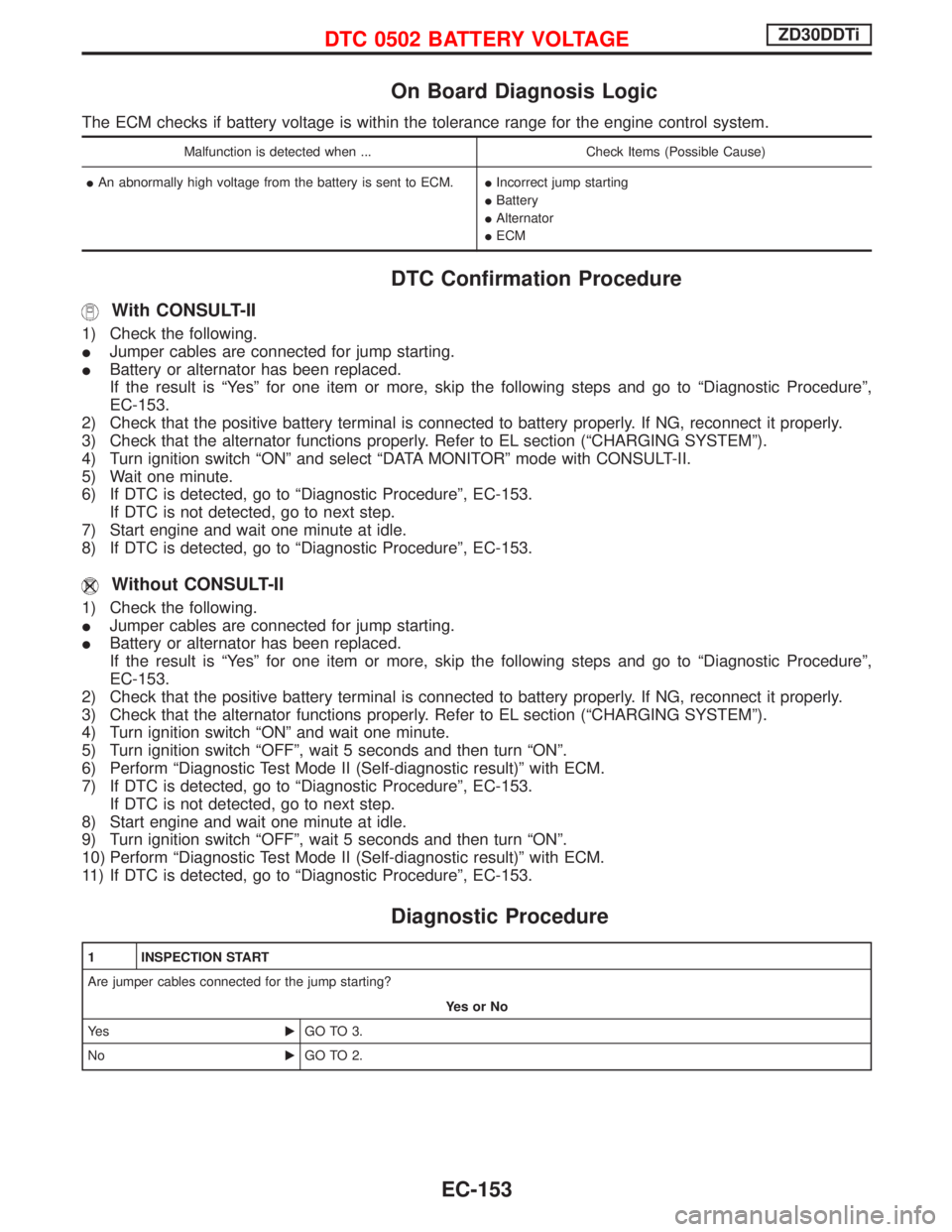
1 INSPECTION START
Are jumper cables connected for the jump starting?
YesorNo
Ye sEGO TO 3.
NoEGO TO 2.
DTC 0502 BATTERY VOLTAGEZD30DDTi
EC-153
Page 516 of 1767
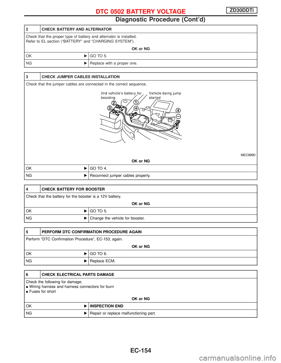
2 CHECK BATTERY AND ALTERNATOR
Check that the proper type of battery and alternator is installed.
Refer to EL section (ªBATTERYº and ªCHARGING SYSTEMº).
OK or NG
OKEGO TO 5.
NGEReplace with a proper one.
3 CHECK JUMPER CABLES INSTALLATION
Check that the jumper cables are connected in the correct sequence.
MEC999D
OK or NG
OKEGO TO 4.
NGEReconnect jumper cables properly.
4 CHECK BATTERY FOR BOOSTER
Check that the battery for the booster is a 12V battery.
OK or NG
OKEGO TO 5.
NGEChange the vehicle for booster.
5 PERFORM DTC CONFIRMATION PROCEDURE AGAIN
Perform ªDTC Confirmation Procedureº, EC-153, again.
OK or NG
OKEGO TO 6.
NGEReplace ECM.
6 CHECK ELECTRICAL PARTS DAMAGE
Check the following for damage.
IWiring harness and harness connectors for burn
IFuses for short
OK or NG
OKEINSPECTION END
NGERepair or replace malfunctioning part.
DTC 0502 BATTERY VOLTAGEZD30DDTi
Diagnostic Procedure (Cont'd)
EC-154
Page 1107 of 1767
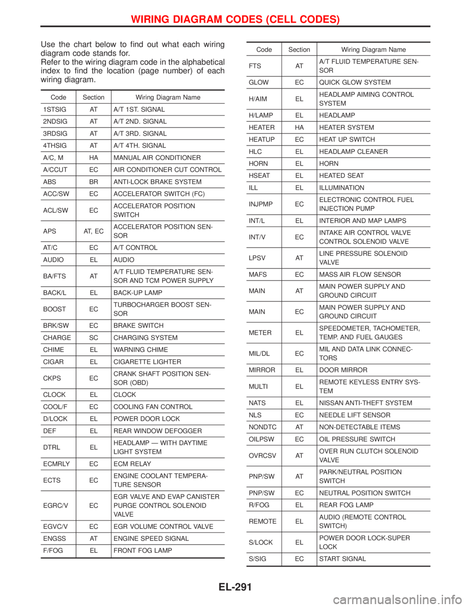
Use the chart below to find out what each wiring
diagram code stands for.
Refer to the wiring diagram code in the alphabetical
index to find the location (page number) of each
wiring diagram.
Code Section Wiring Diagram Name
1STSIG AT A/T 1ST. SIGNAL
2NDSIG AT A/T 2ND. SIGNAL
3RDSIG AT A/T 3RD. SIGNAL
4THSIG AT A/T 4TH. SIGNAL
A/C, M HA MANUAL AIR CONDITIONER
A/CCUT EC AIR CONDITIONER CUT CONTROL
ABS BR ANTI-LOCK BRAKE SYSTEM
ACC/SW EC ACCELERATOR SWITCH (FC)
ACL/SW ECACCELERATOR POSITION
SWITCH
APS AT, ECACCELERATOR POSITION SEN-
SOR
AT/C EC A/T CONTROL
AUDIO EL AUDIO
BA/FTS ATA/T FLUID TEMPERATURE SEN-
SOR AND TCM POWER SUPPLY
BACK/L EL BACK-UP LAMP
BOOST ECTURBOCHARGER BOOST SEN-
SOR
BRK/SW EC BRAKE SWITCH
CHARGE SC CHARGING SYSTEM
CHIME EL WARNING CHIME
CIGAR EL CIGARETTE LIGHTER
CKPS ECCRANK SHAFT POSITION SEN-
SOR (OBD)
CLOCK EL CLOCK
COOL/F EC COOLING FAN CONTROL
D/LOCK EL POWER DOOR LOCK
DEF EL REAR WINDOW DEFOGGER
DTRL ELHEADLAMP Ð WITH DAYTIME
LIGHT SYSTEM
ECMRLY EC ECM RELAY
ECTS ECENGINE COOLANT TEMPERA-
TURE SENSOR
EGRC/V ECEGR VALVE AND EVAP CANISTER
PURGE CONTROL SOLENOID
VA LV E
EGVC/V EC EGR VOLUME CONTROL VALVE
ENGSS AT ENGINE SPEED SIGNAL
F/FOG EL FRONT FOG LAMP
Code Section Wiring Diagram Name
FTS ATA/T FLUID TEMPERATURE SEN-
SOR
GLOW EC QUICK GLOW SYSTEM
H/AIM ELHEADLAMP AIMING CONTROL
SYSTEM
H/LAMP EL HEADLAMP
HEATER HA HEATER SYSTEM
HEATUP EC HEAT UP SWITCH
HLC EL HEADLAMP CLEANER
HORN EL HORN
HSEAT EL HEATED SEAT
ILL EL ILLUMINATION
INJPMP ECELECTRONIC CONTROL FUEL
INJECTION PUMP
INT/L EL INTERIOR AND MAP LAMPS
INT/V ECINTAKE AIR CONTROL VALVE
CONTROL SOLENOID VALVE
LPSV ATLINE PRESSURE SOLENOID
VA LV E
MAFS EC MASS AIR FLOW SENSOR
MAIN ATMAIN POWER SUPPLY AND
GROUND CIRCUIT
MAIN ECMAIN POWER SUPPLY AND
GROUND CIRCUIT
METER ELSPEEDOMETER, TACHOMETER,
TEMP. AND FUEL GAUGES
MIL/DL ECMIL AND DATA LINK CONNEC-
TORS
MIRROR EL DOOR MIRROR
MULTI ELREMOTE KEYLESS ENTRY SYS-
TEM
NATS EL NISSAN ANTI-THEFT SYSTEM
NLS EC NEEDLE LIFT SENSOR
NONDTC AT NON-DETECTABLE ITEMS
OILPSW EC OIL PRESSURE SWITCH
OVRCSV ATOVER RUN CLUTCH SOLENOID
VA LV E
PNP/SW ATPARK/NEUTRAL POSITION
SWITCH
PNP/SW EC NEUTRAL POSITION SWITCH
R/FOG EL REAR FOG LAMP
REMOTE ELAUDIO (REMOTE CONTROL
SWITCH)
S/LOCK ELPOWER DOOR LOCK-SUPER
LOCK
S/SIG EC START SIGNAL
WIRING DIAGRAM CODES (CELL CODES)
EL-291
Page 1357 of 1767
Precautions for Refrigerant Connection
WARNING:
Make sure all refrigerant is discharged into the recycling equipment and the pressure in the system
is less than atmospheric. Then gradually loosen the discharge side hose fitting and remove it.
CAUTION:
When replacing or cleaning refrigerant cycle components, observe the following.
IDo not leave compressor on its side or upside down for more than 10 minutes, as compressor oil
will enter low pressure chamber.
IWhen connecting tubes, always use a torque wrench and a back-up wrench.
IAfter disconnecting tubes, plug all openings immediately to prevent entrance of dirt and moisture.
IWhen installing an air conditioner in the vehicle, the pipes must be connected at the final stage of
the operation. The seal caps of the pipes and other components must not be removed until their
removal is required for connection.
ITo prevent the condensation of moisture inside A/C components, components stored in cool areas
should be allowed to warm to the working area temperature before removing the seal caps.
IThoroughly remove moisture from the refrigeration system before charging the refrigerant.
IAlways replace used O-rings.
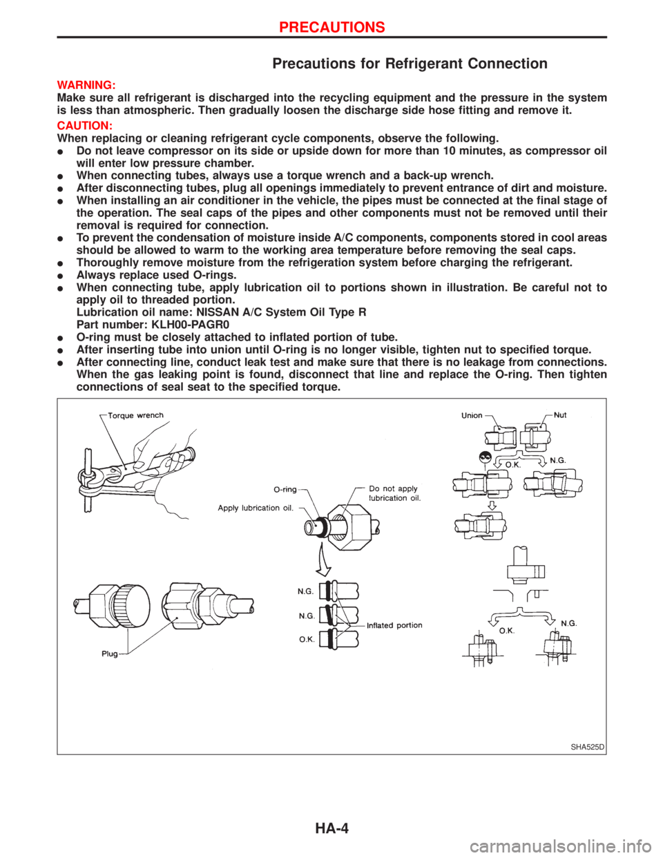
IWhen connecting tube, apply lubrication oil to portions shown in illustration. Be careful not to
apply oil to threaded portion.
Lubrication oil name: NISSAN A/C System Oil Type R
Part number: KLH00-PAGR0
IO-ring must be closely attached to inflated portion of tube.
IAfter inserting tube into union until O-ring is no longer visible, tighten nut to specified torque.
IAfter connecting line, conduct leak test and make sure that there is no leakage from connections.
When the gas leaking point is found, disconnect that line and replace the O-ring. Then tighten
connections of seal seat to the specified torque.
SHA525D
PRECAUTIONS
HA-4
Page 1364 of 1767
HFC-134a (R-134a) Service Tools and
Equipment
It is important to understand that HFC-134a (R-134a) refrigerant, and the specified lubricant which must be
used with HFC-134a (R-134a), must never be mixed with CFC-12 (R-12) refrigerant and/or the CFC-12 (R-12)
lubricant.
This means that separate and non-interchangeable service equipment must be used for handling each type
of refrigerant/lubricant.
To prevent the mixing of refrigerants/lubricants, refrigerant container fittings, service hose fittings, and service
equipment fittings (equipment which handles refrigerant and/or lubricant) are different between CFC-12 (R-12)
and HFC-134a (R-134a).
Adaptors to convert from one size of fitting to another must never be used: refrigerant/lubricant contamination
will occur and compressor failure will result.
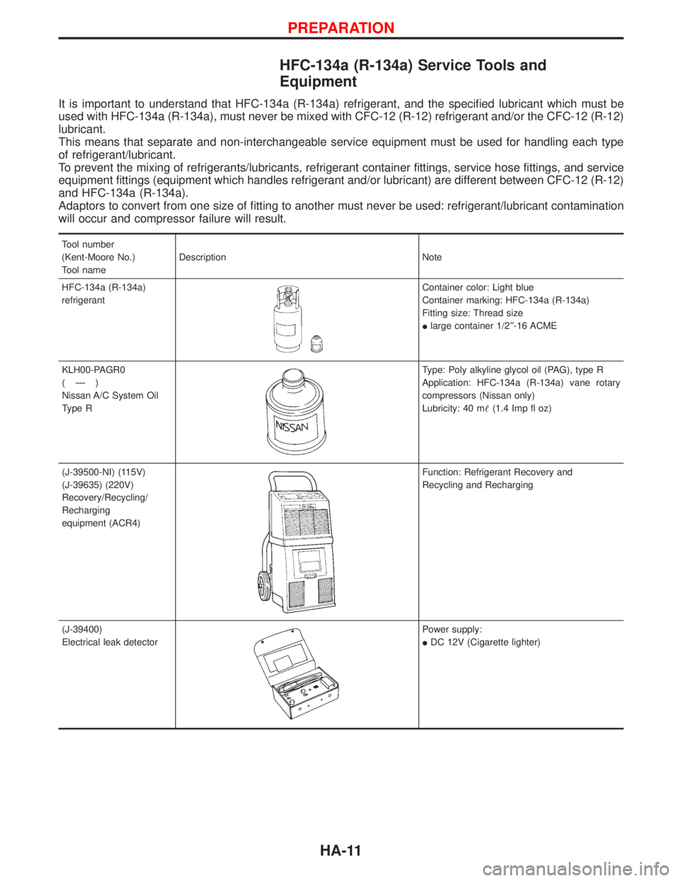
Tool number
(Kent-Moore No.)
Tool nameDescription Note
HFC-134a (R-134a)
refrigerant
Container color: Light blue
Container marking: HFC-134a (R-134a)
Fitting size: Thread size
Ilarge container 1/2²-16 ACME
KLH00-PAGR0
(Ð)
Nissan A/C System Oil
Type R
Type: Poly alkyline glycol oil (PAG), type R
Application: HFC-134a (R-134a) vane rotary
compressors (Nissan only)
Lubricity: 40 m(1.4 Imp fl oz)
(J-39500-NI) (115V)
(J-39635) (220V)
Recovery/Recycling/
Recharging
equipment (ACR4)
Function: Refrigerant Recovery and
Recycling and Recharging
(J-39400)
Electrical leak detector
Power supply:
IDC 12V (Cigarette lighter)
PREPARATION
HA-11
Page 1366 of 1767
Precautions for Service Equipment
RECOVERY/RECYCLING/RECHARGING EQUIPMENT
Be certain to follow the manufacturers instructions for machine
operation and machine maintenance. Never introduce any refriger-
ant other than that specified into the machine.
ELECTRONIC LEAK DETECTOR
Be certain to follow the manufactures instructions for tester opera-
tion and tester maintenance.
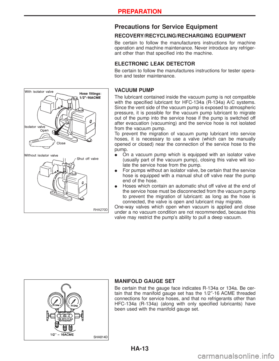
VACUUM PUMP
The lubricant contained inside the vacuum pump is not compatible
with the specified lubricant for HFC-134a (R-134a) A/C systems.
Since the vent side of the vacuum pump is exposed to atmospheric
pressure, it is possible for the vacuum pump lubricant to migrate
out of the pump into the service hose if the pump is switched off
after evacuation (vacuuming) and the service hose is not isolated
from the vacuum pump.
To prevent the migration of vacuum pump lubricant into service
hoses, it is necessary to use a valve (which can be manually
opened or closed) near the connection of the service hose to the
pump.
IOn a vacuum pump which is equipped with an isolator valve
(usually part of the vacuum pump), closing this valve will iso-
late the service hose from the pump.
IFor pumps without an isolator valve, be certain that the service
hose is equipped with a manual shut off valve near the pump
end of the hose.
IHoses which contain an automatic shut off valve at the end of
the service hose must be disconnected from the vacuum pump
to prevent the migration of lubricant: as long as the hose is
connected, the valve is open and lubricant may migrate.
One-way valves which open when vacuum is applied and close
under a no vacuum condition are not recommended, because this
valve may restrict the pump's ability to pull a deep vacuum.
MANIFOLD GAUGE SET
Be certain that the gauge face indicates R-134a or 134a. Be cer-
tain that the manifold gauge set has the 1/2²-16 ACME threaded
connections for service hoses, and that no refrigerants other than
HFC-134a (R-134a) (along with only specified lubricants) have
been used with the manifold gauge set.
RHA270D
SHA814D
PREPARATION
HA-13
Page 1367 of 1767
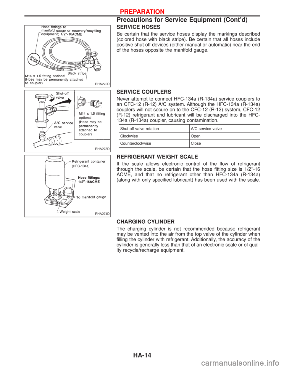
SERVICE HOSES
Be certain that the service hoses display the markings described
(colored hose with black stripe). Be certain that all hoses include
positive shut off devices (either manual or automatic) near the end
of the hoses opposite the manifold gauge.
SERVICE COUPLERS
Never attempt to connect HFC-134a (R-134a) service couplers to
an CFC-12 (R-12) A/C system. Although the HFC-134a (R-134a)
couplers will not secure on to the CFC-12 (R-12) system, CFC-12
(R-12) refrigerant and lubricant will be discharged into the HFC-
134a (R-134a) coupler, causing contamination.
Shut off valve rotation A/C service valve
Clockwise Open
Counterclockwise Close
REFRIGERANT WEIGHT SCALE
If the scale allows electronic control of the flow of refrigerant
through the scale, be certain that the hose fitting size is 1/2²-16
ACME, and that no refrigerant other than HFC-134a (R-134a)
(along with only specified lubricant) has been used with the scale.
CHARGING CYLINDER
The charging cylinder is not recommended because refrigerant
may be vented into the air from the top valve of the cylinder when
filling the cylinder with refrigerant. Additionally, the accuracy of the
cylinder is generally less than that of an electronic scale or of qual-
ity recycle/recharge equipment.
RHA272D
RHA273D
RHA274D
PREPARATION
Precautions for Service Equipment (Cont'd)
HA-14