fuel tank removal NISSAN TERRANO 2002 Service Repair Manual
[x] Cancel search | Manufacturer: NISSAN, Model Year: 2002, Model line: TERRANO, Model: NISSAN TERRANO 2002Pages: 1767, PDF Size: 41.51 MB
Page 859 of 1767
Bulb Replacement
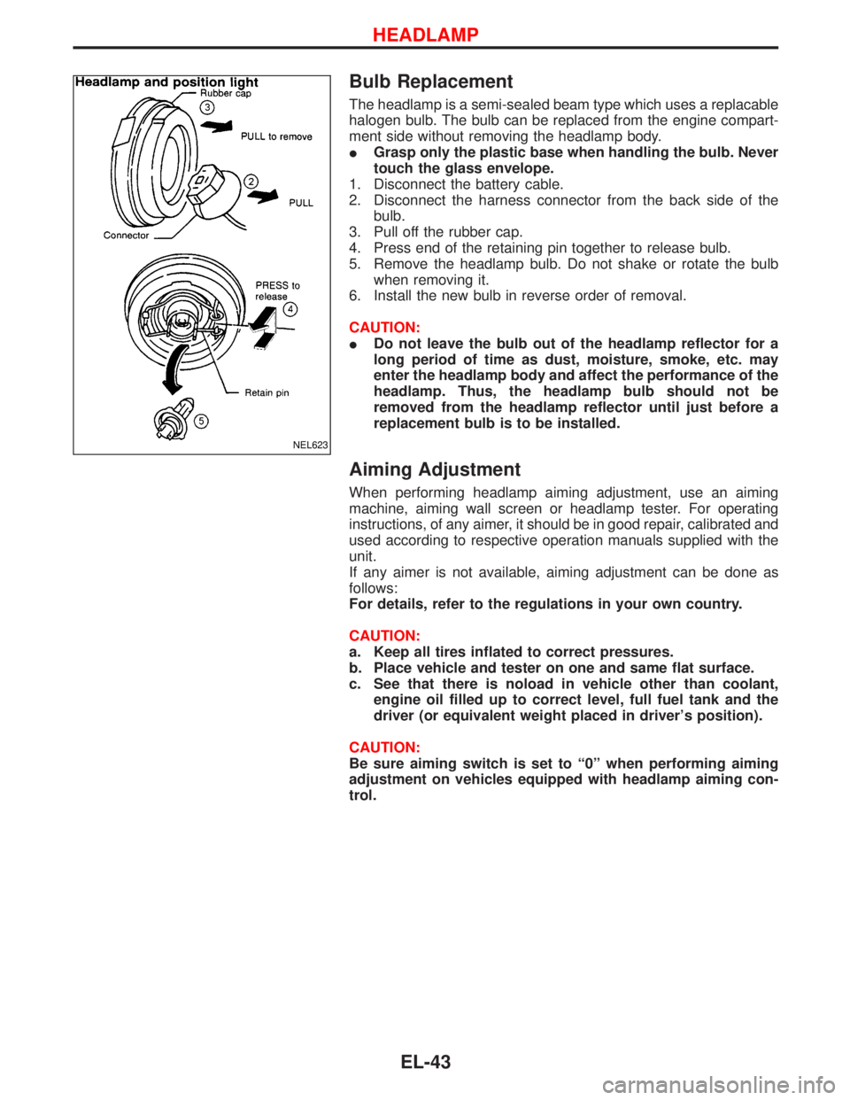
The headlamp is a semi-sealed beam type which uses a replacable
halogen bulb. The bulb can be replaced from the engine compart-
ment side without removing the headlamp body.
IGrasp only the plastic base when handling the bulb. Never
touch the glass envelope.
1. Disconnect the battery cable.
2. Disconnect the harness connector from the back side of the
bulb.
3. Pull off the rubber cap.
4. Press end of the retaining pin together to release bulb.
5. Remove the headlamp bulb. Do not shake or rotate the bulb
when removing it.
6. Install the new bulb in reverse order of removal.
CAUTION:
IDo not leave the bulb out of the headlamp reflector for a
long period of time as dust, moisture, smoke, etc. may
enter the headlamp body and affect the performance of the
headlamp. Thus, the headlamp bulb should not be
removed from the headlamp reflector until just before a
replacement bulb is to be installed.
Aiming Adjustment
When performing headlamp aiming adjustment, use an aiming
machine, aiming wall screen or headlamp tester. For operating
instructions, of any aimer, it should be in good repair, calibrated and
used according to respective operation manuals supplied with the
unit.
If any aimer is not available, aiming adjustment can be done as
follows:
For details, refer to the regulations in your own country.
CAUTION:
a. Keep all tires inflated to correct pressures.
b. Place vehicle and tester on one and same flat surface.
c. See that there is noload in vehicle other than coolant,
engine oil filled up to correct level, full fuel tank and the
driver (or equivalent weight placed in driver's position).
CAUTION:
Be sure aiming switch is set to ª0º when performing aiming
adjustment on vehicles equipped with headlamp aiming con-
trol.
NEL623
HEADLAMP
EL-43
Page 896 of 1767
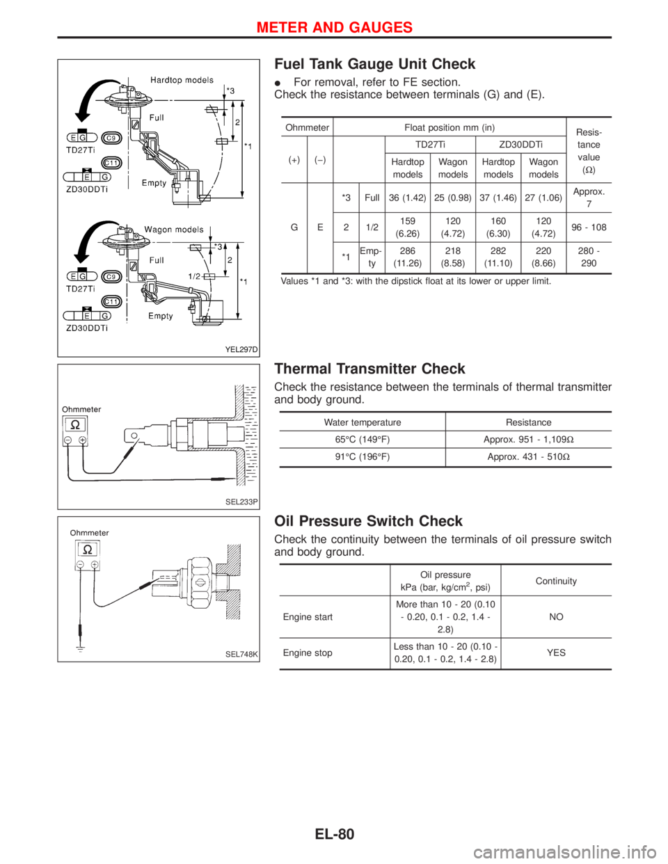
Fuel Tank Gauge Unit Check
IFor removal, refer to FE section.
Check the resistance between terminals (G) and (E).
Ohmmeter Float position mm (in)
Resis-
tance
value
(W) (+) (þ)TD27Ti ZD30DDTi
Hardtop
modelsWagon
modelsHardtop
modelsWagon
models
GE*3 Full 36 (1.42) 25 (0.98) 37 (1.46) 27 (1.06)Approx.
7
2 1/2159
(6.26)120
(4.72)160
(6.30)120
(4.72)96 - 108
*1Emp-
ty286
(11.26)218
(8.58)282
(11.10)220
(8.66)280 -
290
Values *1 and *3: with the dipstick float at its lower or upper limit.
Thermal Transmitter Check
Check the resistance between the terminals of thermal transmitter
and body ground.
Water temperature Resistance
65ÉC (149ÉF) Approx. 951 - 1,109W
91ÉC (196ÉF) Approx. 431 - 510W
Oil Pressure Switch Check
Check the continuity between the terminals of oil pressure switch
and body ground.
Oil pressure
kPa (bar, kg/cm2, psi)Continuity
Engine startMore than 10 - 20 (0.10
- 0.20, 0.1 - 0.2, 1.4 -
2.8)NO
Engine stopLess than 10 - 20 (0.10 -
0.20, 0.1 - 0.2, 1.4 - 2.8)YES
YEL297D
SEL233P
SEL748K
METER AND GAUGES
EL-80
Page 1172 of 1767
Engine room (Left)
3. Remove air duct and air cleaner case.
4. Disconnect vacuum hose to the vehicle on the engine.
5. Disconnect harness connectors from alternator and air com-
pressor.
6. Remove alternator.
7. After removing refrigerant, remove pipes of air compressor and
inlet/outlet.
8. Disconnect heating hose, install blank cap to hose to prevent
coolant from leaking.
9. Remove heating pipe.
10. Remove heat insulator.
11. Remove catalytic converter.
Engine room (Right)
12. Remove power steering reservoir tank from bracket, and fix it
to the vehicle with a rope.
CAUTION:
Keep the reservoir tank level when fixing to prevent oil leak.
13. Remove fuel feed and return hoses.
CAUTION:
Install blank caps immediately to avoid fuel leakage.
14. Remove all harness connectors on the engine, and move har-
nesses to the side of the vehicle.
Vehicle underfloor
15. Remove starter motor.
16. Detach A/T oil cooler pipes from oil pan. (A/T model)
17. Remove rear propeller shaft.
18. Remove mounting bolts to secure the engine to transmission.
1) Remove torque converter installation bolt. (A/T model)
2) Lift transmission bottom with transmission jack, and remove
rear mount members from the vehicle.
3) Lower transmission with the jack, and remove upper mounting
bolts securing the engine to transmission.
4) Lift transmission with the jack, and reinstall rear mount mem-
bers to the vehicle.
5) Position the jack to the front side of transmission.
6) Remove remaining mounting bolts securing the engine to trans-
mission.
Removal operation
19. Remove air conditioner high pressure pipes at the rear of the
engine room.
IThis is due to some inconvenience in the rear slinger installa-
tion.
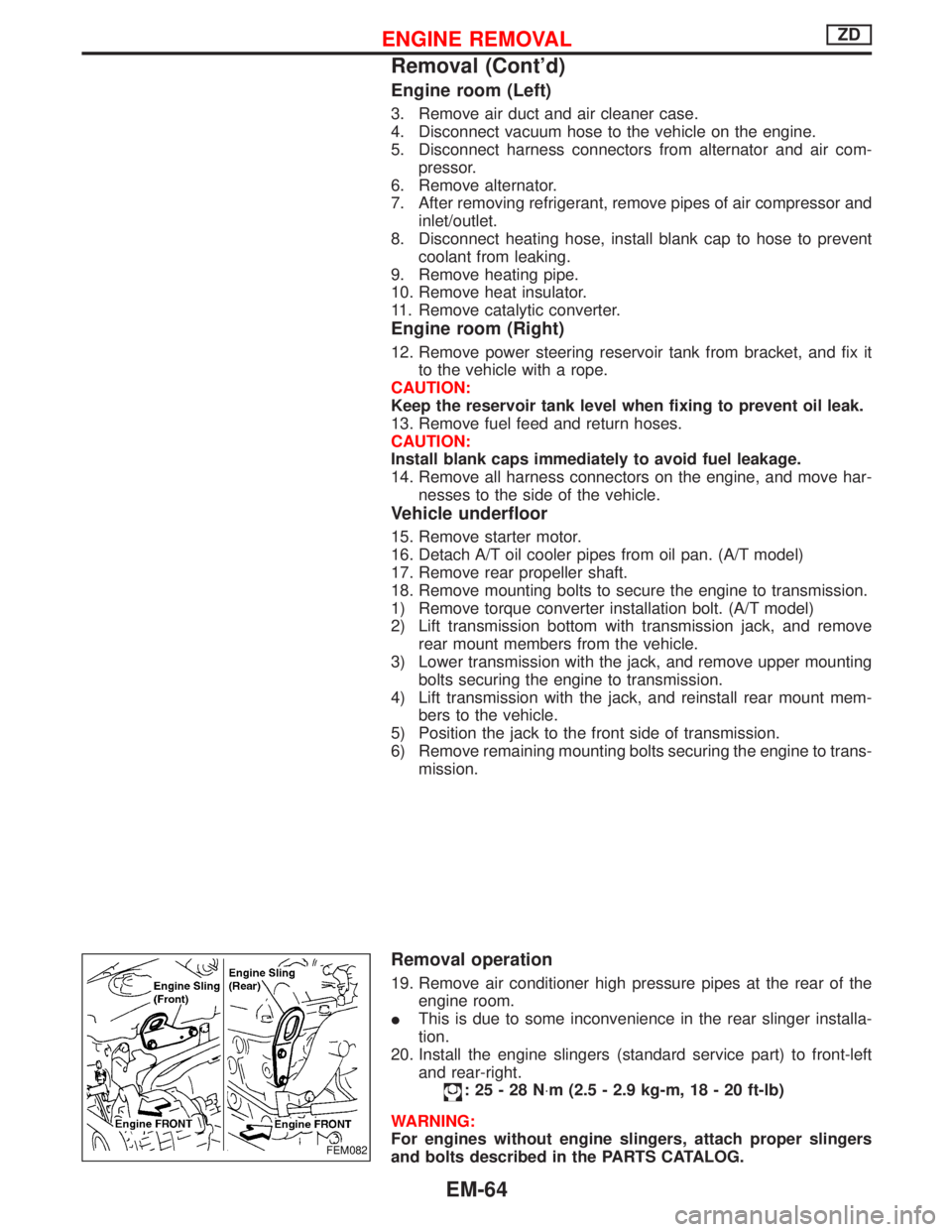
20. Install the engine slingers (standard service part) to front-left
and rear-right.
:25-28N×m (2.5 - 2.9 kg-m, 18 - 20 ft-lb)
WARNING:
For engines without engine slingers, attach proper slingers
and bolts described in the PARTS CATALOG.
FEM082
ENGINE REMOVALZD
Removal (Cont'd)
EM-64
Page 1306 of 1767
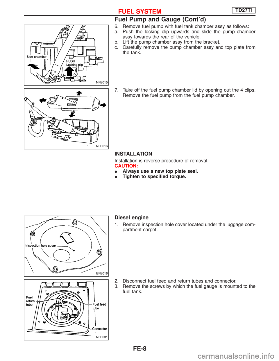
6. Remove fuel pump with fuel tank chamber assy as follows:
a. Push the locking clip upwards and slide the pump chamber
assy towards the rear of the vehicle.
b. Lift the pump chamber assy from the bracket.
c. Carefully remove the pump chamber assy and top plate from
the tank.
7. Take off the fuel pump chamber lid by opening out the 4 clips.
Remove the fuel pump from the fuel pump chamber.
INSTALLATION
Installation is reverse procedure of removal.
CAUTION:
IAlways use a new top plate seal.
ITighten to specified torque.
Diesel engine
1. Remove inspection hole cover located under the luggage com-
partment carpet.
2. Disconnect fuel feed and return tubes and connector.
3. Remove the screws by which the fuel gauge is mounted to the
fuel tank.
NFE015
NFE016
EFE016
NFE031
FUEL SYSTEMTD27Ti
Fuel Pump and Gauge (Cont'd)
FE-8
Page 1421 of 1767
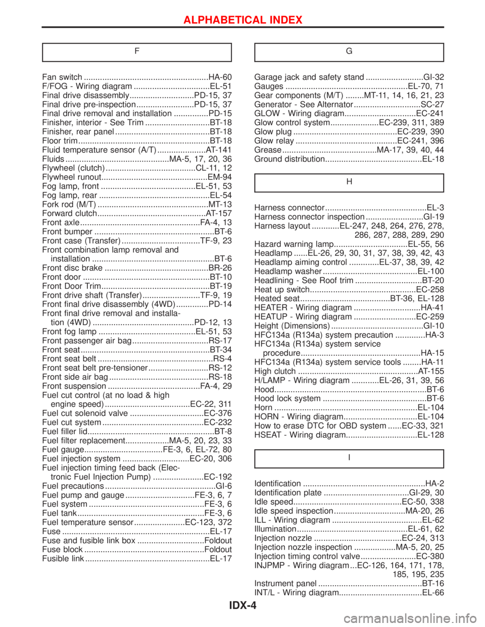
F
Fan switch ......................................................HA-60
F/FOG - Wiring diagram .................................EL-51
Final drive disassembly............................PD-15, 37
Final drive pre-inspection .........................PD-15, 37
Final drive removal and installation ...............PD-15
Finisher, interior - See Trim ............................BT-18
Finisher, rear panel .........................................BT-18
Floor trim .........................................................BT-18
Fluid temperature sensor (A/T) .....................AT-141
Fluids .............................................MA-5, 17, 20, 36
Flywheel (clutch) .......................................CL-11, 12
Flywheel runout..............................................EM-94
Fog lamp, front .........................................EL-51, 53
Fog lamp, rear ................................................EL-54
Fork rod (M/T) ................................................MT-13
Forward clutch...............................................AT-157
Front axle ....................................................FA-4, 13
Front bumper ....................................................BT-6
Front case (Transfer) ..................................TF-9, 23
Front combination lamp removal and
installation .....................................................BT-6
Front disc brake .............................................BR-26
Front door .......................................................BT-10
Front Door Trim...............................................BT-19
Front drive shaft (Transfer) .........................TF-9, 19
Front final drive disassembly (4WD) ..............PD-14
Front final drive removal and installa-
tion (4WD) ............................................PD-12, 13
Front fog lamp ..........................................EL-51, 53
Front passenger air bag .................................RS-17
Front seat ........................................................BT-34
Front seat belt ..................................................RS-4
Front seat belt pre-tensioner ..........................RS-12
Front side air bag ...........................................RS-18
Front suspension ........................................FA-4, 29
Fuel cut control (at no load & high
engine speed) .....................................EC-22, 311
Fuel cut solenoid valve ................................EC-376
Fuel cut system ............................................EC-232
Fuel filler lid.......................................................BT-8
Fuel filter replacement...................MA-5, 20, 23, 33
Fuel gauge..................................FE-3, 6, EL-72, 80
Fuel injection system .............................EC-20, 306
Fuel injection timing feed back (Elec-
tronic Fuel Injection Pump) ......................EC-192
Fuel precautions ................................................GI-6
Fuel pump and gauge ..............................FE-3, 6, 7
Fuel system ..................................................FE-3, 6
Fuel tank .......................................................FE-3, 6
Fuel temperature sensor ......................EC-123, 372
Fuse ................................................................EL-17
Fuse and fusible link box .............................Foldout
Fuse block ....................................................Foldout
Fusible link ......................................................EL-17GGarage jack and safety stand .........................GI-32
Gauges .....................................................EL-70, 71
Gear components (M/T) ........MT-11, 14, 16, 21, 23
Generator - See Alternator .............................SC-27
GLOW - Wiring diagram...............................EC-241
Glow control system.....................EC-239, 311, 389
Glow plug .............................................EC-239, 390
Glow relay ............................................EC-241, 396
Grease .........................................MA-17, 39, 40, 44
Ground distribution..........................................EL-18
H
Harness connector ............................................EL-3
Harness connector inspection .........................GI-19
Harness layout ............EL-247, 248, 264, 276, 278,
286, 287, 288, 289, 290
Hazard warning lamp................................EL-55, 56
Headlamp ......EL-26, 29, 30, 31, 37, 38, 39, 42, 43
Headlamp aiming control .............EL-37, 38, 39, 42
Headlamp washer .........................................EL-100
Headlining - See Roof trim .............................BT-20
Heat up switch..............................................EC-258
Heated seat .......................................BT-36, EL-128
HEATER - Wiring diagram .............................HA-41
HEATUP - Wiring diagram ...........................EC-259
Height (Dimensions) ........................................GI-10
HFC134a (R134a) system precaution .............HA-3
HFC134a (R134a) system service
procedure....................................................HA-15
HFC134a (R134a) system service tools ........HA-11
High clutch ....................................................AT-155
H/LAMP - Wiring diagram ............EL-26, 31, 39, 56
Hood..................................................................BT-6
Hood lock system .............................................BT-6
Horn ..............................................................EL-104
HORN - Wiring diagram................................EL-104
How to erase DTC for OBD system ......EC-33, 321
HSEAT - Wiring diagram...............................EL-128
I
Identification .....................................................HA-2
Identification plate .....................................GI-29, 30
Idle speed...............................................EC-50, 338
Idle speed inspection ...............................MA-20, 26
ILL - Wiring diagram .......................................EL-62
Illumination ................................................EL-61, 62
Injection nozzle ......................................EC-24, 313
Injection nozzle inspection ..................MA-5, 20, 25
Injection timing control valve ........................EC-380
INJPMP - Wiring diagram ...EC-126, 164, 171, 178,
185, 195, 235
Instrument panel .............................................BT-16
INT/L - Wiring diagram....................................EL-66
ALPHABETICAL INDEX
IDX-4