height NISSAN TERRANO 2002 Service Repair Manual
[x] Cancel search | Manufacturer: NISSAN, Model Year: 2002, Model line: TERRANO, Model: NISSAN TERRANO 2002Pages: 1767, PDF Size: 41.51 MB
Page 217 of 1767
Inspection
Check brake pedal for following items:
IBrake pedal bend
IClevis pin deformation
ICrack of any welded portion
ICrack or deformation of clevis pin stopper
Adjustment
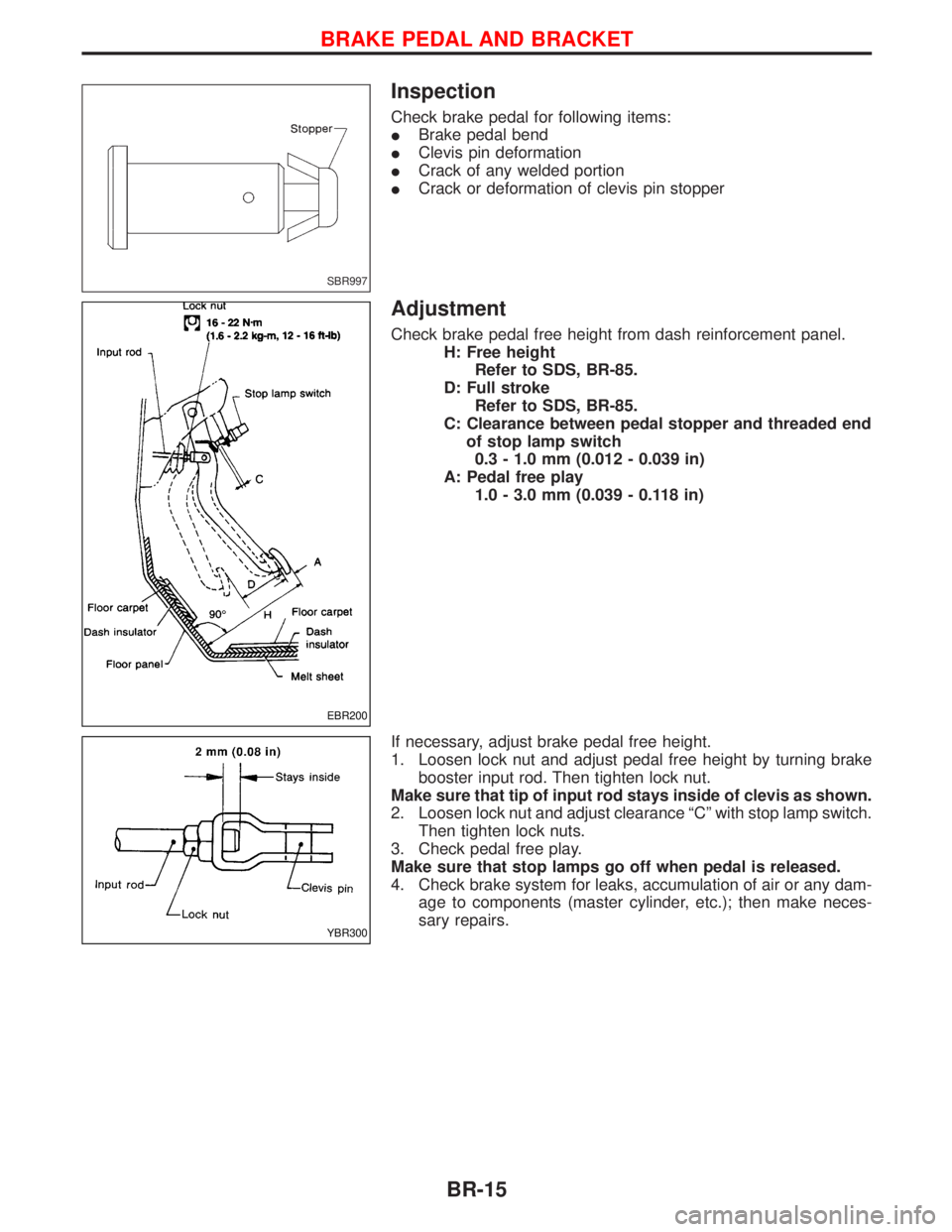
Check brake pedal free height from dash reinforcement panel.
H: Free height
Refer to SDS, BR-85.
D: Full stroke
Refer to SDS, BR-85.
C: Clearance between pedal stopper and threaded end
of stop lamp switch
0.3 - 1.0 mm (0.012 - 0.039 in)
A: Pedal free play
1.0 - 3.0 mm (0.039 - 0.118 in)
If necessary, adjust brake pedal free height.
1. Loosen lock nut and adjust pedal free height by turning brake
booster input rod. Then tighten lock nut.
Make sure that tip of input rod stays inside of clevis as shown.
2. Loosen lock nut and adjust clearance ªCº with stop lamp switch.
Then tighten lock nuts.
3. Check pedal free play.
Make sure that stop lamps go off when pedal is released.
4. Check brake system for leaks, accumulation of air or any dam-
age to components (master cylinder, etc.); then make neces-
sary repairs.
SBR997
EBR200
YBR300
BRAKE PEDAL AND BRACKET
BR-15
Page 287 of 1767
Inspection and Adjustment
DISC BRAKE
Unit: mm (in)
Brake model LD28VA
Pad wear limit
Minimum thickness 2.0 (0.079)
Rotor repair limit
Minimum thickness 24.0 (0.94)
DRUM BRAKE
Unit: mm (in)
Lining wear limit
Minimum thickness 1.52 (0.06)
Drum repair limit
Maximum inner diameter 280.5 (11.04)
Out-of-roundness0.05 (0.0020)
or less
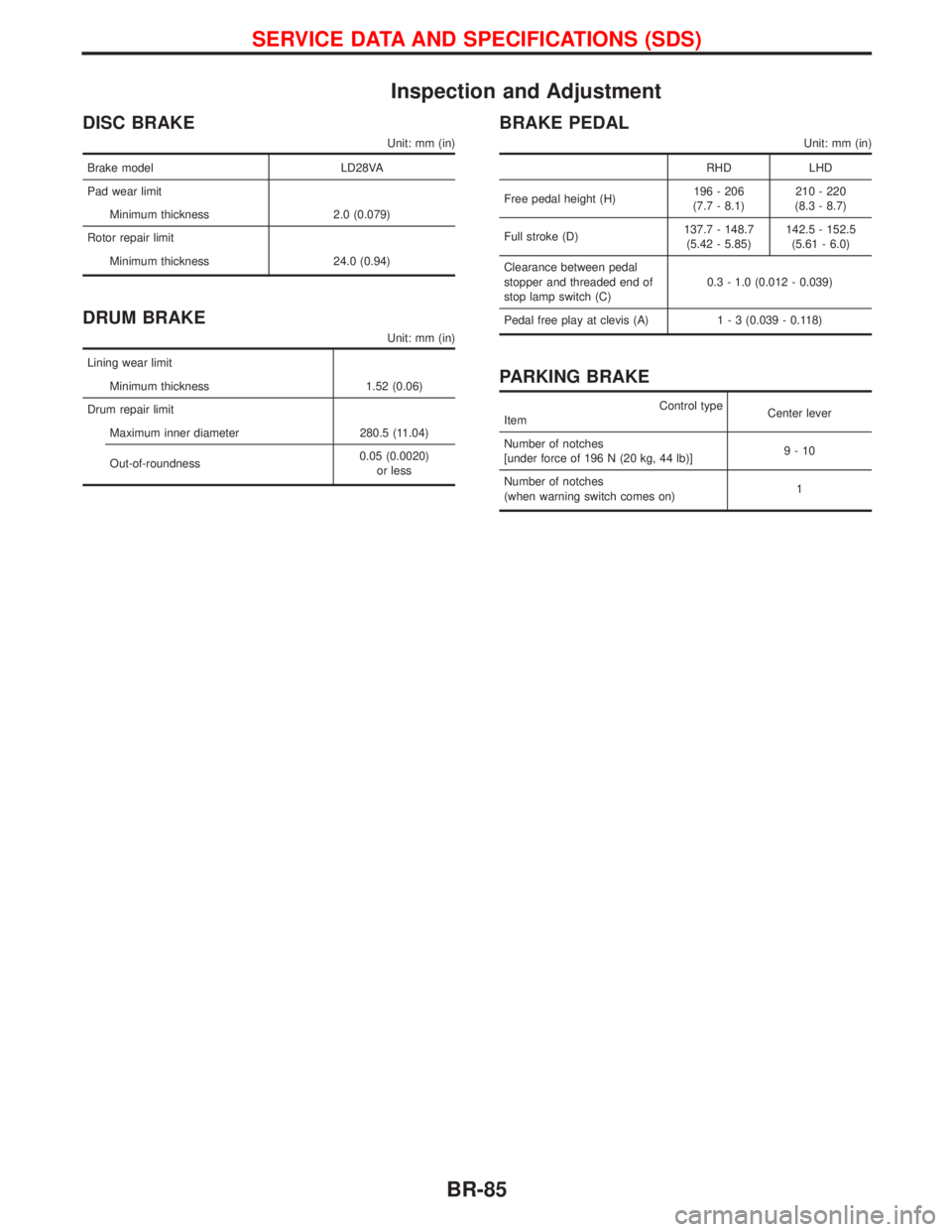
BRAKE PEDAL
Unit: mm (in)
RHD LHD
Free pedal height (H)196 - 206
(7.7 - 8.1)210 - 220
(8.3 - 8.7)
Full stroke (D)137.7 - 148.7
(5.42 - 5.85)142.5 - 152.5
(5.61 - 6.0)
Clearance between pedal
stopper and threaded end of
stop lamp switch (C)0.3 - 1.0 (0.012 - 0.039)
Pedal free play at clevis (A)1 - 3 (0.039 - 0.118)
PARKING BRAKE
Control type
ItemCenter lever
Number of notches
[under force of 196 N (20 kg, 44 lb)]9-10
Number of notches
(when warning switch comes on)1
SERVICE DATA AND SPECIFICATIONS (SDS)
BR-85
Page 353 of 1767
Adjusting Clutch Pedal
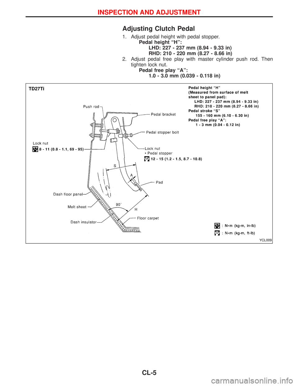
1. Adjust pedal height with pedal stopper.
Pedal height ªHº:
LHD: 227 - 237 mm (8.94 - 9.33 in)
RHD: 210 - 220 mm (8.27 - 8.66 in)
2. Adjust pedal free play with master cylinder push rod. Then
tighten lock nut.
Pedal free play ªAº:
1.0 - 3.0 mm (0.039 - 0.118 in)
YCL009
INSPECTION AND ADJUSTMENT
CL-5
Page 360 of 1767
Clutch Cover and Flywheel
INSPECTION AND ADJUSTMENT
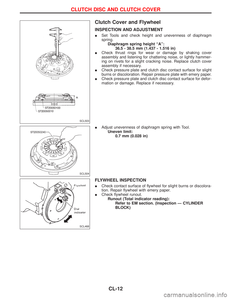
ISet Tools and check height and unevenness of diaphragm
spring.
Diaphragm spring height ªAº:
36.5 - 38.5 mm (1.437 - 1.516 in)
ICheck thrust rings for wear or damage by shaking cover
assembly and listening for chattering noise, or lightly hammer-
ing on rivets for a slight cracking noise. Replace clutch cover
assembly if necessary.
ICheck pressure plate and clutch disc contact surface for slight
burns or discoloration. Repair pressure plate with emery paper.
ICheck pressure plate and clutch disc contact surface for defor-
mation or damage. Replace if necessary.
IAdjust unevenness of diaphragm spring with Tool.
Uneven limit:
0.7 mm (0.028 in)
FLYWHEEL INSPECTION
ICheck contact surface of flywheel for slight burns or discolora-
tion. Repair flywheel with emery paper.
ICheck flywheel runout.
Runout (Total indicator reading):
Refer to EM section. (Inspection Ð CYLINDER
BLOCK)
SCL503
SCL504
SCL468
CLUTCH DISC AND CLUTCH COVER
CL-12
Page 362 of 1767
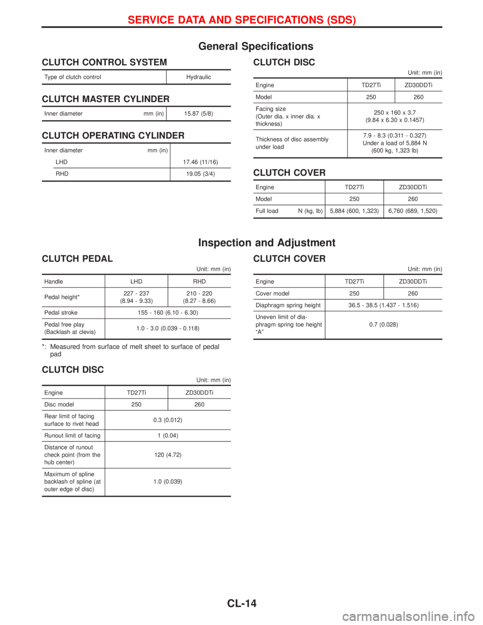
General Specifications
CLUTCH CONTROL SYSTEM
Type of clutch control Hydraulic
CLUTCH MASTER CYLINDER
Inner diameter mm (in) 15.87 (5/8)
CLUTCH OPERATING CYLINDER
Inner diameter mm (in)
LHD 17.46 (11/16)
RHD 19.05 (3/4)
CLUTCH DISC
Unit: mm (in)
Engine TD27Ti ZD30DDTi
Model 250 260
Facing size
(Outer dia. x inner dia. x
thickness)250 x 160 x 3.7
(9.84 x 6.30 x 0.1457)
Thickness of disc assembly
under load7.9 - 8.3 (0.311 - 0.327)
Under a load of 5,884 N
(600 kg, 1,323 lb)
CLUTCH COVER
Engine TD27Ti ZD30DDTi
Model 250 260
Full load N (kg, lb) 5,884 (600, 1,323) 6,760 (689, 1,520)
Inspection and Adjustment
CLUTCH PEDAL
Unit: mm (in)
Handle LHD RHD
Pedal height*227 - 237
(8.94 - 9.33)210 - 220
(8.27 - 8.66)
Pedal stroke 155 - 160 (6.10 - 6.30)
Pedal free play
(Backlash at clevis)1.0 - 3.0 (0.039 - 0.118)
*: Measured from surface of melt sheet to surface of pedal
pad
CLUTCH DISC
Unit: mm (in)
Engine TD27Ti ZD30DDTi
Disc model 250 260
Rear limit of facing
surface to rivet head0.3 (0.012)
Runout limit of facing 1 (0.04)
Distance of runout
check point (from the
hub center)120 (4.72)
Maximum of spline
backlash of spline (at
outer edge of disc)1.0 (0.039)
CLUTCH COVER
Unit: mm (in)
Engine TD27Ti ZD30DDTi
Cover model 250 260
Diaphragm spring height 36.5 - 38.5 (1.437 - 1.516)
Uneven limit of dia-
phragm spring toe height
ªAº0.7 (0.028)
SERVICE DATA AND SPECIFICATIONS (SDS)
CL-14
Page 609 of 1767
![NISSAN TERRANO 2002 Service Repair Manual 17 CHECK GLOW PLUG
1. Remove glow plug connecting plate.
2. Check glow plug resistance.
MEC005EResistance: Approx. 0.5W[at 20ÉC (68ÉF)]
NOTE:
IDo not bump glow plug heating element. If it is bumped, NISSAN TERRANO 2002 Service Repair Manual 17 CHECK GLOW PLUG
1. Remove glow plug connecting plate.
2. Check glow plug resistance.
MEC005EResistance: Approx. 0.5W[at 20ÉC (68ÉF)]
NOTE:
IDo not bump glow plug heating element. If it is bumped,](/img/5/57393/w960_57393-608.png)
17 CHECK GLOW PLUG
1. Remove glow plug connecting plate.
2. Check glow plug resistance.
MEC005EResistance: Approx. 0.5W[at 20ÉC (68ÉF)]
NOTE:
IDo not bump glow plug heating element. If it is bumped, replace glow plug with a new one.
IIf glow plug is dropped from a height of 10 cm (3.94 in) or higher, replace with a new one.
IIf glow plug installation hole is contaminated with carbon, remove it with a reamer or suitable tool.
IHand-tighten glow plug by turning it two or three times, then tighten using a tool to specified torque.
:15-20N×m (1.5 - 2.1 kg-m, 11 - 15 ft-lb)
OK or NG
OKEGO TO 18.
NGEReplace glow plug.
18 CHECK INTERMITTENT INCIDENT
Refer to ªTROUBLE DIAGNOSIS FOR INTERMITTENT INCIDENTº, EC-78.
EINSPECTION END
GLOW CONTROL SYSTEMZD30DDTi
Diagnostic Procedure (Cont'd)
EC-247
Page 758 of 1767
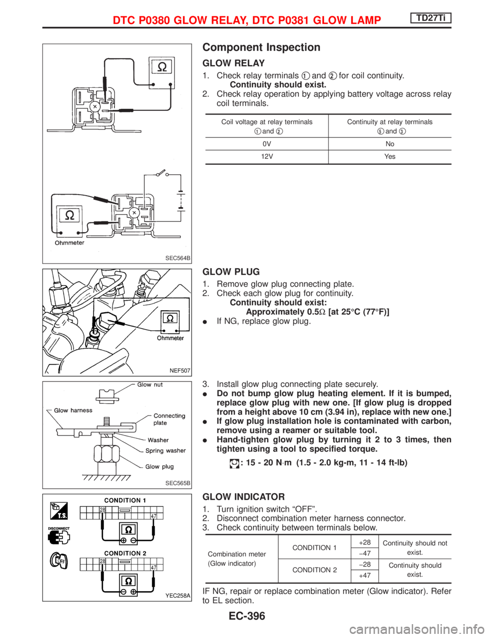
Component Inspection
GLOW RELAY
1. Check relay terminalsq1andq2for coil continuity.
Continuity should exist.
2. Check relay operation by applying battery voltage across relay
coil terminals.
Coil voltage at relay terminals
q
1andq2
Continuity at relay terminals
q
5andq3
0V No
12V Yes
GLOW PLUG
1. Remove glow plug connecting plate.
2. Check each glow plug for continuity.
Continuity should exist:
Approximately 0.5W[at 25ÉC (77ÉF)]
IIf NG, replace glow plug.
3. Install glow plug connecting plate securely.
IDo not bump glow plug heating element. If it is bumped,
replace glow plug with new one. [If glow plug is dropped
from a height above 10 cm (3.94 in), replace with new one.]
IIf glow plug installation hole is contaminated with carbon,
remove using a reamer or suitable tool.
IHand-tighten glow plug by turning it 2 to 3 times, then
tighten using a tool to specified torque.
:15-20N×m (1.5 - 2.0 kg-m, 11 - 14 ft-lb)
GLOW INDICATOR
1. Turn ignition switch ªOFFº.
2. Disconnect combination meter harness connector.
3. Check continuity between terminals below.
Combination meter
(Glow indicator)CONDITION 1+28
Continuity should not
exist.
þ47
CONDITION 2þ28
Continuity should
exist.
+47
IF NG, repair or replace combination meter (Glow indicator). Refer
to EL section.
SEC564B
NEF507
SEC565B
YEC258A
DTC P0380 GLOW RELAY, DTC P0381 GLOW LAMPTD27Ti
EC-396
Page 1139 of 1767
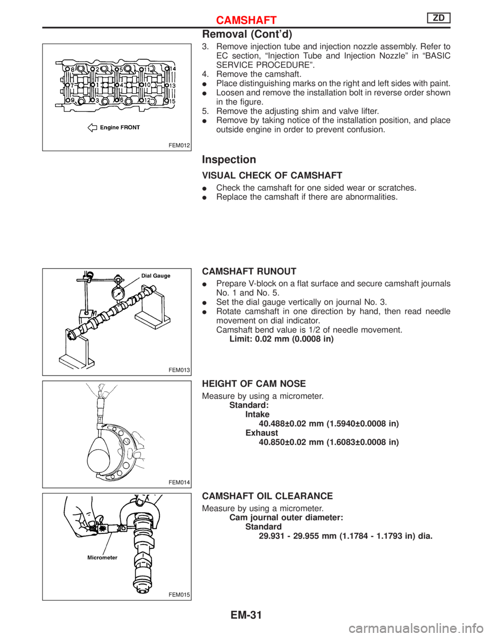
3. Remove injection tube and injection nozzle assembly. Refer to
EC section, ªInjection Tube and Injection Nozzleº in ªBASIC
SERVICE PROCEDUREº.
4. Remove the camshaft.
IPlace distinguishing marks on the right and left sides with paint.
ILoosen and remove the installation bolt in reverse order shown
in the figure.
5. Remove the adjusting shim and valve lifter.
IRemove by taking notice of the installation position, and place
outside engine in order to prevent confusion.
Inspection
VISUAL CHECK OF CAMSHAFT
ICheck the camshaft for one sided wear or scratches.
IReplace the camshaft if there are abnormalities.
CAMSHAFT RUNOUT
IPrepare V-block on a flat surface and secure camshaft journals
No. 1 and No. 5.
ISet the dial gauge vertically on journal No. 3.
IRotate camshaft in one direction by hand, then read needle
movement on dial indicator.
Camshaft bend value is 1/2 of needle movement.
Limit: 0.02 mm (0.0008 in)
HEIGHT OF CAM NOSE
Measure by using a micrometer.
Standard:
Intake
40.488 0.02 mm (1.5940 0.0008 in)
Exhaust
40.850 0.02 mm (1.6083 0.0008 in)
CAMSHAFT OIL CLEARANCE
Measure by using a micrometer.
Cam journal outer diameter:
Standard
29.931 - 29.955 mm (1.1784 - 1.1793 in) dia.
FEM012
FEM013
FEM014
FEM015
CAMSHAFTZD
Removal (Cont'd)
EM-31
Page 1161 of 1767
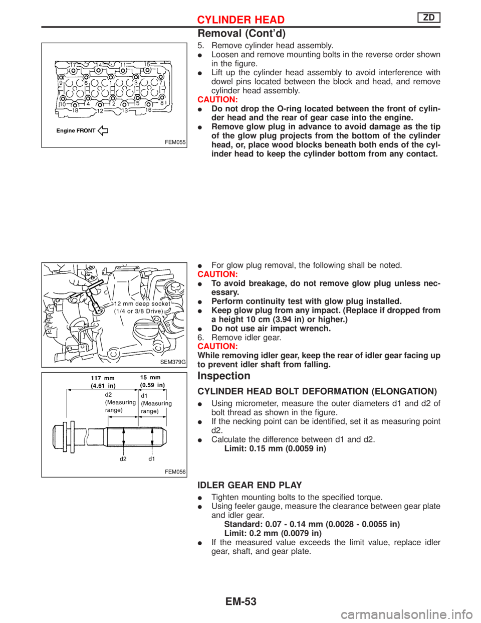
5. Remove cylinder head assembly.
ILoosen and remove mounting bolts in the reverse order shown
in the figure.
ILift up the cylinder head assembly to avoid interference with
dowel pins located between the block and head, and remove
cylinder head assembly.
CAUTION:
IDo not drop the O-ring located between the front of cylin-
der head and the rear of gear case into the engine.
IRemove glow plug in advance to avoid damage as the tip
of the glow plug projects from the bottom of the cylinder
head, or, place wood blocks beneath both ends of the cyl-
inder head to keep the cylinder bottom from any contact.
IFor glow plug removal, the following shall be noted.
CAUTION:
ITo avoid breakage, do not remove glow plug unless nec-
essary.
IPerform continuity test with glow plug installed.
IKeep glow plug from any impact. (Replace if dropped from
a height 10 cm (3.94 in) or higher.)
IDo not use air impact wrench.
6. Remove idler gear.
CAUTION:
While removing idler gear, keep the rear of idler gear facing up
to prevent idler shaft from falling.
Inspection
CYLINDER HEAD BOLT DEFORMATION (ELONGATION)
IUsing micrometer, measure the outer diameters d1 and d2 of
bolt thread as shown in the figure.
IIf the necking point can be identified, set it as measuring point
d2.
ICalculate the difference between d1 and d2.
Limit: 0.15 mm (0.0059 in)
IDLER GEAR END PLAY
ITighten mounting bolts to the specified torque.
IUsing feeler gauge, measure the clearance between gear plate
and idler gear.
Standard: 0.07 - 0.14 mm (0.0028 - 0.0055 in)
Limit: 0.2 mm (0.0079 in)
IIf the measured value exceeds the limit value, replace idler
gear, shaft, and gear plate.
FEM055
SEM379G
FEM056
CYLINDER HEADZD
Removal (Cont'd)
EM-53
Page 1162 of 1767
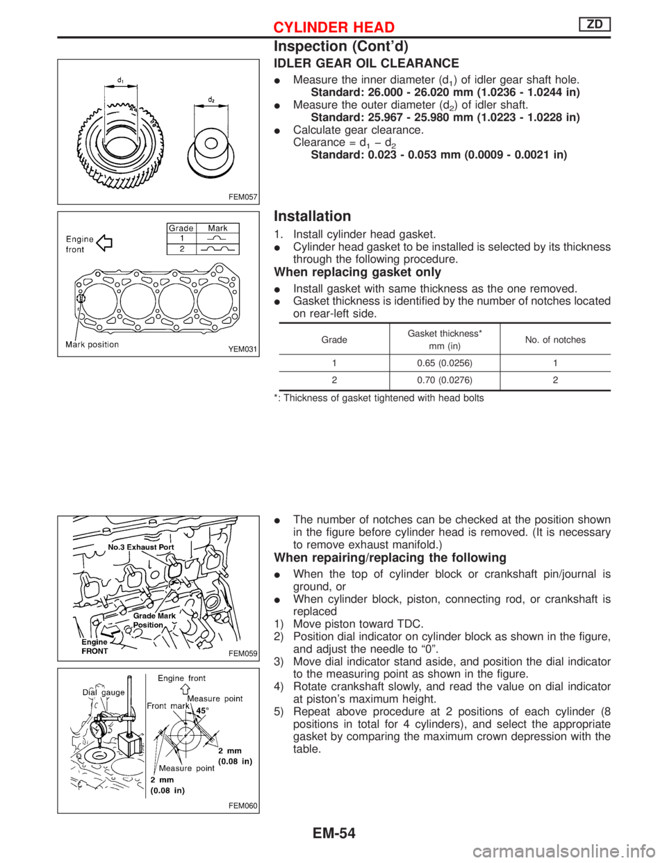
IDLER GEAR OIL CLEARANCE
IMeasure the inner diameter (d1) of idler gear shaft hole.
Standard: 26.000 - 26.020 mm (1.0236 - 1.0244 in)
IMeasure the outer diameter (d
2) of idler shaft.
Standard: 25.967 - 25.980 mm (1.0223 - 1.0228 in)
ICalculate gear clearance.
Clearance = d
1þd2Standard: 0.023 - 0.053 mm (0.0009 - 0.0021 in)
Installation
1. Install cylinder head gasket.
ICylinder head gasket to be installed is selected by its thickness
through the following procedure.
When replacing gasket only
IInstall gasket with same thickness as the one removed.
IGasket thickness is identified by the number of notches located
on rear-left side.
GradeGasket thickness*
mm (in)No. of notches
1 0.65 (0.0256) 1
2 0.70 (0.0276) 2
*: Thickness of gasket tightened with head bolts
IThe number of notches can be checked at the position shown
in the figure before cylinder head is removed. (It is necessary
to remove exhaust manifold.)
When repairing/replacing the following
IWhen the top of cylinder block or crankshaft pin/journal is
ground, or
IWhen cylinder block, piston, connecting rod, or crankshaft is
replaced
1) Move piston toward TDC.
2) Position dial indicator on cylinder block as shown in the figure,
and adjust the needle to ª0º.
3) Move dial indicator stand aside, and position the dial indicator
to the measuring point as shown in the figure.
4) Rotate crankshaft slowly, and read the value on dial indicator
at piston's maximum height.
5) Repeat above procedure at 2 positions of each cylinder (8
positions in total for 4 cylinders), and select the appropriate
gasket by comparing the maximum crown depression with the
table.
FEM057
YEM031
FEM059
FEM060
CYLINDER HEADZD
Inspection (Cont'd)
EM-54