glow plug NISSAN TERRANO 2002 Service Repair Manual
[x] Cancel search | Manufacturer: NISSAN, Model Year: 2002, Model line: TERRANO, Model: NISSAN TERRANO 2002Pages: 1767, PDF Size: 41.51 MB
Page 366 of 1767
CONSULT-II Reference Value in Data Monitor
Mode ........................................................................281
ECM Terminals and Reference Value .....................282
Wiring Diagram ........................................................283
Diagnostic Procedure ..............................................284
AIR CONDITIONER CONTROL..................................289
Wiring Diagram ........................................................289
MI (MIL) & DATA LINK CONNECTORS.....................291
Wiring Diagram ........................................................291
SERVICE DATA AND SPECIFICATIONS (SDS)........292
General Specifications .............................................292
Injection Pump Numbers .........................................292
Injection Nozzle .......................................................292
Engine Coolant Temperature Sensor ......................292
Crankshaft Position Sensor (TDC) ..........................292
Glow Plug ................................................................292
Accelerator Position Sensor ....................................292
EGR Volume Control Valve .....................................292
TD27Ti
TROUBLE DIAGNOSIS - INDEX................................293
Alphabetical & Numerical Index for DTC ................293
PRECAUTIONS AND PREPARATION........................295
Special Service Tools ..............................................295
Engine Fuel & Emission Control System ................297
Precautions ..............................................................298
ENGINE AND EMISSION CONTROL OVERALL
SYSTEM.......................................................................300
Engine Control Component Parts Location .............300
Circuit Diagram ........................................................302
System Diagram ......................................................303
Vacuum Hose Drawing ............................................304
System Chart ...........................................................305
ENGINE AND EMISSION BASIC CONTROL
SYSTEM DESCRIPTION.............................................306
Fuel Injection System ..............................................306
Fuel Injection Timing System ..................................309
Air Conditioning Cut Control .................................... 311
Fuel Cut Control (at high engine speed) ................. 311
Glow Control ............................................................ 311
CRANKCASE VENTILATION SYSTEM......................312
Description ...............................................................312
Blow-by Control Valve .............................................312
Ventilation Hose .......................................................312
INJECTION NOZZLE...................................................313
Removal and Installation .........................................313
Disassembly (No.2-4nozzle) ...............................313
Inspection (No.2-4nozzle) ...................................314
Cleaning (No.2-4nozzle) .....................................314
Assembly (No.2-4nozzle) ....................................315
Test and Adjustment ................................................316
ELECTRONIC FUEL INJECTION PUMP....................318Removal ...................................................................318
Installation ................................................................319
Disassembly and Assembly .....................................320
ON BOARD DIAGNOSTIC SYSTEM
DESCRIPTION.............................................................321
DTC and MI Detection Logic ...................................321
Diagnostic Trouble Code (DTC) ..............................321
Malfunction Indicator (MI) ........................................322
CONSULT-II .............................................................327
TROUBLE DIAGNOSES.............................................334
Introduction ..............................................................334
Diagnostic Worksheet ..............................................335
Work Flow ................................................................336
Description for Work Flow .......................................337
Basic Inspection.......................................................338
Symptom Matrix Chart .............................................340
CONSULT-II Reference Value in Data Monitor
Mode ........................................................................343
Major Sensor Reference Graph in Data Monitor
Mode ........................................................................345
ECM Terminals and Reference Value .....................346
TROUBLE DIAGNOSIS FOR POWER SUPPLY........352
Wiring Diagram ........................................................352
Diagnostic Procedure ..............................................353
DTC P0100 MASS AIR FLOW SEN...........................356
Component Description ...........................................356
On Board Diagnosis Logic.......................................356
DTC Confirmation Procedure ..................................356
Wiring Diagram ........................................................357
Diagnostic Procedure ..............................................359
Component Inspection .............................................360
DTC P0115 COOLANT TEMP SEN............................361
Component Description ...........................................361
On Board Diagnosis Logic.......................................361
DTC Confirmation Procedure ..................................361
Wiring Diagram ........................................................362
Diagnostic Procedure ..............................................363
Component Inspection .............................................364
DTC P0120 ACCEL POS SENSOR............................365
Component Description ...........................................365
On Board Diagnosis Logic.......................................365
DTC Confirmation Procedure A (For General
Plausibility) ...............................................................365
DTC Confirmation Procedure B (For Accelerator
Sticking) ...................................................................366
Wiring Diagram ........................................................367
Diagnostic Procedure ..............................................368
Component Inspection .............................................371
DTC P0180 FUEL TEMP SENSOR............................372
Component Description ...........................................372
On Board Diagnosis Logic.......................................372
DTC Confirmation Procedure ..................................372
CONTENTS(Cont'd)
EC-4
Page 601 of 1767
Description
SYSTEM DESCRIPTION
Sensor Input Signal to ECMECM
FunctionActuator
Crankshaft position
sensor (TDC)Engine speed
Glow
controlGlow lamp,
Glow relay
"
Glow plugs Engine coolant tem-
perature sensorEngine coolant tem-
perature
When engine coolant temperature is more than approximately 75ÉC
(167ÉF), the glow relay turns off, inactivating the quick-glow control
until coolant temperature drops below approximately 55ÉC (131ÉF).
When coolant temperature is lower than approximately 75ÉC
(167ÉF):
IIgnition switch ON
After ignition switch has turned to ON, the glow relay turns ON
for a certain period of time in relation to engine coolant
temperature, allowing current to flow through glow plug.
ICranking
The glow relay turns ON, allowing current to flow through glow
plug.
IStarting
After engine has started, current continues to flow through glow
plug (after-glow mode) for a certain period in relation to engine
coolant temperature.
When engine speed exceeds approximately 4,800 rpm, current
flow through glow plug is interrupted.
The glow indicator lamp turns ON for a certain period of time in
relation to engine coolant temperature at the time glow relay is
turned ON.
COMPONENT DESCRIPTION
Glow plug
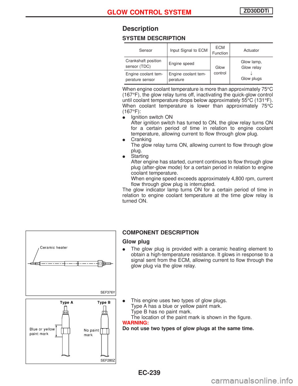
IThe glow plug is provided with a ceramic heating element to
obtain a high-temperature resistance. It glows in response to a
signal sent from the ECM, allowing current to flow through the
glow plug via the glow relay.
IThis engine uses two types of glow plugs.
Type A has a blue or yellow paint mark.
Type B has no paint mark.
The location of the paint mark is shown in the figure.
WARNING:
Do not use two types of glow plugs at the same time.
SEF376Y
SEF280Z
GLOW CONTROL SYSTEMZD30DDTi
EC-239
Page 604 of 1767
Diagnostic Procedure
1 INSPECTION START
Check fuel level, fuel supplying system, starter motor, etc.
OK or NG
OKEGO TO 2.
NGECorrect.
2 CHECK INSTALLATION
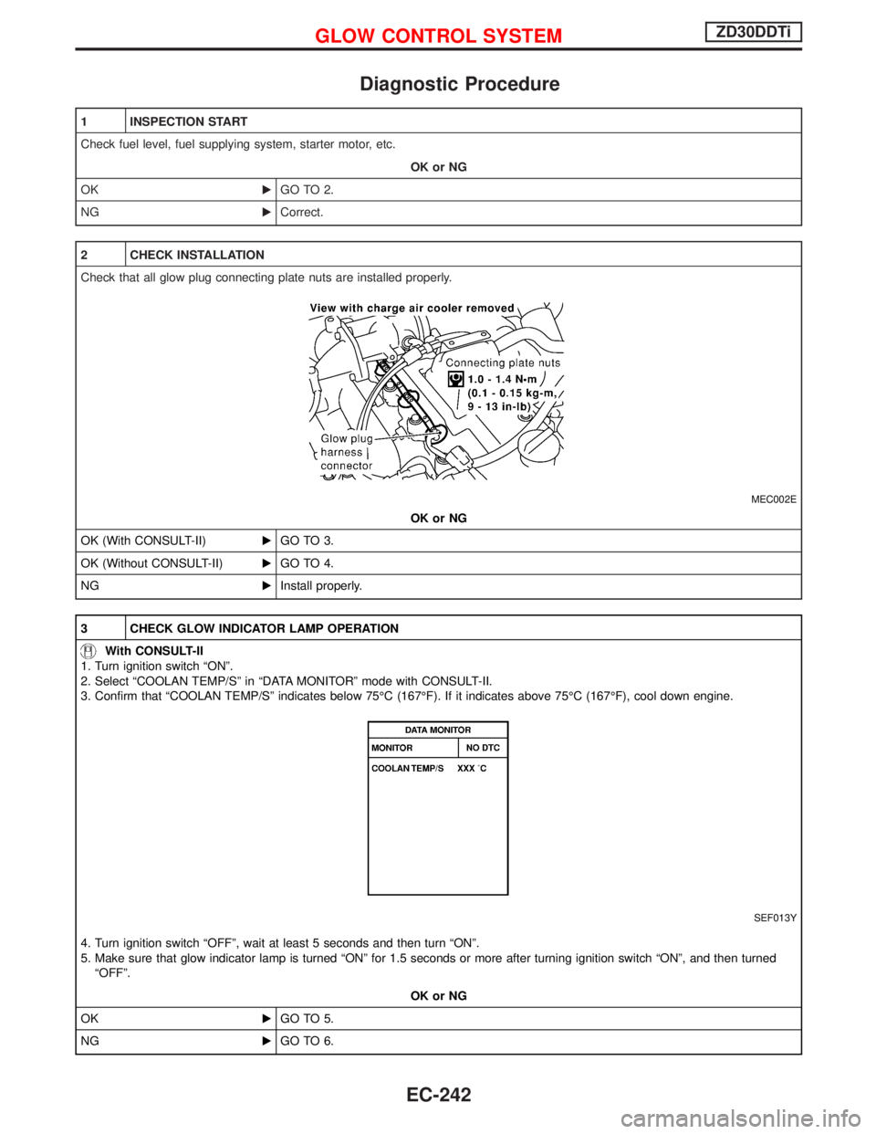
Check that all glow plug connecting plate nuts are installed properly.
MEC002E
OK or NG
OK (With CONSULT-II)EGO TO 3.
OK (Without CONSULT-II)EGO TO 4.
NGEInstall properly.
3 CHECK GLOW INDICATOR LAMP OPERATION
With CONSULT-II
1. Turn ignition switch ªONº.
2. Select ªCOOLAN TEMP/Sº in ªDATA MONITORº mode with CONSULT-II.
3. Confirm that ªCOOLAN TEMP/Sº indicates below 75ÉC (167ÉF). If it indicates above 75ÉC (167ÉF), cool down engine.
SEF013Y
4. Turn ignition switch ªOFFº, wait at least 5 seconds and then turn ªONº.
5. Make sure that glow indicator lamp is turned ªONº for 1.5 seconds or more after turning ignition switch ªONº, and then turned
ªOFFº.
OK or NG
OKEGO TO 5.
NGEGO TO 6.
GLOW CONTROL SYSTEMZD30DDTi
EC-242
Page 605 of 1767
4 CHECK GLOW INDICATOR LAMP OPERATION
Without CONSULT-II
1. Turn ignition switch ªONº.
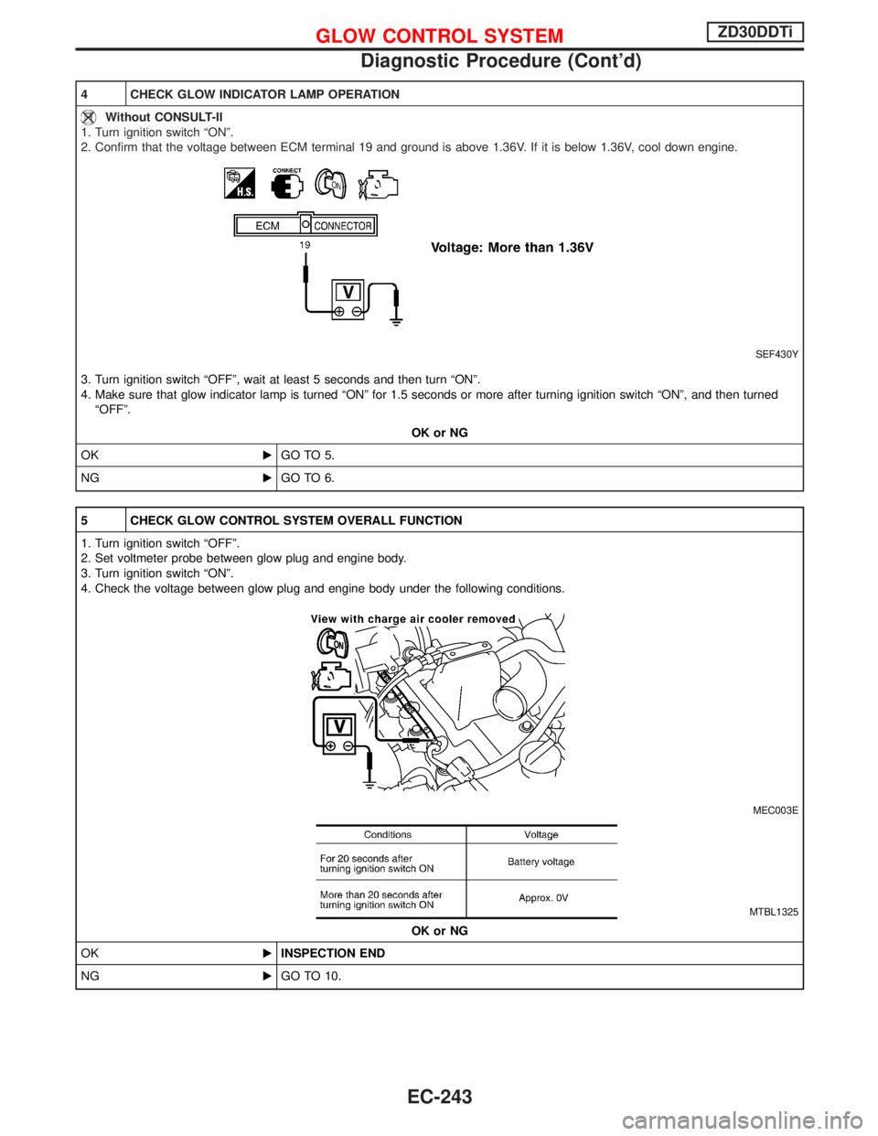
2. Confirm that the voltage between ECM terminal 19 and ground is above 1.36V. If it is below 1.36V, cool down engine.
SEF430Y
3. Turn ignition switch ªOFFº, wait at least 5 seconds and then turn ªONº.
4. Make sure that glow indicator lamp is turned ªONº for 1.5 seconds or more after turning ignition switch ªONº, and then turned
ªOFFº.
OK or NG
OKEGO TO 5.
NGEGO TO 6.
5 CHECK GLOW CONTROL SYSTEM OVERALL FUNCTION
1. Turn ignition switch ªOFFº.
2. Set voltmeter probe between glow plug and engine body.
3. Turn ignition switch ªONº.
4. Check the voltage between glow plug and engine body under the following conditions.
MEC003E
MTBL1325
OK or NG
OKEINSPECTION END
NGEGO TO 10.
GLOW CONTROL SYSTEMZD30DDTi
Diagnostic Procedure (Cont'd)
EC-243
Page 608 of 1767
13 DETECT MALFUNCTIONING PART
Check the following.
IHarness connectors M787, F66 (LHD models)
IHarness for open or short between glow relay and ECM
ERepair open circuit or short to ground or short to power in harness or connectors.
14 CHECK HARNESS CONTINUITY BETWEEN GLOW RELAY AND GLOW PLUG FOR OPEN AND SHORT
1. Disconnect glow plug harness connector.
2. Check harness continuity between glow relay terminal 3 and glow plug harness connector. Refer to Wiring Diagram.
Continuity should exist.
3. Also check harness for short to ground and short to power.
OK or NG
OKEGO TO 16.
NGEGO TO 15.
15 DETECT MALFUNCTIONING PART
Check the following.
IHarness connectors M45, E202
IHarness connectors E230, E241
IHarness for open or short between glow relay and glow plug
ERepair open circuit or short to ground or short to power in harness or connectors.
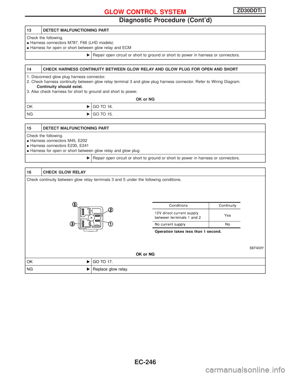
16 CHECK GLOW RELAY
Check continuity between glow relay terminals 3 and 5 under the following conditions.
SEF433Y
OK or NG
OKEGO TO 17.
NGEReplace glow relay.
GLOW CONTROL SYSTEMZD30DDTi
Diagnostic Procedure (Cont'd)
EC-246
Page 609 of 1767
![NISSAN TERRANO 2002 Service Repair Manual 17 CHECK GLOW PLUG
1. Remove glow plug connecting plate.
2. Check glow plug resistance.
MEC005EResistance: Approx. 0.5W[at 20ÉC (68ÉF)]
NOTE:
IDo not bump glow plug heating element. If it is bumped,](/img/5/57393/w960_57393-608.png "NISSAN TERRANO 2002 Service Repair Manual 17 CHECK GLOW PLUG
1. Remove glow plug connecting plate.
2. Check glow plug resistance.
MEC005EResistance: Approx. 0.5W[at 20ÉC (68ÉF)]
NOTE:
IDo not bump glow plug heating element. If it is bumped,")
17 CHECK GLOW PLUG
1. Remove glow plug connecting plate.
2. Check glow plug resistance.
MEC005EResistance: Approx. 0.5W[at 20ÉC (68ÉF)]
NOTE:
IDo not bump glow plug heating element. If it is bumped, replace glow plug with a new one.
IIf glow plug is dropped from a height of 10 cm (3.94 in) or higher, replace with a new one.
IIf glow plug installation hole is contaminated with carbon, remove it with a reamer or suitable tool.
IHand-tighten glow plug by turning it two or three times, then tighten using a tool to specified torque.
:15-20N×m (1.5 - 2.1 kg-m, 11 - 15 ft-lb)
OK or NG
OKEGO TO 18.
NGEReplace glow plug.
18 CHECK INTERMITTENT INCIDENT
Refer to ªTROUBLE DIAGNOSIS FOR INTERMITTENT INCIDENTº, EC-78.
EINSPECTION END
GLOW CONTROL SYSTEMZD30DDTi
Diagnostic Procedure (Cont'd)
EC-247
Page 654 of 1767
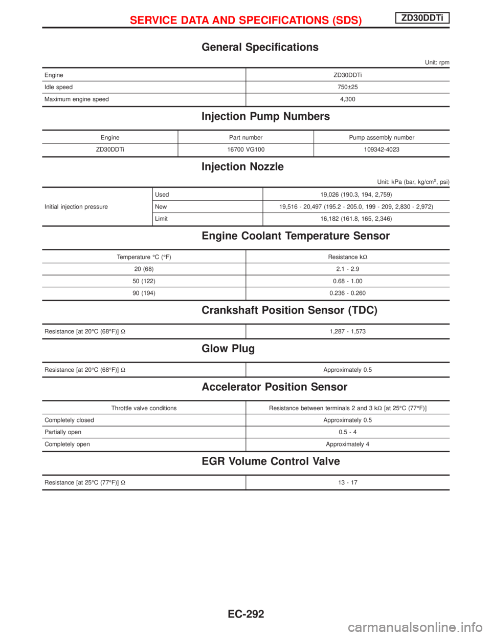
General Specifications
Unit: rpm
EngineZD30DDTi
Idle speed750 25
Maximum engine speed4,300
Injection Pump Numbers
Engine Part number Pump assembly number
ZD30DDTi 16700 VG100 109342-4023
Injection Nozzle
Unit: kPa (bar, kg/cm2, psi)
Initial injection pressureUsed 19,026 (190.3, 194, 2,759)
New 19,516 - 20,497 (195.2 - 205.0, 199 - 209, 2,830 - 2,972)
Limit 16,182 (161.8, 165, 2,346)
Engine Coolant Temperature Sensor
Temperature ÉC (ÉF) Resistance kW
20 (68) 2.1 - 2.9
50 (122) 0.68 - 1.00
90 (194) 0.236 - 0.260
Crankshaft Position Sensor (TDC)
Resistance [at 20ÉC (68ÉF)]W1,287 - 1,573
Glow Plug
Resistance [at 20ÉC (68ÉF)]WApproximately 0.5
Accelerator Position Sensor
Throttle valve conditions Resistance between terminals 2 and 3 kW[at 25ÉC (77ÉF)]
Completely closedApproximately 0.5
Partially open0.5-4
Completely openApproximately 4
EGR Volume Control Valve
Resistance [at 25ÉC (77ÉF)]W13-17
SERVICE DATA AND SPECIFICATIONS (SDS)ZD30DDTi
EC-292
Page 673 of 1767
Air Conditioning Cut Control
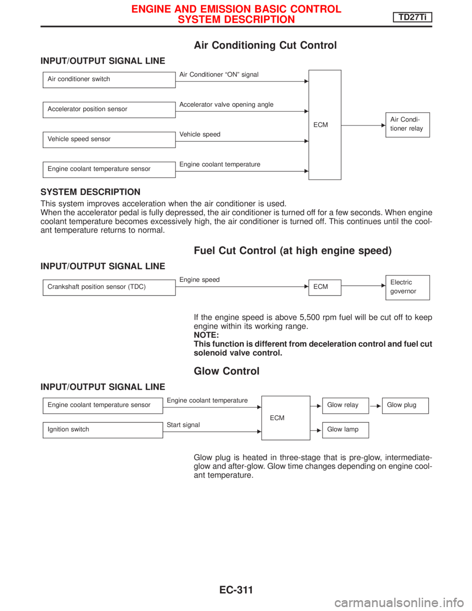
INPUT/OUTPUT SIGNAL LINE
Air conditioner switchEAir Conditioner ªONº signal
ECM
EAir Condi-
tioner relay
Accelerator position sensorEAccelerator valve opening angle
Vehicle speed sensor
EVehicle speed
Engine coolant temperature sensor
EEngine coolant temperature
SYSTEM DESCRIPTION
This system improves acceleration when the air conditioner is used.
When the accelerator pedal is fully depressed, the air conditioner is turned off for a few seconds. When engine
coolant temperature becomes excessively high, the air conditioner is turned off. This continues until the cool-
ant temperature returns to normal.
Fuel Cut Control (at high engine speed)
INPUT/OUTPUT SIGNAL LINE
Crankshaft position sensor (TDC)EEngine speed
ECMEElectric
governor
If the engine speed is above 5,500 rpm fuel will be cut off to keep
engine within its working range.
NOTE:
This function is different from deceleration control and fuel cut
solenoid valve control.
Glow Control
INPUT/OUTPUT SIGNAL LINE
Engine coolant temperature sensorEEngine coolant temperature
ECMEGlow relayEGlow plug
Ignition switchEStart signalEGlow lamp
Glow plug is heated in three-stage that is pre-glow, intermediate-
glow and after-glow. Glow time changes depending on engine cool-
ant temperature.
ENGINE AND EMISSION BASIC CONTROL
SYSTEM DESCRIPTIONTD27Ti
EC-311
Page 751 of 1767
System Description
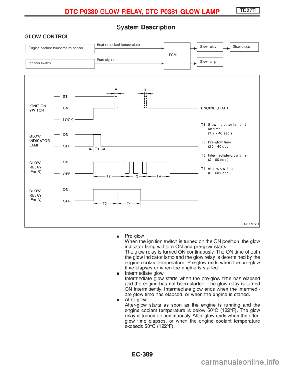
GLOW CONTROL
Engine coolant temperature sensorEEngine coolant temperature
ECMEGlow relayEGlow plugs
Ignition switchEStart signalEGlow lamp
IPre-glow
When the ignition switch is turned on the ON position, the glow
indicator lamp will turn ON and pre-glow starts.
The glow relay is turned ON continuously. The ON time of both
the glow indicator lamp and the glow relay is determined by the
engine coolant temperature. Pre-glow ends when the pre-glow
time elapses or when the engine is started.
IIntermediate glow
Intermediate glow starts when the pre-glow time has elapsed
and the engine has not been started. The glow relay is turned
ON intermittently. Intermediate glow ends when the intermedi-
ate glow time has elapsed, or when the engine is started.
IAfter-glow
After-glow starts as soon as the engine is running and the
engine coolant temperature is below 50ÉC (122ÉF). The glow
relay is turned on continuously. After-glow ends when the after-
glow time elapses, or when the engine coolant temperature
exceeds 50ÉC (122ÉF).
MEC972D
DTC P0380 GLOW RELAY, DTC P0381 GLOW LAMPTD27Ti
EC-389
Page 752 of 1767
Component Description
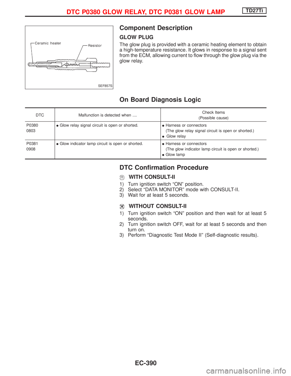
GLOW PLUG
The glow plug is provided with a ceramic heating element to obtain
a high-temperature resistance. It glows in response to a signal sent
from the ECM, allowing current to flow through the glow plug via the
glow relay.
On Board Diagnosis Logic
DTC Malfunction is detected when ....Check Items
(Possible cause)
P0380
0803IGlow relay signal circuit is open or shorted.IHarness or connectors
(The glow relay signal circuit is open or shorted.)
IGlow relay
P0381
0908IGlow indicator lamp circuit is open or shorted.IHarness or connectors
(The glow indicator lamp circuit is open or shorted.)
IGlow lamp
DTC Confirmation Procedure
WITH CONSULT-II
1) Turn ignition switch ªONº position.
2) Select ªDATA MONITORº mode with CONSULT-II.
3) Wait for at least 5 seconds.
WITHOUT CONSULT-II
1) Turn ignition switch ªONº position and then wait for at least 5
seconds.
2) Turn ignition switch OFF, wait for at least 5 seconds and then
turn on.
3) Perform ªDiagnostic Test Mode IIº (Self-diagnostic results).
SEF857S
DTC P0380 GLOW RELAY, DTC P0381 GLOW LAMPTD27Ti
EC-390