height adjustment NISSAN TERRANO 2002 Service Repair Manual
[x] Cancel search | Manufacturer: NISSAN, Model Year: 2002, Model line: TERRANO, Model: NISSAN TERRANO 2002Pages: 1767, PDF Size: 41.51 MB
Page 217 of 1767
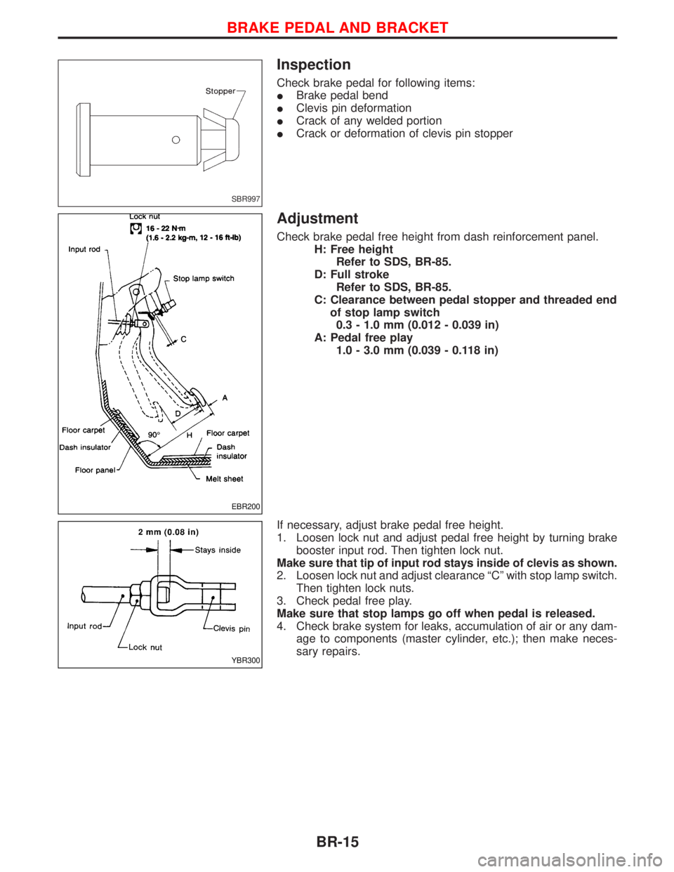
Inspection
Check brake pedal for following items:
IBrake pedal bend
IClevis pin deformation
ICrack of any welded portion
ICrack or deformation of clevis pin stopper
Adjustment
Check brake pedal free height from dash reinforcement panel.
H: Free height
Refer to SDS, BR-85.
D: Full stroke
Refer to SDS, BR-85.
C: Clearance between pedal stopper and threaded end
of stop lamp switch
0.3 - 1.0 mm (0.012 - 0.039 in)
A: Pedal free play
1.0 - 3.0 mm (0.039 - 0.118 in)
If necessary, adjust brake pedal free height.
1. Loosen lock nut and adjust pedal free height by turning brake
booster input rod. Then tighten lock nut.
Make sure that tip of input rod stays inside of clevis as shown.
2. Loosen lock nut and adjust clearance ªCº with stop lamp switch.
Then tighten lock nuts.
3. Check pedal free play.
Make sure that stop lamps go off when pedal is released.
4. Check brake system for leaks, accumulation of air or any dam-
age to components (master cylinder, etc.); then make neces-
sary repairs.
SBR997
EBR200
YBR300
BRAKE PEDAL AND BRACKET
BR-15
Page 287 of 1767
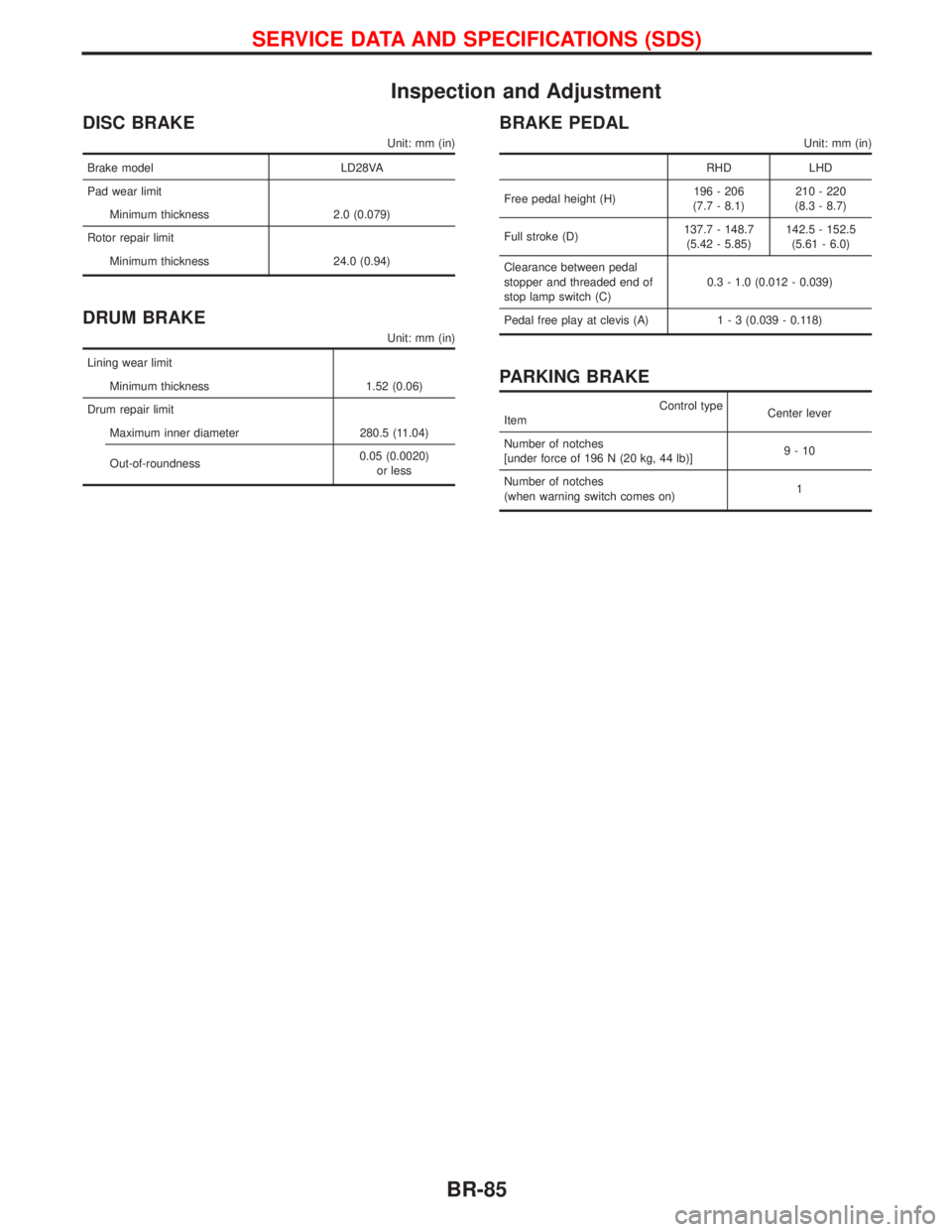
Inspection and Adjustment
DISC BRAKE
Unit: mm (in)
Brake model LD28VA
Pad wear limit
Minimum thickness 2.0 (0.079)
Rotor repair limit
Minimum thickness 24.0 (0.94)
DRUM BRAKE
Unit: mm (in)
Lining wear limit
Minimum thickness 1.52 (0.06)
Drum repair limit
Maximum inner diameter 280.5 (11.04)
Out-of-roundness0.05 (0.0020)
or less
BRAKE PEDAL
Unit: mm (in)
RHD LHD
Free pedal height (H)196 - 206
(7.7 - 8.1)210 - 220
(8.3 - 8.7)
Full stroke (D)137.7 - 148.7
(5.42 - 5.85)142.5 - 152.5
(5.61 - 6.0)
Clearance between pedal
stopper and threaded end of
stop lamp switch (C)0.3 - 1.0 (0.012 - 0.039)
Pedal free play at clevis (A)1 - 3 (0.039 - 0.118)
PARKING BRAKE
Control type
ItemCenter lever
Number of notches
[under force of 196 N (20 kg, 44 lb)]9-10
Number of notches
(when warning switch comes on)1
SERVICE DATA AND SPECIFICATIONS (SDS)
BR-85
Page 353 of 1767
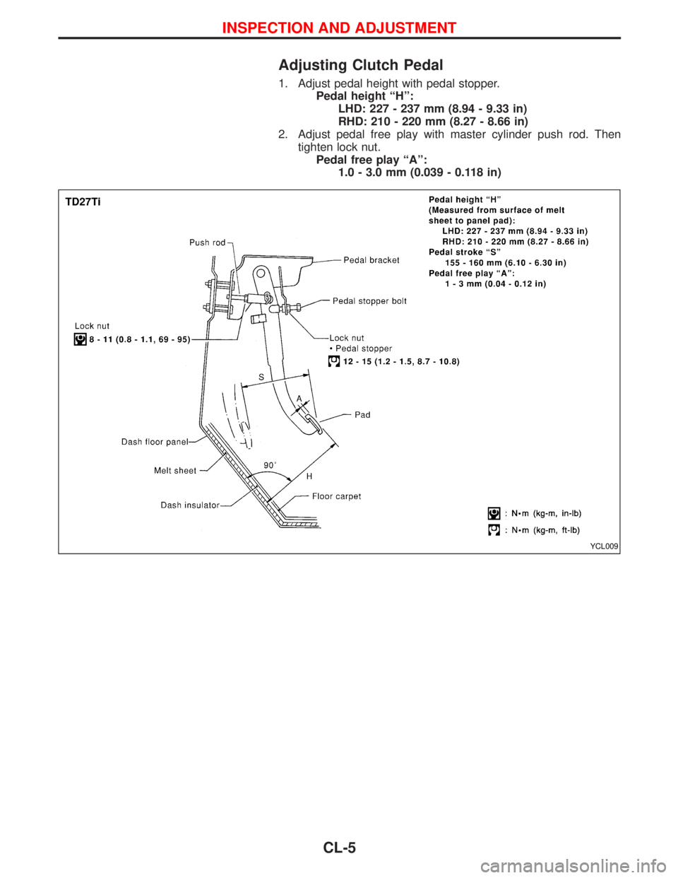
Adjusting Clutch Pedal
1. Adjust pedal height with pedal stopper.
Pedal height ªHº:
LHD: 227 - 237 mm (8.94 - 9.33 in)
RHD: 210 - 220 mm (8.27 - 8.66 in)
2. Adjust pedal free play with master cylinder push rod. Then
tighten lock nut.
Pedal free play ªAº:
1.0 - 3.0 mm (0.039 - 0.118 in)
YCL009
INSPECTION AND ADJUSTMENT
CL-5
Page 360 of 1767
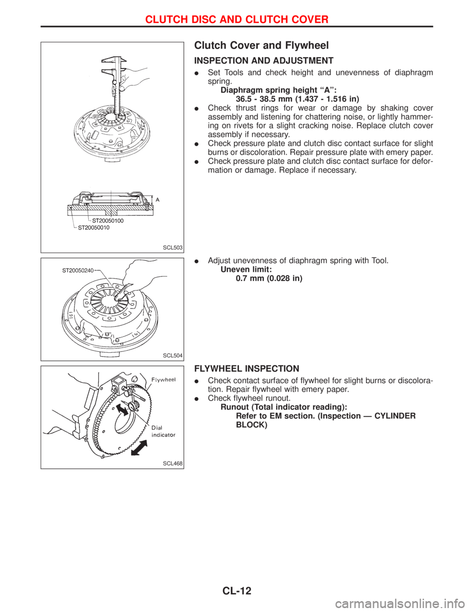
Clutch Cover and Flywheel
INSPECTION AND ADJUSTMENT
ISet Tools and check height and unevenness of diaphragm
spring.
Diaphragm spring height ªAº:
36.5 - 38.5 mm (1.437 - 1.516 in)
ICheck thrust rings for wear or damage by shaking cover
assembly and listening for chattering noise, or lightly hammer-
ing on rivets for a slight cracking noise. Replace clutch cover
assembly if necessary.
ICheck pressure plate and clutch disc contact surface for slight
burns or discoloration. Repair pressure plate with emery paper.
ICheck pressure plate and clutch disc contact surface for defor-
mation or damage. Replace if necessary.
IAdjust unevenness of diaphragm spring with Tool.
Uneven limit:
0.7 mm (0.028 in)
FLYWHEEL INSPECTION
ICheck contact surface of flywheel for slight burns or discolora-
tion. Repair flywheel with emery paper.
ICheck flywheel runout.
Runout (Total indicator reading):
Refer to EM section. (Inspection Ð CYLINDER
BLOCK)
SCL503
SCL504
SCL468
CLUTCH DISC AND CLUTCH COVER
CL-12
Page 362 of 1767
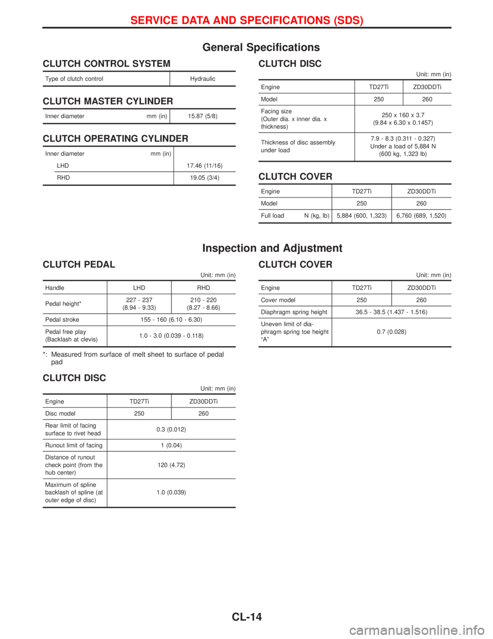
General Specifications
CLUTCH CONTROL SYSTEM
Type of clutch control Hydraulic
CLUTCH MASTER CYLINDER
Inner diameter mm (in) 15.87 (5/8)
CLUTCH OPERATING CYLINDER
Inner diameter mm (in)
LHD 17.46 (11/16)
RHD 19.05 (3/4)
CLUTCH DISC
Unit: mm (in)
Engine TD27Ti ZD30DDTi
Model 250 260
Facing size
(Outer dia. x inner dia. x
thickness)250 x 160 x 3.7
(9.84 x 6.30 x 0.1457)
Thickness of disc assembly
under load7.9 - 8.3 (0.311 - 0.327)
Under a load of 5,884 N
(600 kg, 1,323 lb)
CLUTCH COVER
Engine TD27Ti ZD30DDTi
Model 250 260
Full load N (kg, lb) 5,884 (600, 1,323) 6,760 (689, 1,520)
Inspection and Adjustment
CLUTCH PEDAL
Unit: mm (in)
Handle LHD RHD
Pedal height*227 - 237
(8.94 - 9.33)210 - 220
(8.27 - 8.66)
Pedal stroke 155 - 160 (6.10 - 6.30)
Pedal free play
(Backlash at clevis)1.0 - 3.0 (0.039 - 0.118)
*: Measured from surface of melt sheet to surface of pedal
pad
CLUTCH DISC
Unit: mm (in)
Engine TD27Ti ZD30DDTi
Disc model 250 260
Rear limit of facing
surface to rivet head0.3 (0.012)
Runout limit of facing 1 (0.04)
Distance of runout
check point (from the
hub center)120 (4.72)
Maximum of spline
backlash of spline (at
outer edge of disc)1.0 (0.039)
CLUTCH COVER
Unit: mm (in)
Engine TD27Ti ZD30DDTi
Cover model 250 260
Diaphragm spring height 36.5 - 38.5 (1.437 - 1.516)
Uneven limit of dia-
phragm spring toe height
ªAº0.7 (0.028)
SERVICE DATA AND SPECIFICATIONS (SDS)
CL-14
Page 1252 of 1767
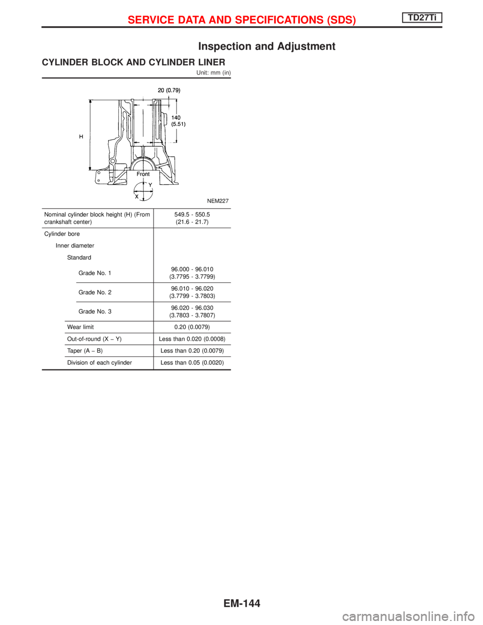
Inspection and Adjustment
CYLINDER BLOCK AND CYLINDER LINER
Unit: mm (in)
NEM227
Nominal cylinder block height (H) (From
crankshaft center)549.5 - 550.5
(21.6 - 21.7)
Cylinder bore
Inner diameter
Standard
Grade No. 196.000 - 96.010
(3.7795 - 3.7799)
Grade No. 296.010 - 96.020
(3.7799 - 3.7803)
Grade No. 396.020 - 96.030
(3.7803 - 3.7807)
Wear limit 0.20 (0.0079)
Out-of-round (X þ Y) Less than 0.020 (0.0008)
Taper (A þ B) Less than 0.20 (0.0079)
Division of each cylinder Less than 0.05 (0.0020)
SERVICE DATA AND SPECIFICATIONS (SDS)TD27Ti
EM-144
Page 1254 of 1767
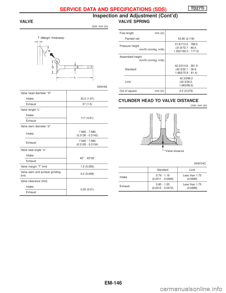
VA LV E
Unit: mm (in)
SEM188
Valve head diameter ªDº
Intake 42.5 (1.67)
Exhaust 37 (1.5)
Valve length ªLº
Intake
117 (4.61)
Exhaust
Valve stem diameter ªdº
Intake7.965 - 7.980
(0.3136 - 0.3142)
Exhaust7.945 - 7.960
(0.3128 - 0.3134)
Valve seat angle ªaº
Intake
45É - 45É30¢
Exhaust
Valve margin ªTº limit 1.5 (0.059)
Valve stem end surface grinding
limit0.2 (0.008)
Valve clearance (Hot)
Intake
0.25 (0.01)
Exhaust
VALVE SPRING
Free length mm (in)
Painted red 53.80 (2.118)
Pressure height
mm/N (mm/kg, in/lb)31.8/713.0 - 788.5
(31.8/72.7 - 80.4,
1.252/160.3 - 177.3)
Assembled height
mm/N (mm/kg, in/lb)
Standard42.3/314.8 - 361.9
(42.3/32.1 - 36.9,
1.665/70.8 - 81.4)
Limit42.3/296.2
(42.3/30.2,
1.665/66.6)
Out of square mm (in) 2.0 (0.079)
CYLINDER HEAD TO VALVE DISTANCE
Unit: mm (in)
SEM724C
Standard Limit
Intake0.79 - 1.19
(0.0311 - 0.0469)Less than 1.75
(0.0689)
Exhaust0.80 - 1.20
(0.0315 - 0.0472)Less than 1.75
(0.0689)
SERVICE DATA AND SPECIFICATIONS (SDS)TD27Ti
Inspection and Adjustment (Cont'd)
EM-146
Page 1255 of 1767
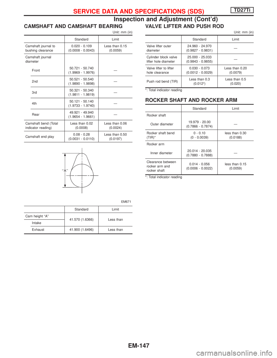
CAMSHAFT AND CAMSHAFT BEARING
Unit: mm (in)
Standard Limit
Camshaft journal to
bushing clearance0.020 - 0.109
(0.0008 - 0.0043)Less than 0.15
(0.0059)
Camshaft journal
diameter
Front50.721 - 50.740
(1.9969 - 1.9976)Ð
2nd50.521 - 50.540
(1.9890 - 1.9898)Ð
3rd50.321 - 50.340
(1.9811 - 1.9819)Ð
4th50.121 - 50.140
(1.9733 - 1.9740)Ð
Rear49.921 - 49.940
(1.9654 - 1.9661)Ð
Camshaft bend (Total
indicator reading)Less than 0.02
(0.0008)Less than 0.06
(0.0024)
Camshaft end play0.08 - 0.28
(0.0031 - 0.0110)Less than 0.50
(0.0197)
EM671
Standard Limit
Cam height ªAº
41.570 (1.6366) Less than
Intake
Exhaust 41.900 (1.6496) Less than
VALVE LIFTER AND PUSH ROD
Unit: mm (in)
Standard Limit
Valve lifter outer
diameter24.960 - 24.970
(0.9827 - 0.9831)Ð
Cylinder block valve
lifter hole diameter25.000 - 25.033
(0.9843 - 0.9855)Ð
Valve lifter to lifter
hole clearance0.030 - 0.073
(0.0012 - 0.0029)Less than 0.20
(0.0079)
Push rod bend (TIR)Less than 0.3
(0.012É)Less than 0.5
(0.020)
*: Total indicator reading
ROCKER SHAFT AND ROCKER ARM
Standard Limit
Rocker shaft
Outer diameter19.979 - 20.00
(0.7866 - 0.7874)Ð
Rocker shaft bend
(TIR)*0 - 0.10
(0 - 0.0039)less than 0.30
(0.0188)
Rocker arm
Inner diameter20.014 - 20.035
(0.7880 - 0.7888)Ð
Clearance between
rocker arm and
rocker shaft0.014 - 0.056
(0.0006 - 0.0022)less than 0.15
(0.0059)
*: Total indicator reading
SERVICE DATA AND SPECIFICATIONS (SDS)TD27Ti
Inspection and Adjustment (Cont'd)
EM-147
Page 1258 of 1767
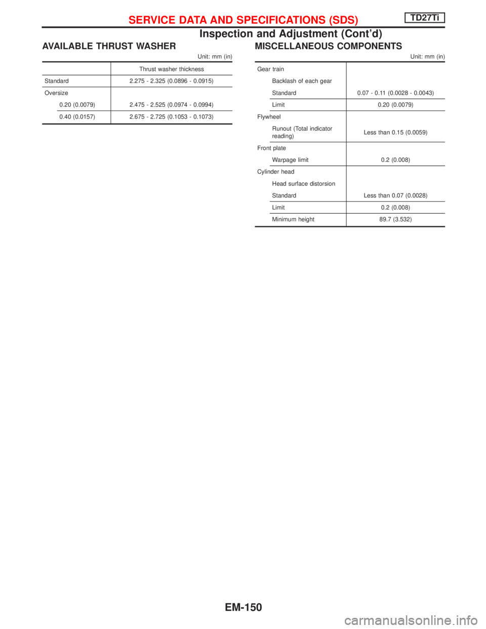
AVAILABLE THRUST WASHER
Unit: mm (in)
Thrust washer thickness
Standard 2.275 - 2.325 (0.0896 - 0.0915)
Oversize
0.20 (0.0079) 2.475 - 2.525 (0.0974 - 0.0994)
0.40 (0.0157) 2.675 - 2.725 (0.1053 - 0.1073)
MISCELLANEOUS COMPONENTS
Unit: mm (in)
Gear train
Backlash of each gear
Standard 0.07 - 0.11 (0.0028 - 0.0043)
Limit 0.20 (0.0079)
Flywheel
Runout (Total indicator
reading)Less than 0.15 (0.0059)
Front plate
Warpage limit 0.2 (0.008)
Cylinder head
Head surface distorsion
Standard Less than 0.07 (0.0028)
Limit 0.2 (0.008)
Minimum height 89.7 (3.532)
SERVICE DATA AND SPECIFICATIONS (SDS)TD27Ti
Inspection and Adjustment (Cont'd)
EM-150
Page 1266 of 1767
Front Wheel Alignment
Before checking front wheel alignment, be sure to make a prelimi-
nary inspection.
PRELIMINARY INSPECTION
1. Check the tires for wear and proper inflation.
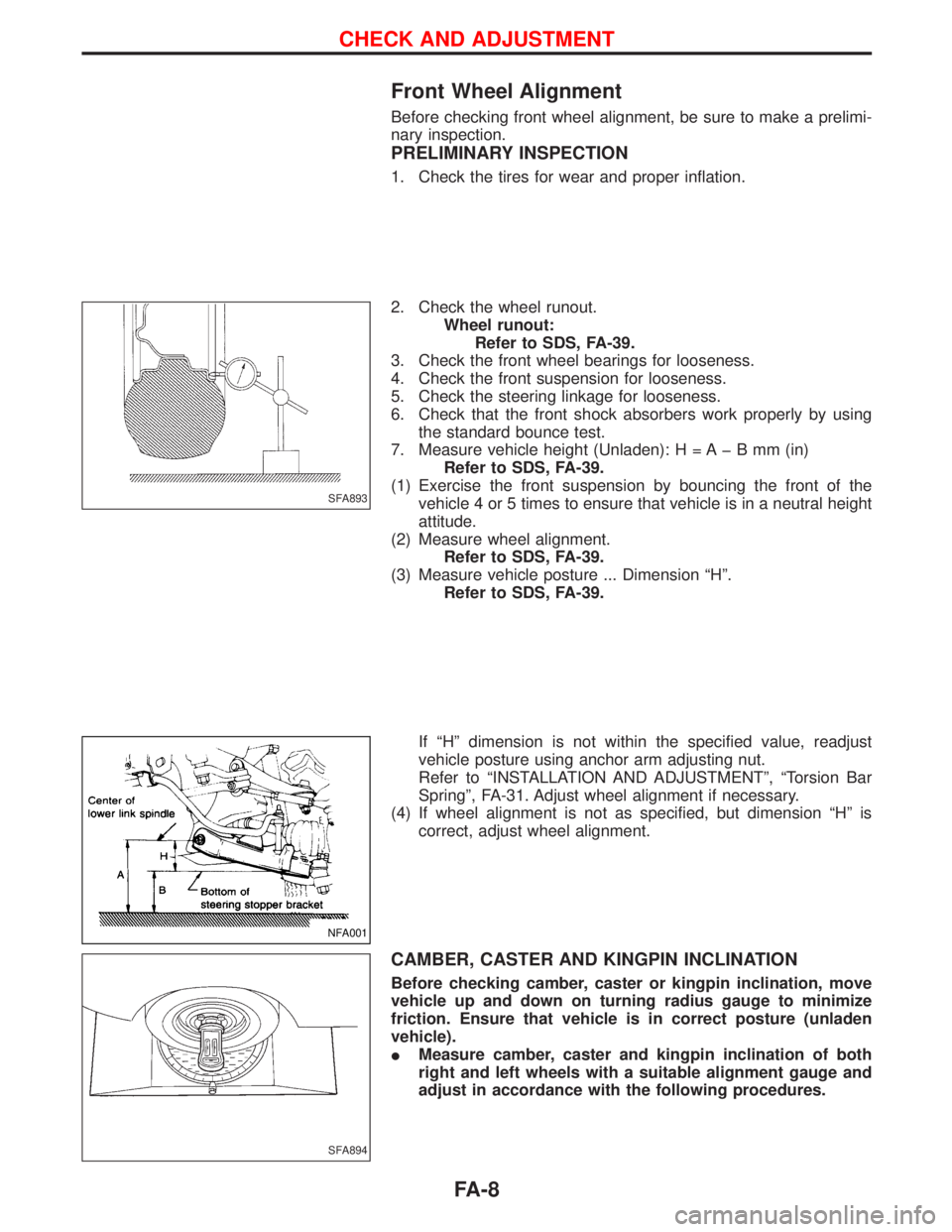
2. Check the wheel runout.
Wheel runout:
Refer to SDS, FA-39.
3. Check the front wheel bearings for looseness.
4. Check the front suspension for looseness.
5. Check the steering linkage for looseness.
6. Check that the front shock absorbers work properly by using
the standard bounce test.
7. Measure vehicle height (Unladen): H = A þ B mm (in)
Refer to SDS, FA-39.
(1) Exercise the front suspension by bouncing the front of the
vehicle 4 or 5 times to ensure that vehicle is in a neutral height
attitude.
(2) Measure wheel alignment.
Refer to SDS, FA-39.
(3) Measure vehicle posture ... Dimension ªHº.
Refer to SDS, FA-39.
If ªHº dimension is not within the specified value, readjust
vehicle posture using anchor arm adjusting nut.
Refer to ªINSTALLATION AND ADJUSTMENTº, ªTorsion Bar
Springº, FA-31. Adjust wheel alignment if necessary.
(4) If wheel alignment is not as specified, but dimension ªHº is
correct, adjust wheel alignment.
CAMBER, CASTER AND KINGPIN INCLINATION
Before checking camber, caster or kingpin inclination, move
vehicle up and down on turning radius gauge to minimize
friction. Ensure that vehicle is in correct posture (unladen
vehicle).
IMeasure camber, caster and kingpin inclination of both
right and left wheels with a suitable alignment gauge and
adjust in accordance with the following procedures.
SFA893
NFA001
SFA894
CHECK AND ADJUSTMENT
FA-8