overheating NISSAN TERRANO 2002 Service Repair Manual
[x] Cancel search | Manufacturer: NISSAN, Model Year: 2002, Model line: TERRANO, Model: NISSAN TERRANO 2002Pages: 1767, PDF Size: 41.51 MB
Page 364 of 1767
DTC Confirmation Procedure ..................................105
Wiring Diagram ........................................................106
Diagnostic Procedure ..............................................107
DTC 0208 OVER HEAT...............................................109
Description ...............................................................109
CONSULT-II Reference Value in Data Monitor
Mode ........................................................................109
ECM Terminals and Reference Value ..................... 110
On Board Diagnosis Logic....................................... 110
Overall Function Check ........................................... 111
Wiring Diagram ........................................................ 112
Diagnostic Procedure .............................................. 114
Main 12 Causes of Overheating..............................120
DTC 0301 ECM 2, DTC 0901 ECM 12.......................121
Description ...............................................................121
On Board Diagnosis Logic.......................................121
DTC Confirmation Procedure ..................................121
Diagnostic Procedure ..............................................122
DTC 0402 P9×FUEL TEMP SEN.................................123
Description ...............................................................123
CONSULT-II Reference Value in Data Monitor
Mode ........................................................................124
ECM Terminals and Reference Value .....................124
On Board Diagnosis Logic.......................................124
DTC Confirmation Procedure ..................................125
Wiring Diagram ........................................................126
Diagnostic Procedure ..............................................128
DTC 0403 ACCEL POS SENSOR..............................130
Description ...............................................................130
CONSULT-II Reference Value in Data Monitor
Mode ........................................................................130
ECM Terminals and Reference Value .....................131
On Board Diagnosis Logic.......................................131
DTC Confirmation Procedure ..................................132
Wiring Diagram ........................................................133
Diagnostic Procedure ..............................................135
DTC 0406 INT AIR VOL..............................................143
On Board Diagnosis Logic.......................................143
DTC Confirmation Procedure ..................................143
Diagnostic Procedure ..............................................144
DTC 0407 CRANK POS SEN (TDC)..........................145
Description ...............................................................145
CONSULT-II Reference Value in Data Monitor
Mode ........................................................................145
ECM Terminals and Reference Value .....................145
On Board Diagnosis Logic.......................................146
DTC Confirmation Procedure ..................................146
Wiring Diagram ........................................................147
Diagnostic Procedure ..............................................149
DTC 0502 BATTERY VOLTAGE.................................153
On Board Diagnosis Logic.......................................153
DTC Confirmation Procedure ..................................153Diagnostic Procedure ..............................................153
DTC 0504 A/T COMM LINE........................................155
System Description ..................................................155
ECM Terminals and Reference Value .....................155
On Board Diagnosis Logic.......................................155
DTC Confirmation Procedure ..................................156
Overall Function Check ...........................................156
Wiring Diagram ........................................................157
Diagnostic Procedure ..............................................159
DTC 0701 P1×CAM POS SEN.....................................161
Description ...............................................................161
CONSULT-II Reference Value in Data Monitor
Mode ........................................................................162
ECM Terminals and Reference Value .....................162
On Board Diagnosis Logic.......................................162
DTC Confirmation Procedure ..................................163
Wiring Diagram ........................................................164
Diagnostic Procedure ..............................................166
DTC 0702 P2×TDC PULSE SIG..................................168
Description ...............................................................168
CONSULT-II Reference Value in Data Monitor
Mode ........................................................................169
ECM Terminals and Reference Value .....................169
On Board Diagnosis Logic.......................................169
DTC Confirmation Procedure ..................................170
Wiring Diagram ........................................................171
Diagnostic Procedure ..............................................173
DTC 0703 P3×PUMP COMM LINE..............................175
Description ...............................................................175
CONSULT-II Reference Value in Data Monitor
Mode ........................................................................176
ECM Terminals and Reference Value .....................176
On Board Diagnosis Logic.......................................176
DTC Confirmation Procedure ..................................177
Wiring Diagram ........................................................178
Diagnostic Procedure ..............................................180
DTC 0704 P4×SPILL/V CIRC, DTC 0706 P6×SPILL
VA LV E..........................................................................182
Description ...............................................................182
CONSULT-II Reference Value in Data Monitor
Mode ........................................................................183
ECM Terminals and Reference Value .....................183
On Board Diagnosis Logic.......................................183
DTC Confirmation Procedure ..................................184
Wiring Diagram ........................................................185
Diagnostic Procedure ..............................................187
DTC 0705 P5×PUMP C/MODULE................................189
Description ...............................................................189
CONSULT-II Reference Value in Data Monitor
Mode ........................................................................190
ECM Terminals and Reference Value .....................190
On Board Diagnosis Logic.......................................190
CONTENTS(Cont'd)
EC-2
Page 367 of 1767
Wiring Diagram ........................................................373
Diagnostic Procedure ..............................................374
Component Inspection .............................................375
DTC P0215 FUEL CUT S/V 1.....................................376
Component Description ...........................................376
On Board Diagnosis Logic.......................................376
DTC Confirmation Procedure ..................................376
Wiring Diagram ........................................................377
Diagnostic Procedure ..............................................378
Component Inspection .............................................379
DTC P0216 INJ TIMING CONT/V, DTC P1246 F/
INJ TIMG F/B...............................................................380
Component Description ...........................................380
On Board Diagnosis Logic.......................................380
DTC P0216 Confirmation Procedure.......................380
DTC P1246 Confirmation Procedure.......................381
Wiring Diagram ........................................................382
Diagnostic Procedure ..............................................383
Component Inspection .............................................384
DTC P0335 CRANK POS SEN (TDC)........................385
Component Description ...........................................385
On Board Diagnosis Logic.......................................385
DTC Confirmation Procedure ..................................385
Wiring Diagram ........................................................386
Diagnostic Procedure ..............................................387
Component Inspection .............................................388
DTC P0380 GLOW RELAY, DTC P0381 GLOW
LAMP...........................................................................389
System Description ..................................................389
Component Description ...........................................390
On Board Diagnosis Logic.......................................390
DTC Confirmation Procedure ..................................390
Wiring Diagram ........................................................391
Diagnostic Procedure ..............................................393
System Operation Check.........................................395
Component Inspection .............................................396
DTC P0500 VEHICLE SPEED SEN............................397
Component Description ...........................................397
On Board Diagnosis Logic.......................................397
Overall Function Check ...........................................397
Wiring Diagram ........................................................398
Diagnostic Procedure ..............................................399
DTC P0571 BRAKE SW..............................................400
Component Description ...........................................400
On Board Diagnosis Logic.......................................400
DTC Confirmation Procedure ..................................400
Wiring Diagram ........................................................401
Diagnostic Procedure ..............................................402
Component Inspection .............................................403
DTC P0650 MI.............................................................404
Component Description ...........................................404
On Board Diagnosis Logic.......................................404DTC Confirmation Procedure ..................................404
Wiring Diagram ........................................................405
Diagnostic Procedure ..............................................406
DTC P1107 ECM 10....................................................407
Description ...............................................................407
On Board Diagnosis Logic.......................................407
DTC Confirmation Procedure ..................................407
Diagnostic Procedure ..............................................408
DTC P1206 F/INJ F/B 2..............................................409
Component Description ...........................................409
On Board Diagnosis Logic.......................................409
DTC Confirmation Procedure ..................................410
Wiring Diagram ........................................................ 411
Diagnostic Procedure ..............................................412
Component Inspection .............................................413
DTC P1207 CONT SLEEV POS SEN.........................414
Component Description ...........................................414
On Board Diagnosis Logic.......................................414
DTC Confirmation Procedure ..................................414
Wiring Diagram ........................................................415
Diagnostic Procedure ..............................................416
Component Inspection .............................................417
DTC P1217 OVER HEAT............................................418
Description ...............................................................418
On Board Diagnosis Logic.......................................418
Overall Function Check ...........................................419
Wiring Diagram ........................................................420
Diagnostic Procedure ..............................................421
Main 12 Causes of Overheating..............................425
Component Inspection .............................................426
DTC P1240 NEEDLE LIFT SEN, DTC P1242
NEEDLE LIFT SE (RPM).............................................427
Component Description ...........................................427
On Board Diagnosis Logic.......................................427
DTC Confirmation Procedure ..................................427
Wiring Diagram ........................................................428
Diagnostic Procedure ..............................................429
Component Inspection .............................................430
DTC P1404 EGR SOL/V A, DTC P1405 EGR SOL/
V B/P1407 (THROTTLE SOLENOID VALVE)............431
System Description ..................................................431
Component Description ...........................................431
On Board Diagnosis Logic.......................................432
DTC Confirmation Procedure ..................................432
Wiring Diagram ........................................................433
Diagnostic Procedure ..............................................436
Component Inspection .............................................439
DTC P1530 AIR CONDITIONER RLY.........................440
Component Description ...........................................440
On Board Diagnosis Logic.......................................440
DTC Confirmation Procedure ..................................440
Wiring Diagram ........................................................441
CONTENTS(Cont'd)
EC-5
Page 472 of 1767
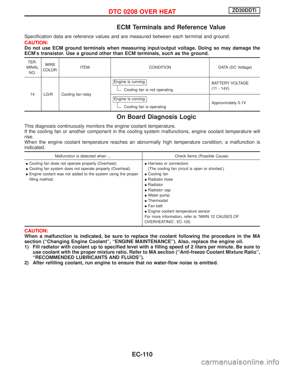
ECM Terminals and Reference Value
Specification data are reference values and are measured between each terminal and ground.
CAUTION:
Do not use ECM ground terminals when measuring input/output voltage. Doing so may damage the
ECM's transistor. Use a ground other than ECM terminals, such as the ground.
TER-
MINAL
NO.WIRE
COLORITEM CONDITION DATA (DC Voltage)
14 LG/R Cooling fan relayEngine is running.
Cooling fan is not operatingBATTERY VOLTAGE
(11 - 14V)
Engine is running.
Cooling fan is operatingApproximately 0.1V
On Board Diagnosis Logic
This diagnosis continuously monitors the engine coolant temperature.
If the cooling fan or another component in the cooling system malfunctions, engine coolant temperature will
rise.
When the engine coolant temperature reaches an abnormally high temperature condition, a malfunction is
indicated.
Malfunction is detected when ... Check Items (Possible Cause)
ICooling fan does not operate properly (Overheat).
ICooling fan system does not operate properly (Overheat).
IEngine coolant was not added to the system using the proper
filling method.IHarness or connectors
(The cooling fan circuit is open or shorted.)
ICooling fan
IRadiator hose
IRadiator
IRadiator cap
IWater pump
IThermostat
IFan belt
IEngine coolant temperature sensor
For more information, refer to ªMAIN 12 CAUSES OF
OVERHEATINGº, EC-120.
CAUTION:
When a malfunction is indicated, be sure to replace the coolant following the procedure in the MA
section (ªChanging Engine Coolantº, ªENGINE MAINTENANCEº). Also, replace the engine oil.
1) Fill radiator with coolant up to specified level with a filling speed of 2 liters per minute. Be sure to
use coolant with the proper mixture ratio. Refer to MA section (ªAnti-freeze Coolant Mixture Ratioº,
ªRECOMMENDED LUBRICANTS AND FLUIDSº).
2) After refilling coolant, run engine to ensure that no water-flow noise is emitted.
DTC 0208 OVER HEATZD30DDTi
EC-110
Page 482 of 1767
18 CHECK MAIN 12 CAUSES
If the cause cannot be isolated, go to ªMAIN 12 CAUSES OF OVERHEATINGº, EC-120.
EINSPECTION END
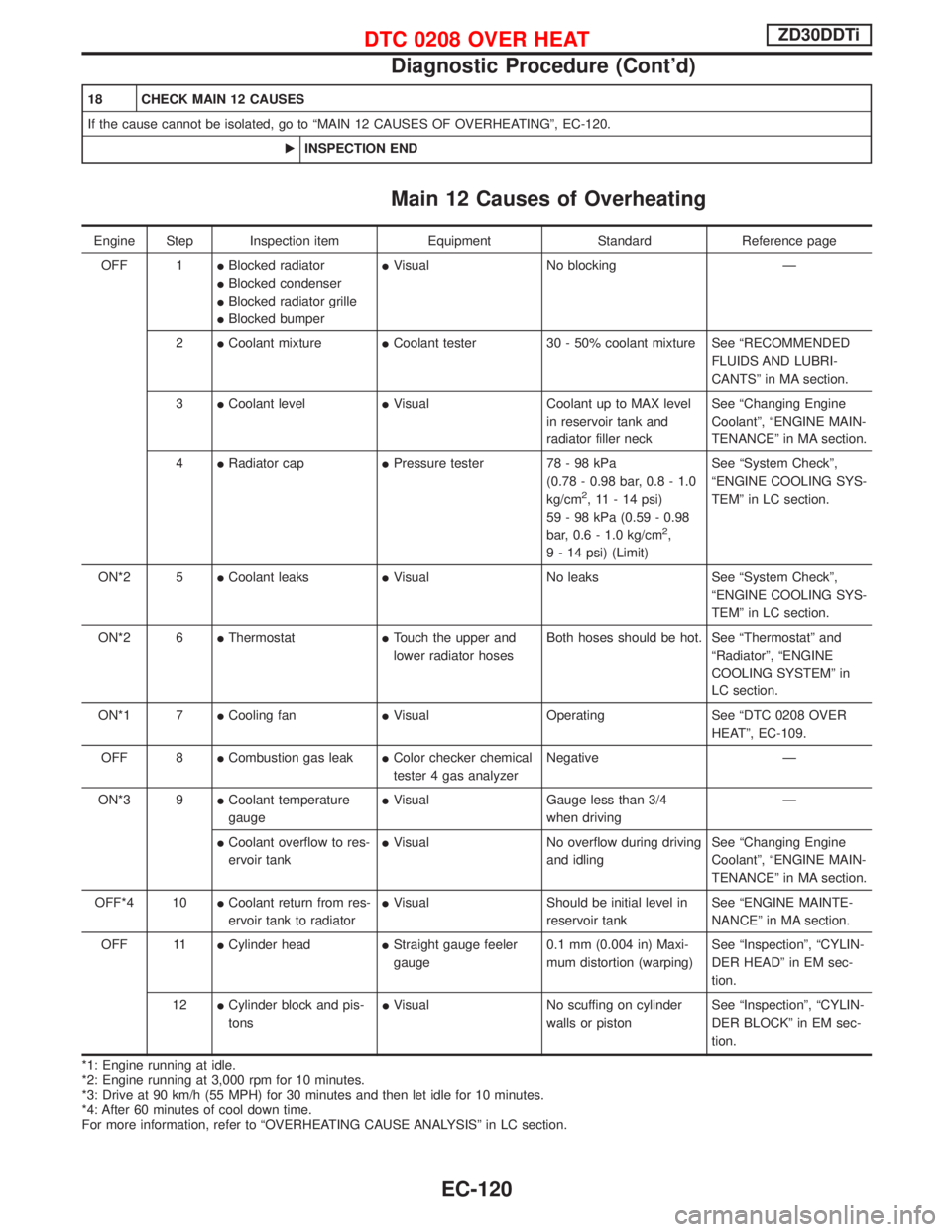
Main 12 Causes of Overheating
Engine Step Inspection item Equipment Standard Reference page
OFF 1IBlocked radiator
IBlocked condenser
IBlocked radiator grille
IBlocked bumperIVisual No blocking Ð
2ICoolant mixtureICoolant tester 30 - 50% coolant mixture See ªRECOMMENDED
FLUIDS AND LUBRI-
CANTSº in MA section.
3ICoolant levelIVisual Coolant up to MAX level
in reservoir tank and
radiator filler neckSee ªChanging Engine
Coolantº, ªENGINE MAIN-
TENANCEº in MA section.
4IRadiator capIPressure tester 78 - 98 kPa
(0.78 - 0.98 bar, 0.8 - 1.0
kg/cm
2, 11 - 14 psi)
59 - 98 kPa (0.59 - 0.98
bar, 0.6 - 1.0 kg/cm
2,
9 - 14 psi) (Limit)See ªSystem Checkº,
ªENGINE COOLING SYS-
TEMº in LC section.
ON*2 5ICoolant leaksIVisual No leaks See ªSystem Checkº,
ªENGINE COOLING SYS-
TEMº in LC section.
ON*2 6IThermostatITouch the upper and
lower radiator hosesBoth hoses should be hot. See ªThermostatº and
ªRadiatorº, ªENGINE
COOLING SYSTEMº in
LC section.
ON*1 7ICooling fanIVisual Operating See ªDTC 0208 OVER
HEATº, EC-109.
OFF 8ICombustion gas leakIColor checker chemical
tester 4 gas analyzerNegative Ð
ON*3 9ICoolant temperature
gaugeIVisual Gauge less than 3/4
when drivingÐ
ICoolant overflow to res-
ervoir tankIVisual No overflow during driving
and idlingSee ªChanging Engine
Coolantº, ªENGINE MAIN-
TENANCEº in MA section.
OFF*4 10ICoolant return from res-
ervoir tank to radiatorIVisual Should be initial level in
reservoir tankSee ªENGINE MAINTE-
NANCEº in MA section.
OFF 11ICylinder headIStraight gauge feeler
gauge0.1 mm (0.004 in) Maxi-
mum distortion (warping)See ªInspectionº, ªCYLIN-
DER HEADº in EM sec-
tion.
12ICylinder block and pis-
tonsIVisual No scuffing on cylinder
walls or pistonSee ªInspectionº, ªCYLIN-
DER BLOCKº in EM sec-
tion.
*1: Engine running at idle.
*2: Engine running at 3,000 rpm for 10 minutes.
*3: Drive at 90 km/h (55 MPH) for 30 minutes and then let idle for 10 minutes.
*4: After 60 minutes of cool down time.
For more information, refer to ªOVERHEATING CAUSE ANALYSISº in LC section.
DTC 0208 OVER HEATZD30DDTi
Diagnostic Procedure (Cont'd)
EC-120
Page 780 of 1767
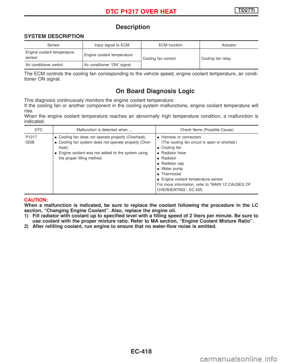
Description
SYSTEM DESCRIPTION
Sensor Input signal to ECM ECM function Actuator
Engine coolant temperature
sensorEngine coolant temperature
Cooling fan control Cooling fan relay
Air conditioner switch Air conditioner ªONº signal
The ECM controls the cooling fan corresponding to the vehicle speed, engine coolant temperature, air condi-
tioner ON signal.
On Board Diagnosis Logic
This diagnosis continuously monitors the engine coolant temperature.
If the cooling fan or another component in the cooling system malfunctions, engine coolant temperature will
rise.
When the engine coolant temperature reaches an abnormally high temperature condition, a malfunction is
indicated.
DTC Malfunction is detected when ... Check Items (Possible Cause)
P1217
0208ICooling fan does not operate properly (Overheat).
ICooling fan system does not operate properly (Over-
heat).
IEngine coolant was not added to the system using
the proper filling method.IHarness or connectors
(The cooling fan circuit is open or shorted.)
ICooling fan
IRadiator hose
IRadiator
IRadiator cap
IWater pump
IThermostat
IEngine coolant temperature sensor
For more information, refer to ªMAIN 12 CAUSES OF
OVERHEATINGº, EC-425.
CAUTION:
When a malfunction is indicated, be sure to replace the coolant following the procedure in the LC
section, ªChanging Engine Coolantº. Also, replace the engine oil.
1) Fill radiator with coolant up to specified level with a filling speed of 2 liters per minute. Be sure to
use coolant with the proper mixture ratio. Refer to MA section, ªEngine Coolant Mixture Ratioº.
2) After refilling coolant, run engine to ensure that no water-flow noise is emitted.
DTC P1217 OVER HEATTD27Ti
EC-418
Page 786 of 1767
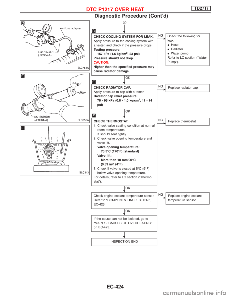
qc
CHECK COOLING SYSTEM FOR LEAK.
Apply pressure to the cooling system with
a tester, and check if the pressure drops.
Testing pressure:
157 kPa (1.6 kg/cm
2, 23 psi)
Pressure should not drop.
CAUTION:
Higher than the specified pressure may
cause radiator damage.
OK
ENG
Check the following for
leak.
IHose
IRadiator
IWater pump
Refer to LC section (ªWater
Pumpº).
CHECK RADIATOR CAP.
Apply pressure to cap with a tester.
Radiator cap relief pressure:
78 - 98 kPa (0.8 - 1.0 kg/cm
2,11-14
psi)
OK
ENG
Replace radiator cap.
CHECK THERMOSTAT.
1. Check valve seating condition at normal
room temperatures.
It should seat tightly.
2. Check valve opening temperature and
valve lift.
Valve opening temperature:
76.5ÉC (170ÉF) [standard]
Valve lift:
More than 10 mm/90ÉC
(0.39 in/194ÉF)
3. Check if valve is closed at 5ÉC (9ÉF)
below valve opening temperature.
For details, refer to LC section (ªThermo-
statº).
OK
ENG
Replace thermostat
Check engine coolant temperature sensor.
Refer to ªCOMPONENT INSPECTIONº,
EC-426.
OK
ENG
Replace engine coolant
temperature sensor.
If the cause can not be isolated, go to
ªMAIN 12 CAUSES OF OVERHEATINGº
on EC-425.
INSPECTION END
SLC754A
SLC755A
SLC343
H
H
H
H
H
H
DTC P1217 OVER HEATTD27Ti
Diagnostic Procedure (Cont'd)
EC-424
Page 787 of 1767
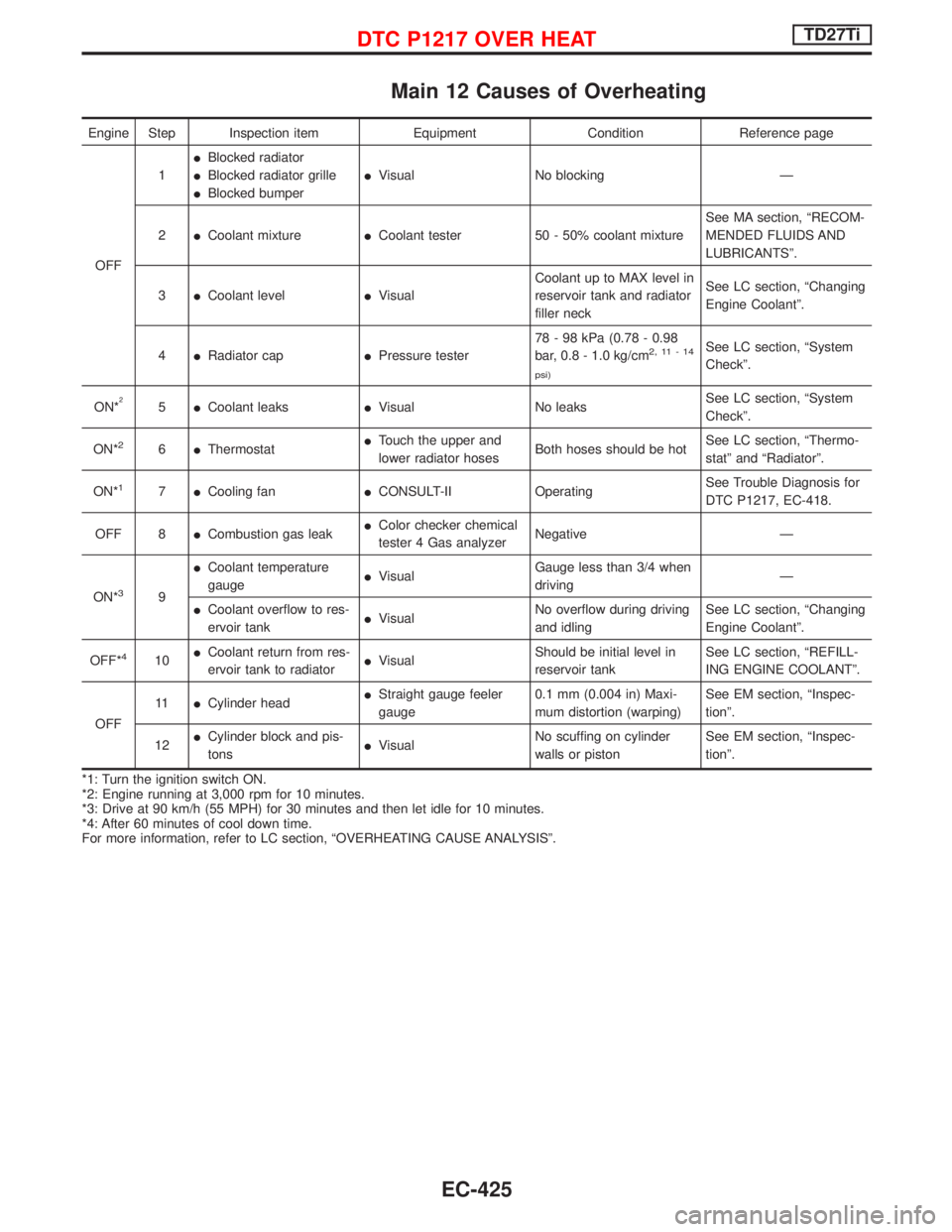
Main 12 Causes of Overheating
Engine Step Inspection item Equipment Condition Reference page
OFF1IBlocked radiator
IBlocked radiator grille
IBlocked bumperIVisual No blocking Ð
2ICoolant mixtureICoolant tester 50 - 50% coolant mixtureSee MA section, ªRECOM-
MENDED FLUIDS AND
LUBRICANTSº.
3ICoolant levelIVisualCoolant up to MAX level in
reservoir tank and radiator
filler neckSee LC section, ªChanging
Engine Coolantº.
4IRadiator capIPressure tester78 - 98 kPa (0.78 - 0.98
bar, 0.8 - 1.0 kg/cm
2,11-14
psi)See LC section, ªSystem
Checkº.
ON*
25ICoolant leaksIVisual No leaksSee LC section, ªSystem
Checkº.
ON*
26IThermostatITouch the upper and
lower radiator hosesBoth hoses should be hotSee LC section, ªThermo-
statº and ªRadiatorº.
ON*
17ICooling fanICONSULT-II OperatingSee Trouble Diagnosis for
DTC P1217, EC-418.
OFF 8ICombustion gas leakIColor checker chemical
tester 4 Gas analyzerNegative Ð
ON*
39ICoolant temperature
gaugeIVisualGauge less than 3/4 when
drivingÐ
ICoolant overflow to res-
ervoir tankIVisualNo overflow during driving
and idlingSee LC section, ªChanging
Engine Coolantº.
OFF*
410ICoolant return from res-
ervoir tank to radiatorIVisualShould be initial level in
reservoir tankSee LC section, ªREFILL-
ING ENGINE COOLANTº.
OFF11ICylinder headIStraight gauge feeler
gauge0.1 mm (0.004 in) Maxi-
mum distortion (warping)See EM section, ªInspec-
tionº.
12ICylinder block and pis-
tonsIVisualNo scuffing on cylinder
walls or pistonSee EM section, ªInspec-
tionº.
*1: Turn the ignition switch ON.
*2: Engine running at 3,000 rpm for 10 minutes.
*3: Drive at 90 km/h (55 MPH) for 30 minutes and then let idle for 10 minutes.
*4: After 60 minutes of cool down time.
For more information, refer to LC section, ªOVERHEATING CAUSE ANALYSISº.
DTC P1217 OVER HEATTD27Ti
EC-425