ad blue NISSAN TERRANO 2002 Service Repair Manual
[x] Cancel search | Manufacturer: NISSAN, Model Year: 2002, Model line: TERRANO, Model: NISSAN TERRANO 2002Pages: 1767, PDF Size: 41.51 MB
Page 601 of 1767
Description
SYSTEM DESCRIPTION
Sensor Input Signal to ECMECM
FunctionActuator
Crankshaft position
sensor (TDC)Engine speed
Glow
controlGlow lamp,
Glow relay
"
Glow plugs Engine coolant tem-
perature sensorEngine coolant tem-
perature
When engine coolant temperature is more than approximately 75ÉC
(167ÉF), the glow relay turns off, inactivating the quick-glow control
until coolant temperature drops below approximately 55ÉC (131ÉF).
When coolant temperature is lower than approximately 75ÉC
(167ÉF):
IIgnition switch ON
After ignition switch has turned to ON, the glow relay turns ON
for a certain period of time in relation to engine coolant
temperature, allowing current to flow through glow plug.
ICranking
The glow relay turns ON, allowing current to flow through glow
plug.
IStarting
After engine has started, current continues to flow through glow
plug (after-glow mode) for a certain period in relation to engine
coolant temperature.
When engine speed exceeds approximately 4,800 rpm, current
flow through glow plug is interrupted.
The glow indicator lamp turns ON for a certain period of time in
relation to engine coolant temperature at the time glow relay is
turned ON.
COMPONENT DESCRIPTION
Glow plug
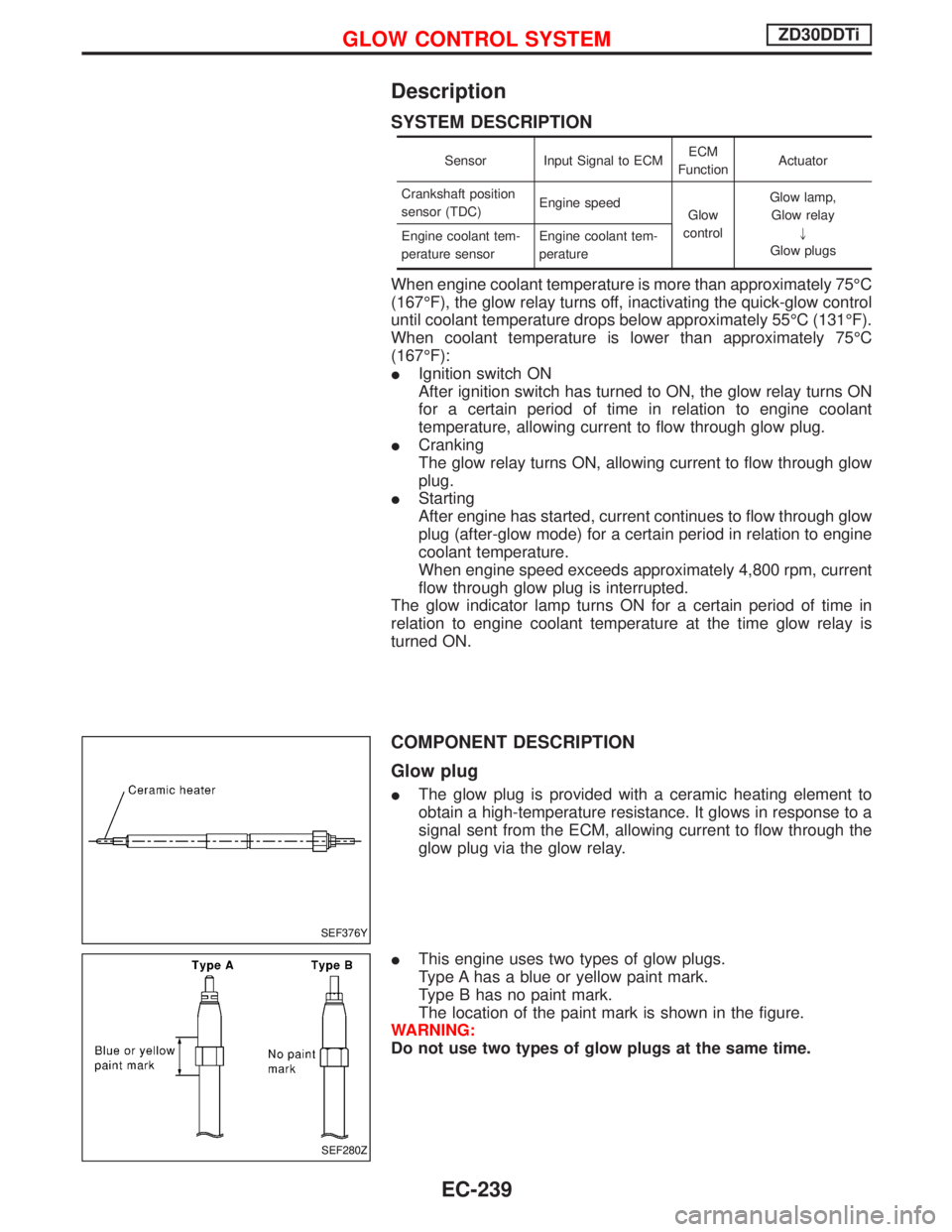
IThe glow plug is provided with a ceramic heating element to
obtain a high-temperature resistance. It glows in response to a
signal sent from the ECM, allowing current to flow through the
glow plug via the glow relay.
IThis engine uses two types of glow plugs.
Type A has a blue or yellow paint mark.
Type B has no paint mark.
The location of the paint mark is shown in the figure.
WARNING:
Do not use two types of glow plugs at the same time.
SEF376Y
SEF280Z
GLOW CONTROL SYSTEMZD30DDTi
EC-239
Page 1228 of 1767
Condition 3: Excessively high oil consumption, or exhaust shows pale blue smoke
Probable cause Corrective action
Oil leak at the connection of lubricating oil passage.
ECorrect the connection.
Oil leak at oil seal of turbine.E
Replace turbocharger assembly.Oil leak at oil seal of compressor.E
Worn journal or bearing.E
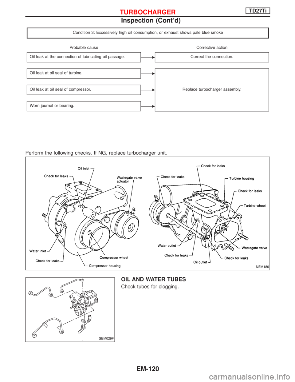
Perform the following checks. If NG, replace turbocharger unit.
OIL AND WATER TUBES
Check tubes for clogging.
NEM180
SEM029F
TURBOCHARGERTD27Ti
Inspection (Cont'd)
EM-120
Page 1327 of 1767
Description
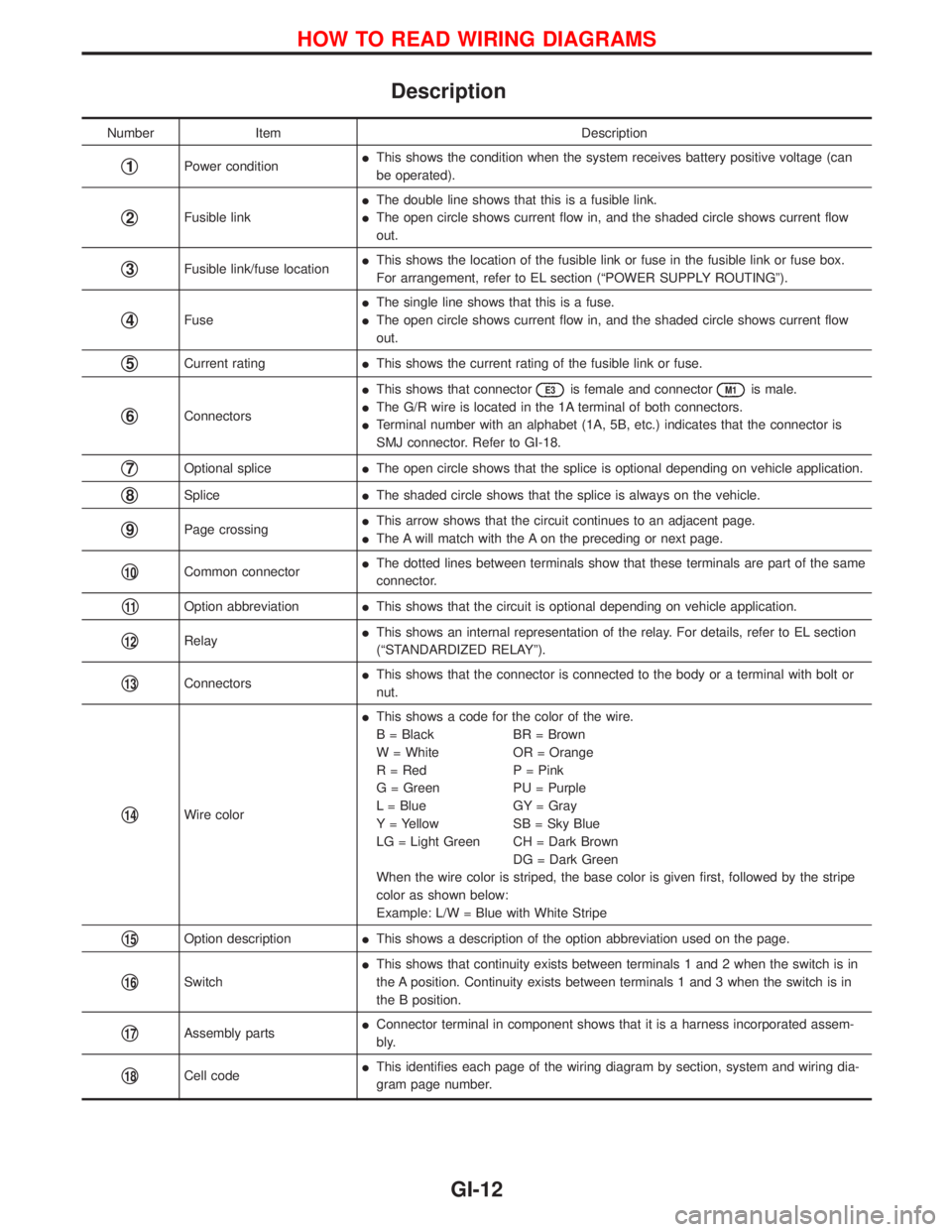
Number Item Description
q1Power conditionIThis shows the condition when the system receives battery positive voltage (can
be operated).
q2Fusible linkIThe double line shows that this is a fusible link.
IThe open circle shows current flow in, and the shaded circle shows current flow
out.
q3Fusible link/fuse locationIThis shows the location of the fusible link or fuse in the fusible link or fuse box.
For arrangement, refer to EL section (ªPOWER SUPPLY ROUTINGº).
q4FuseIThe single line shows that this is a fuse.
IThe open circle shows current flow in, and the shaded circle shows current flow
out.
q5Current ratingIThis shows the current rating of the fusible link or fuse.
q6ConnectorsIThis shows that connector
E3is female and connectorM1is male.
IThe G/R wire is located in the 1A terminal of both connectors.
ITerminal number with an alphabet (1A, 5B, etc.) indicates that the connector is
SMJ connector. Refer to GI-18.
q7Optional spliceIThe open circle shows that the splice is optional depending on vehicle application.
q8SpliceIThe shaded circle shows that the splice is always on the vehicle.
q9Page crossingIThis arrow shows that the circuit continues to an adjacent page.
IThe A will match with the A on the preceding or next page.
q10Common connectorIThe dotted lines between terminals show that these terminals are part of the same
connector.
q11Option abbreviationIThis shows that the circuit is optional depending on vehicle application.
q12RelayIThis shows an internal representation of the relay. For details, refer to EL section
(ªSTANDARDIZED RELAYº).
q13ConnectorsIThis shows that the connector is connected to the body or a terminal with bolt or
nut.
q14Wire colorIThis shows a code for the color of the wire.
B = Black BR = Brown
W = White OR = Orange
R = Red P = Pink
G = Green PU = Purple
L = Blue GY = Gray
Y = Yellow SB = Sky Blue
LG = Light Green CH = Dark Brown
DG = Dark Green
When the wire color is striped, the base color is given first, followed by the stripe
color as shown below:
Example: L/W = Blue with White Stripe
q15Option descriptionIThis shows a description of the option abbreviation used on the page.
q16SwitchIThis shows that continuity exists between terminals 1 and 2 when the switch is in
the A position. Continuity exists between terminals 1 and 3 when the switch is in
the B position.
q17Assembly partsIConnector terminal in component shows that it is a harness incorporated assem-
bly.
q18Cell codeIThis identifies each page of the wiring diagram by section, system and wiring dia-
gram page number.
HOW TO READ WIRING DIAGRAMS
GI-12
Page 1364 of 1767
HFC-134a (R-134a) Service Tools and
Equipment
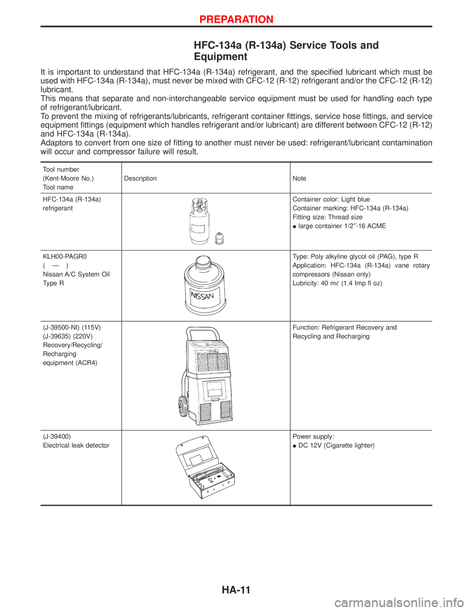
It is important to understand that HFC-134a (R-134a) refrigerant, and the specified lubricant which must be
used with HFC-134a (R-134a), must never be mixed with CFC-12 (R-12) refrigerant and/or the CFC-12 (R-12)
lubricant.
This means that separate and non-interchangeable service equipment must be used for handling each type
of refrigerant/lubricant.
To prevent the mixing of refrigerants/lubricants, refrigerant container fittings, service hose fittings, and service
equipment fittings (equipment which handles refrigerant and/or lubricant) are different between CFC-12 (R-12)
and HFC-134a (R-134a).
Adaptors to convert from one size of fitting to another must never be used: refrigerant/lubricant contamination
will occur and compressor failure will result.
Tool number
(Kent-Moore No.)
Tool nameDescription Note
HFC-134a (R-134a)
refrigerant
Container color: Light blue
Container marking: HFC-134a (R-134a)
Fitting size: Thread size
Ilarge container 1/2²-16 ACME
KLH00-PAGR0
(Ð)
Nissan A/C System Oil
Type R
Type: Poly alkyline glycol oil (PAG), type R
Application: HFC-134a (R-134a) vane rotary
compressors (Nissan only)
Lubricity: 40 m(1.4 Imp fl oz)
(J-39500-NI) (115V)
(J-39635) (220V)
Recovery/Recycling/
Recharging
equipment (ACR4)
Function: Refrigerant Recovery and
Recycling and Recharging
(J-39400)
Electrical leak detector
Power supply:
IDC 12V (Cigarette lighter)
PREPARATION
HA-11
Page 1365 of 1767
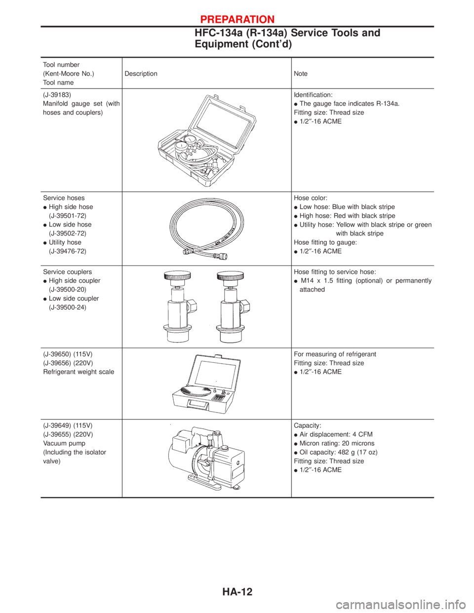
Tool number
(Kent-Moore No.)
Tool nameDescription Note
(J-39183)
Manifold gauge set (with
hoses and couplers)
Identification:
IThe gauge face indicates R-134a.
Fitting size: Thread size
I1/2²-16 ACME
Service hoses
IHigh side hose
(J-39501-72)
ILow side hose
(J-39502-72)
IUtility hose
(J-39476-72)
Hose color:
ILow hose: Blue with black stripe
IHigh hose: Red with black stripe
IUtility hose: Yellow with black stripe or green
with black stripe
Hose fitting to gauge:
I1/2²-16 ACME
Service couplers
IHigh side coupler
(J-39500-20)
ILow side coupler
(J-39500-24)
Hose fitting to service hose:
IM14 x 1.5 fitting (optional) or permanently
attached
(J-39650) (115V)
(J-39656) (220V)
Refrigerant weight scale
For measuring of refrigerant
Fitting size: Thread size
I1/2²-16 ACME
(J-39649) (115V)
(J-39655) (220V)
Vacuum pump
(Including the isolator
valve)
Capacity:
IAir displacement: 4 CFM
IMicron rating: 20 microns
IOil capacity: 482 g (17 oz)
Fitting size: Thread size
I1/2²-16 ACME
PREPARATION
HFC-134a (R-134a) Service Tools and
Equipment (Cont'd)
HA-12
Page 1602 of 1767
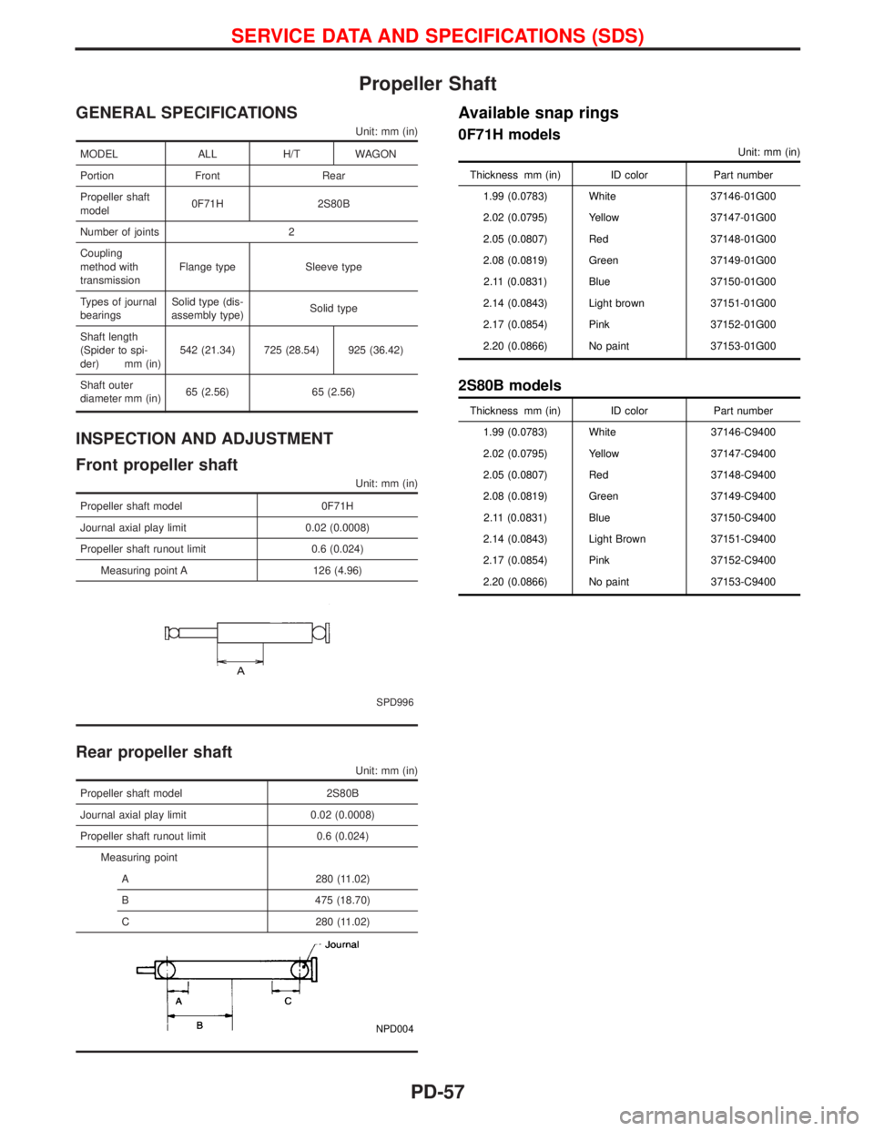
Propeller Shaft
GENERAL SPECIFICATIONS
Unit: mm (in)
MODEL ALL H/T WAGON
Portion Front Rear
Propeller shaft
model0F71H 2S80B
Number of joints 2
Coupling
method with
transmissionFlange type Sleeve type
Types of journal
bearingsSolid type (dis-
assembly type)Solid type
Shaft length
(Spider to spi-
der) mm (in)542 (21.34) 725 (28.54) 925 (36.42)
Shaft outer
diameter mm (in)65 (2.56) 65 (2.56)
INSPECTION AND ADJUSTMENT
Front propeller shaft
Unit: mm (in)
Propeller shaft model 0F71H
Journal axial play limit 0.02 (0.0008)
Propeller shaft runout limit 0.6 (0.024)
Measuring point A 126 (4.96)
SPD996
Rear propeller shaft
Unit: mm (in)
Propeller shaft model 2S80B
Journal axial play limit 0.02 (0.0008)
Propeller shaft runout limit 0.6 (0.024)
Measuring point
A 280 (11.02)
B 475 (18.70)
C 280 (11.02)
NPD004
Available snap rings
0F71H models
Unit: mm (in)
Thickness mm (in) ID color Part number
1.99 (0.0783) White 37146-01G00
2.02 (0.0795) Yellow 37147-01G00
2.05 (0.0807) Red 37148-01G00
2.08 (0.0819) Green 37149-01G00
2.11 (0.0831) Blue 37150-01G00
2.14 (0.0843) Light brown 37151-01G00
2.17 (0.0854) Pink 37152-01G00
2.20 (0.0866) No paint 37153-01G00
2S80B models
Thickness mm (in) ID color Part number
1.99 (0.0783) White 37146-C9400
2.02 (0.0795) Yellow 37147-C9400
2.05 (0.0807) Red 37148-C9400
2.08 (0.0819) Green 37149-C9400
2.11 (0.0831) Blue 37150-C9400
2.14 (0.0843) Light Brown 37151-C9400
2.17 (0.0854) Pink 37152-C9400
2.20 (0.0866) No paint 37153-C9400
SERVICE DATA AND SPECIFICATIONS (SDS)
PD-57