window NISSAN TERRANO 2002 Service Repair Manual
[x] Cancel search | Manufacturer: NISSAN, Model Year: 2002, Model line: TERRANO, Model: NISSAN TERRANO 2002Pages: 1767, PDF Size: 41.51 MB
Page 289 of 1767
BODY & TRIM
SECTION
BT
CONTENTS
PRECAUTIONS...............................................................2
Service Notice..............................................................2
Supplemental Restraint System (SRS)²AIR
BAG²and²SEAT BELT PRE-TENSIONER²...............2
CLIP AND FASTENER....................................................3
Description ...................................................................3
CHASSIS AND BODY MAINTENANCE.........................5
Checking Body Corrosion ............................................5
BODY FRONT END.........................................................6
Removal and Installation .............................................6
BODY REAR END AND OPENER..................................8
Removal and Installation .............................................8
DOOR.............................................................................10
Removal and Installation ...........................................10
INSTRUMENT PANEL ASSEMBLY..............................16
Removal and Installation ...........................................16
SIDE AND FLOOR TRIM..............................................18
Removal and Installation ...........................................18
DOOR TRIM...................................................................19
Removal and Installation ...........................................19ROOF TRIM...................................................................20
Removal and Installation ...........................................20
EXTERIOR.....................................................................21
Removal and Installation ...........................................21
FRONT SEAT.................................................................34
Removal and Installation ...........................................34
Heated Seat ...............................................................36
Active Head Restraint ................................................36
SECOND SEAT..............................................................37
Removal and Installation ...........................................37
THIRD SEAT..................................................................39
Removal and Installation ...........................................39
SUNROOF......................................................................40
Removal and Installation ...........................................40
WINDSHIELD AND WINDOWS....................................42
Removal and Installation ...........................................42
DOOR MIRROR.............................................................48
Removal and Installation ...........................................48
BODY (ALIGNMENT)....................................................49
Alignment ...................................................................49
Page 330 of 1767
Removal and Installation
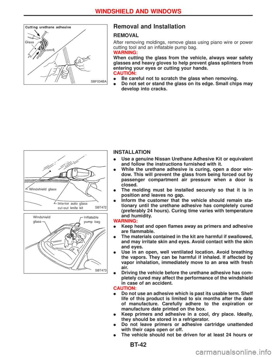
REMOVAL
After removing moldings, remove glass using piano wire or power
cutting tool and an inflatable pump bag.
WARNING:
When cutting the glass from the vehicle, always wear safety
glasses and heavy gloves to help prevent glass splinters from
entering your eyes or cutting your hands.
CAUTION:
IBe careful not to scratch the glass when removing.
IDo not set or stand the glass on its edge. Small chips may
develop into cracks.
INSTALLATION
IUse a genuine Nissan Urethane Adhesive Kit or equivalent
and follow the instructions furnished with it.
IWhile the urethane adhesive is curing, open a door win-
dow. This will prevent the glass from being forced out by
passenger compartment air pressure when a door is
closed.
IThe molding must be installed securely so that it is in
position and leaves no gap.
IInform the customer that the vehicle should remain sta-
tionary until the urethane adhesive has completely cured
(preferably 24 hours). Curing time varies with temperature
and humidity.
WARNING:
IKeep heat and open flames away as primers and adhesive
are flammable.
IThe materials contained in the kit are harmful if swallowed,
and may irritate skin and eyes. Avoid contact with the skin
and eyes.
IUse in an open, well ventilated location. Avoid breathing
the vapors. They can be harmful if inhaled. If affected by
vapor inhalation, immediately move to an area with fresh
air.
IDriving the vehicle before the urethane adhesive has com-
pletely cured may affect the performance of the windshield
in case of an accident.
CAUTION:
IDo not use an adhesive which is past its usable term. Shelf
life of this product is limited to six months after the date
of manufacture. Carefully adhere to the expiration or
manufacture date printed on the box.
IKeep primers and adhesive in a cool, dry place. Ideally,
they should be stored in a refrigerator.
IDo not leave primers or adhesive cartridge unattended
with their caps open or off.
IThe vehicle should not be driven for at least 24 hours or
SBF034BA
SBT472
SBT473
WINDSHIELD AND WINDOWS
BT-42
Page 331 of 1767
until the urethane adhesive has completely cured. Curing
time varies depending on temperature and humidities. The
curing time will increase under higher temperatures and
lower humidities.
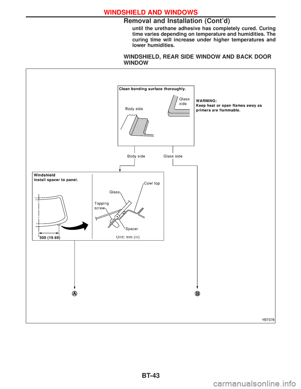
WINDSHIELD, REAR SIDE WINDOW AND BACK DOOR
WINDOW
YBT078
WINDSHIELD AND WINDOWS
Removal and Installation (Cont'd)
BT-43
Page 332 of 1767
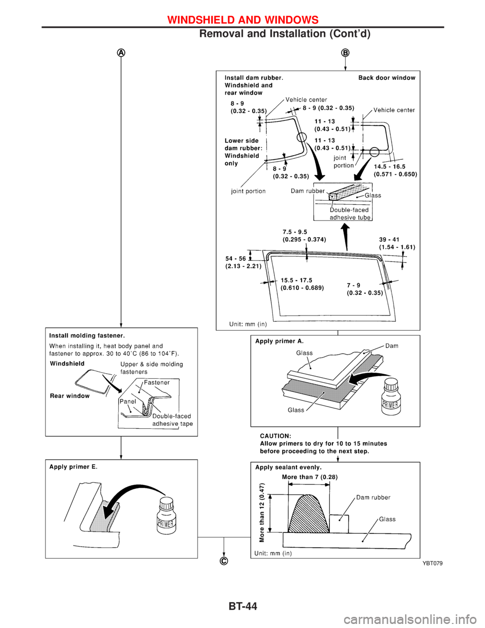
YBT079
WINDSHIELD AND WINDOWS
Removal and Installation (Cont'd)
BT-44
Page 333 of 1767
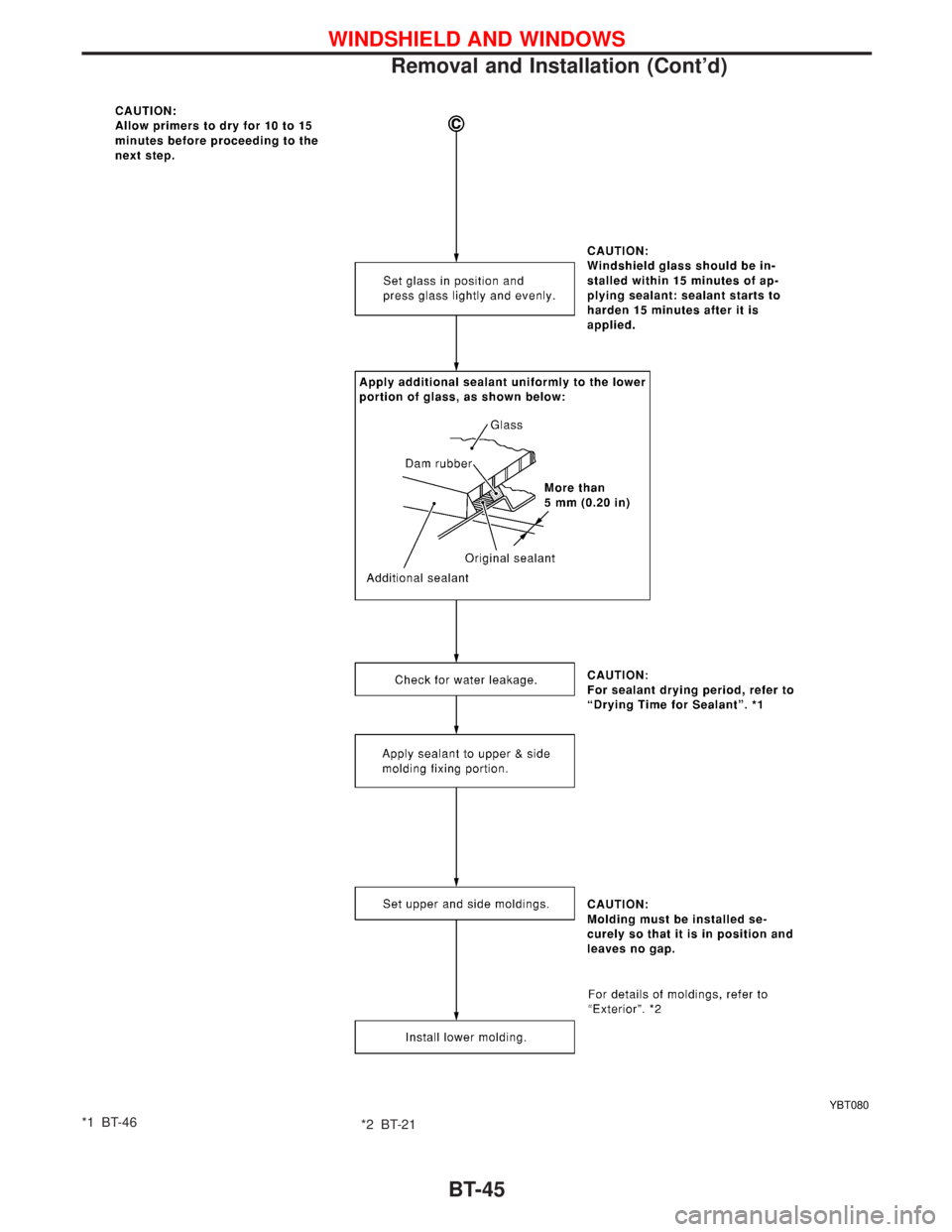
*1 BT-46
*2 BT-21
YBT080
WINDSHIELD AND WINDOWS
Removal and Installation (Cont'd)
BT-45
Page 334 of 1767
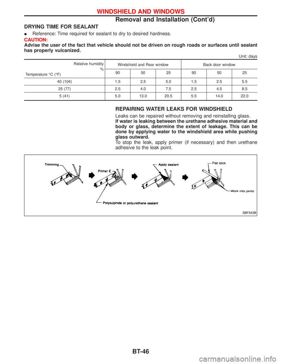
DRYING TIME FOR SEALANT
IReference: Time required for sealant to dry to desired hardness.
CAUTION:
Advise the user of the fact that vehicle should not be driven on rough roads or surfaces until sealant
has properly vulcanized.
Unit: days
Relative humidity
%
Temperature ÉC (ÉF)Windshield and Rear window Back door window
90 50 25 90 50 25
40 (104) 1.5 2.5 5.0 1.5 2.5 5.5
25 (77) 2.5 4.0 7.5 2.5 4.5 8.5
5 (41) 5.0 13.0 20.5 5.5 14.0 22.0
REPAIRING WATER LEAKS FOR WINDSHIELD
Leaks can be repaired without removing and reinstalling glass.
If water is leaking between the urethane adhesive material and
body or glass, determine the extent of leakage. This can be
done by applying water to the windshield area while pushing
glass outward.
To stop the leak, apply primer (if necessary) and then urethane
adhesive to the leak point.
SBF543B
WINDSHIELD AND WINDOWS
Removal and Installation (Cont'd)
BT-46
Page 335 of 1767
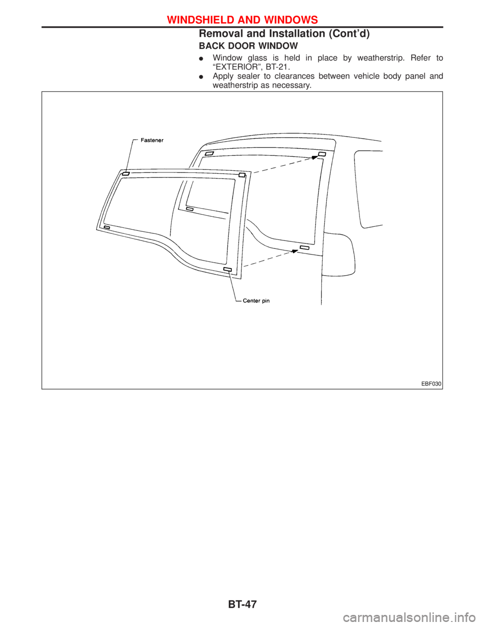
BACK DOOR WINDOW
IWindow glass is held in place by weatherstrip. Refer to
ªEXTERIORº, BT-21.
IApply sealer to clearances between vehicle body panel and
weatherstrip as necessary.
EBF030
WINDSHIELD AND WINDOWS
Removal and Installation (Cont'd)
BT-47
Page 817 of 1767

ELECTRICAL SYSTEM
SECTION
EL
When you read wiring diagrams:
IRead GI section, ªHOW TO READ WIRING DIAGRAMSº.
CONTENTS
HARNESS CONNECTOR................................................3
Description ...................................................................3
STANDARDIZED RELAYS..............................................4
Description ...................................................................4
POWER SUPPLY ROUTING...........................................6
Schematic ....................................................................6
Wiring Diagram - POWER - ........................................8
Fuse ...........................................................................17
Fusible Link................................................................17
Circuit Breaker Inspection .........................................17
GROUND DISTRIBUTION.............................................18
COMBINATION SWITCH...............................................23
Check .........................................................................23
Replacement ..............................................................24
STEERING SWITCH......................................................25
Check .........................................................................25
HEADLAMP - Without Daytime Light System -.........26
Wiring Diagram - H/LAMP -.......................................26
HEADLAMP - Daytime Light System -.......................29
Operation ...................................................................29
Schematic ..................................................................30
Wiring Diagram - DTRL - ...........................................31
HEADLAMP - Headlamp Aiming Control -.................37
Description .................................................................37
Replacing Headlamp Aiming Actuator .......................38
Wiring Diagram - H/AIM - ..........................................39
Trouble Diagnoses.....................................................42
HEADLAMP...................................................................43
Bulb Replacement .....................................................43
Aiming Adjustment .....................................................43
EXTERIOR LAMP..........................................................45
Wiring Diagram - TAIL/L - ..........................................45
Wiring Diagram - STOP/L - .......................................48
Wiring Diagram - BACK/L - .......................................49
Wiring Diagram - F/FOG - .........................................51
Front Fog Lamp Aiming Adjustment ..........................53
Wiring Diagram - R/FOG -.........................................54
Schematic ..................................................................55Wiring Diagram - TURN - ..........................................56
Bulb Specifications ....................................................60
INTERIOR LAMP...........................................................61
Schematic ..................................................................61
Wiring Diagram - ILL - ...............................................62
Wiring Diagram - INT/L - ...........................................66
METER AND GAUGES.................................................70
Combination Meter ....................................................70
Schematic ..................................................................71
Wiring Diagram - METER - .......................................72
Combination Meter Self-Diagnosis ............................76
Components Inspection .............................................78
Trouble Diagnoses.....................................................79
Fuel Tank Gauge Unit Check ....................................80
Thermal Transmitter Check .......................................80
Oil Pressure Switch Check ........................................80
WARNING LAMPS AND CHIME...................................81
Schematic ..................................................................81
Wiring Diagram - WARN - .........................................82
Diode Check ..............................................................92
Wiring Diagram - CHIME - ........................................93
WIPER AND WASHER..................................................94
Wiring Diagram - WIPER - ........................................94
Wiring Diagram - WIP/R -..........................................96
Installation ..................................................................98
Washer Nozzle Adjustment .......................................99
Check Valve ...............................................................99
Wiring Diagram - HLC - ...........................................100
HORN, CIGARETTE LIGHTER AND CLOCK............104
Wiring Diagram - HORN - .......................................104
Wiring Diagram - CIGAR -.......................................105
Wiring Diagram - CLOCK -......................................106
REAR WINDOW DEFOGGER AND DOOR
MIRROR DEFOGGER.................................................107
Wiring Diagram - DEF - ...........................................107
Filament Check ........................................................109
Filament Repair ....................................................... 110
AUDIO.......................................................................... 111
Page 818 of 1767
System Description .................................................. 111
Schematic ................................................................ 113
Wiring Diagram - AUDIO - ....................................... 115
Wiring Diagram - REMOTE -...................................122
Trouble Diagnoses...................................................124
Inspection.................................................................126
Location of Roof Mounted Antenna .........................127
HEATED SEAT............................................................128
Wiring Diagram - HSEAT - ......................................128
SUNROOF....................................................................130
Wiring Diagram - SROOF - .....................................130
DOOR MIRROR...........................................................131
Wiring Diagram - MIRROR - ...................................131
POWER WINDOW.......................................................133
Schematic ................................................................133
Wiring Diagram - WINDOW - ..................................134
POWER DOOR LOCK.................................................137
Power Door Lock .....................................................137
Schematic ................................................................138
Wiring Diagram - D/LOCK -.....................................140
POWER DOOR LOCK - SUPER LOCK -...................145
Component Parts Location ......................................145
System Description ..................................................146
Schematic ................................................................148
Wiring Diagram - S/LOCK - .....................................150
Trouble Diagnoses...................................................158
MULTI-REMOTE CONTROL SYSTEM.......................168
Schematic ................................................................168
Wiring Diagram - MULTI - .......................................169
Trouble Diagnoses...................................................177
ID Code Entry Procedure ........................................179
TIME CONTROL UNIT (TCU).....................................180
System Description ..................................................180Trouble Diagnosis ....................................................182
Schematic ................................................................184
NATS (Nissan Anti-Theft System).............................186
System Description ..................................................186
System Composition ................................................187
Component Parts Location ......................................188
Wiring Diagram - NATS -.........................................189
CONSULT-II .............................................................193
Trouble Diagnoses...................................................195
How to Replace NATS IMMU ..................................208
THEFT WARNING SYSTEM.......................................209
Components Parts and Harness Connector
Location ...................................................................209
System Description ..................................................210
Theft Warning System/Schematic ...........................213
Wiring Diagram - THEFT -.......................................214
Trouble Diagnoses...................................................230
LOCATION OF ELECTRICAL UNITS.........................241
Engine Compartment ...............................................241
Passenger Compartment/LHD Models ....................242
Passenger Compartment/RHD Models ...................244
HARNESS LAYOUT....................................................247
Outline......................................................................247
Main Harness...........................................................248
EFC Harness ...........................................................264
Engine Harness .......................................................276
Body Harness ..........................................................278
Chassis Harness......................................................286
Room Lamp Harness...............................................287
Tailgate Harness ......................................................288
Door Harness (LH side)...........................................289
Door Harness (RH side) ..........................................290
WIRING DIAGRAM CODES (CELL CODES).............291
WIRING DIAGRAM REFERENCE CHART
ENGINE CONTROL SYSTEM, IGNITION SYSTEM ................................................................................................EC SECTION
RESTRAINT SYSTEM (AIR BAG) ...........................................................................................................................RS SECTION
HEATER AND AIR CONDITIONER ..........................................................................................................................HA SECTION
CONTENTS(Cont'd)
EL-2
Page 834 of 1767
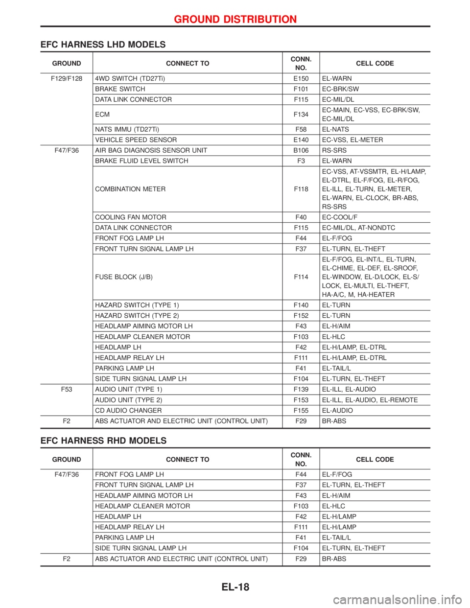
EFC HARNESS LHD MODELS
GROUND CONNECT TOCONN.
NO.CELL CODE
F129/F128 4WD SWITCH (TD27Ti) E150 EL-WARN
BRAKE SWITCH F101 EC-BRK/SW
DATA LINK CONNECTOR F115 EC-MIL/DL
ECM F134EC-MAIN, EC-VSS, EC-BRK/SW,
EC-MIL/DL
NATS IMMU (TD27Ti) F58 EL-NATS
VEHICLE SPEED SENSOR E140 EC-VSS, EL-METER
F47/F36 AIR BAG DIAGNOSIS SENSOR UNIT B106 RS-SRS
BRAKE FLUID LEVEL SWITCH F3 EL-WARN
COMBINATION METER F118EC-VSS, AT-VSSMTR, EL-H/LAMP,
EL-DTRL, EL-F/FOG, EL-R/FOG,
EL-ILL, EL-TURN, EL-METER,
EL-WARN, EL-CLOCK, BR-ABS,
RS-SRS
COOLING FAN MOTOR F40 EC-COOL/F
DATA LINK CONNECTOR F115 EC-MIL/DL, AT-NONDTC
FRONT FOG LAMP LH F44 EL-F/FOG
FRONT TURN SIGNAL LAMP LH F37 EL-TURN, EL-THEFT
FUSE BLOCK (J/B) F114EL-F/FOG, EL-INT/L, EL-TURN,
EL-CHIME, EL-DEF, EL-SROOF,
EL-WINDOW, EL-D/LOCK, EL-S/
LOCK, EL-MULTI, EL-THEFT,
HA-A/C, M, HA-HEATER
HAZARD SWITCH (TYPE 1) F140 EL-TURN
HAZARD SWITCH (TYPE 2) F152 EL-TURN
HEADLAMP AIMING MOTOR LH F43 EL-H/AIM
HEADLAMP CLEANER MOTOR F103 EL-HLC
HEADLAMP LH F42 EL-H/LAMP, EL-DTRL
HEADLAMP RELAY LH F111 EL-H/LAMP, EL-DTRL
PARKING LAMP LH F41 EL-TAIL/L
SIDE TURN SIGNAL LAMP LH F104 EL-TURN, EL-THEFT
F53 AUDIO UNIT (TYPE 1) F139 EL-ILL, EL-AUDIO
AUDIO UNIT (TYPE 2) F153 EL-ILL, EL-AUDIO, EL-REMOTE
CD AUDIO CHANGER F155 EL-AUDIO
F2 ABS ACTUATOR AND ELECTRIC UNIT (CONTROL UNIT) F29 BR-ABS
EFC HARNESS RHD MODELS
GROUND CONNECT TOCONN.
NO.CELL CODE
F47/F36 FRONT FOG LAMP LH F44 EL-F/FOG
FRONT TURN SIGNAL LAMP LH F37 EL-TURN, EL-THEFT
HEADLAMP AIMING MOTOR LH F43 EL-H/AIM
HEADLAMP CLEANER MOTOR F103 EL-HLC
HEADLAMP LH F42 EL-H/LAMP
HEADLAMP RELAY LH F111 EL-H/LAMP
PARKING LAMP LH F41 EL-TAIL/L
SIDE TURN SIGNAL LAMP LH F104 EL-TURN, EL-THEFT
F2 ABS ACTUATOR AND ELECTRIC UNIT (CONTROL UNIT) F29 BR-ABS
GROUND DISTRIBUTION
EL-18