sensor NISSAN TERRANO 2004 Service User Guide
[x] Cancel search | Manufacturer: NISSAN, Model Year: 2004, Model line: TERRANO, Model: NISSAN TERRANO 2004Pages: 1833, PDF Size: 53.42 MB
Page 120 of 1833
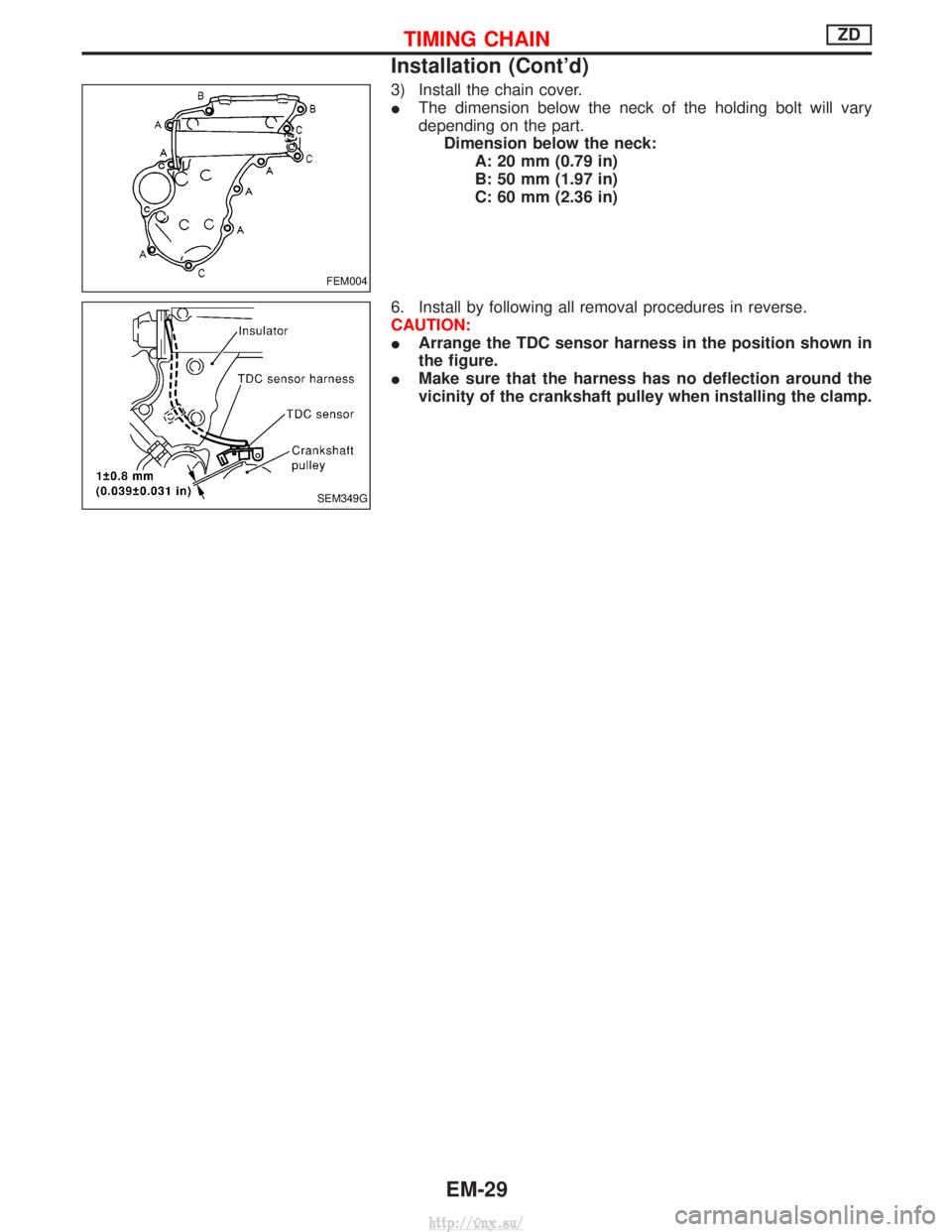
3) Install the chain cover.
IThe dimension below the neck of the holding bolt will vary
depending on the part.
Dimension below the neck: A: 20 mm (0.79 in)
B: 50 mm (1.97 in)
C: 60 mm (2.36 in)
6. Install by following all removal procedures in reverse.
CAUTION:
I Arrange the TDC sensor harness in the position shown in
the figure.
I Make sure that the harness has no deflection around the
vicinity of the crankshaft pulley when installing the clamp.
FEM004
SEM349G
TIMING CHAINZD
Installation (Cont'd)
EM-29
http://vnx.su/
Page 126 of 1833
Inspection
IWhen the camshaft or parts in connection with valves are
removed or replaced, and a fault has occurred (poor starting,
idling, or other faults) due to the misadjustment of the valve
clearance, inspect as follows.
I Inspect and adjust when the engine is cool (at normal tempera-
ture).
I Be careful of the intake and exhaust valve arrangement. (The
valve arrangement is different from that in a normal engine.)
(The camshafts have, alternately, either an intake valve or an
exhaust valve.)
1. Remove the following parts.
I Intercooler cover
I Intercooler
I Rocker cover
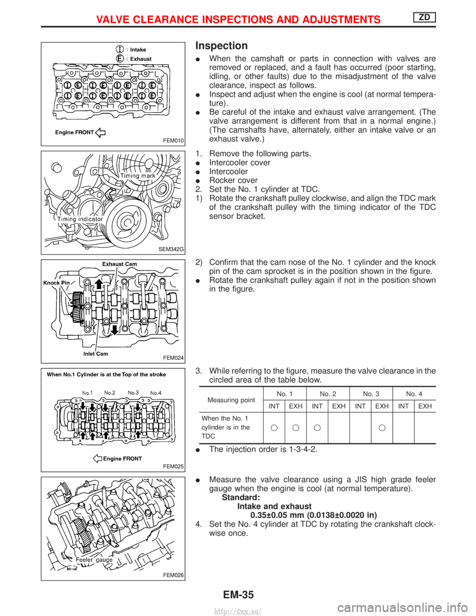
2. Set the No. 1 cylinder at TDC.
1) Rotate the crankshaft pulley clockwise, and align the TDC mark of the crankshaft pulley with the timing indicator of the TDC
sensor bracket.
2) Confirm that the cam nose of the No. 1 cylinder and the knock pin of the cam sprocket is in the position shown in the figure.
I Rotate the crankshaft pulley again if not in the position shown
in the figure.
3. While referring to the figure, measure the valve clearance in the circled area of the table below.
Measuring point No. 1 No. 2 No. 3 No. 4
INT EXH INT EXH INT EXH INT EXH
When the No. 1
cylinder is in the
TDC qqq q
I
The injection order is 1-3-4-2.
I Measure the valve clearance using a JIS high grade feeler
gauge when the engine is cool (at normal temperature).
Standard: Intake and exhaust0.35 0.05 mm (0.0138 0.0020 in)
4. Set the No. 4 cylinder at TDC by rotating the crankshaft clock- wise once.
FEM010
SEM342G
FEM024
FEM025
FEM026
VALVE CLEARANCE INSPECTIONS AND ADJUSTMENTSZD
EM-35
http://vnx.su/
Page 130 of 1833
Removal
1. Remove the engine assembly.Refer to ªENGINE REMOVALº, EM-63.
2. Place the engine on an engine stand (SST). Refer to ªCYLINDER BLOCKº, EM-67.
3. Remove the following.
I Auto tensioner bracket
I Air conditioner bracket
I Alternator bracket
I Oil tube
I Vacuum pump
I Rocker cover
I Oil pan (upper, lower)
I Injection tube
I Spill tube
I High pressure nozzle assembly
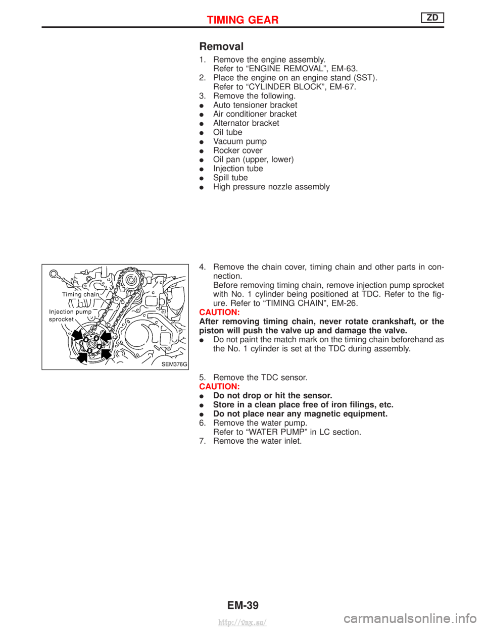
4. Remove the chain cover, timing chain and other parts in con- nection.
Before removing timing chain, remove injection pump sprocket
with No. 1 cylinder being positioned at TDC. Refer to the fig-
ure. Refer to ªTIMING CHAINº, EM-26.
CAUTION:
After removing timing chain, never rotate crankshaft, or the
piston will push the valve up and damage the valve.
I Do not paint the match mark on the timing chain beforehand as
the No. 1 cylinder is set at the TDC during assembly.
5. Remove the TDC sensor.
CAUTION:
I Do not drop or hit the sensor.
I Store in a clean place free of iron filings, etc.
I Do not place near any magnetic equipment.
6. Remove the water pump. Refer to ªWATER PUMPº in LC section.
7. Remove the water inlet.
SEM376G
TIMING GEARZD
EM-39
http://vnx.su/
Page 139 of 1833
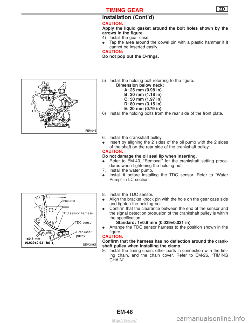
CAUTION:
Apply the liquid gasket around the bolt holes shown by the
arrows in the figure.
4) Install the gear case.
ITap the area around the dowel pin with a plastic hammer if it
cannot be inserted easily.
CAUTION:
Do not pop out the O-rings.
5) Install the holding bolt referring to the figure. Dimension below neck:A: 25 mm (0.98 in)
B: 30 mm (1.18 in)
C: 50 mm (1.97 in)
D: 80 mm (3.15 in)
E: 20 mm (0.79 in)
6) Install the holding bolts from the rear side of the front plate.
6. Install the crankshaft pulley.
I Insert by aligning the 2 sides of the oil pump with the 2 sides
of the shaft on the rear side of the crankshaft pulley.
CAUTION:
Do not damage the oil seal lip when inserting.
I Refer to EM-40, ªRemovalº for the crankshaft setting proce-
dures when tightening the holding nut.
7. Install the water pump.
I Install it before installing the TDC sensor. Refer to ªWater
Pumpº in LC section.
8. Install the TDC sensor.
I Align the bracket knock pin with the hole on the gear case side
and tighten the holding bolt.
I Confirm that the clearance between the end of the sensor and
the signal detection protrusion of the crankshaft pulley is within
the specification.
Standard: 1 0.8 mm (0.039 0.031 in)
I Arrange the TDC sensor harness to the position shown in the
figure.
CAUTION:
Confirm that the harness has no deflection around the crank-
shaft pulley when installing the clamp.
9. Install the timing chain, other parts in connection with the tim- ing chain, and the chain cover. Refer to EM-26, ªTIMING
CHAINº.
FEM046
SEM349G
TIMING GEARZD
Installation (Cont'd)
EM-48
http://vnx.su/
Page 191 of 1833
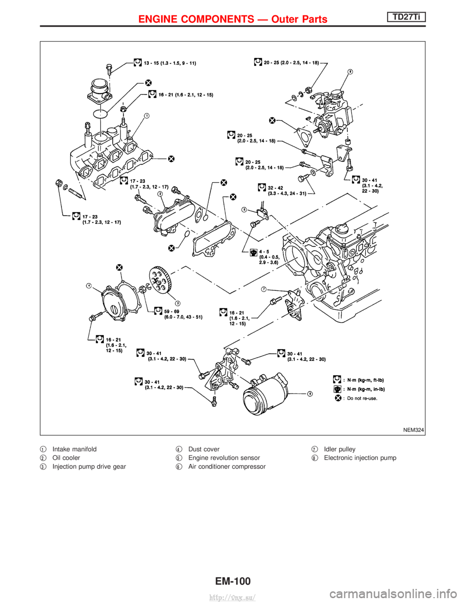
q1Intake manifold
q
2Oil cooler
q
3Injection pump drive gear q
4Dust cover
q
5Engine revolution sensor
q
6Air conditioner compressor q
7Idler pulley
q
8Electronic injection pump
NEM324
ENGINE COMPONENTS Ð Outer PartsTD27Ti
EM-100
http://vnx.su/
Page 252 of 1833
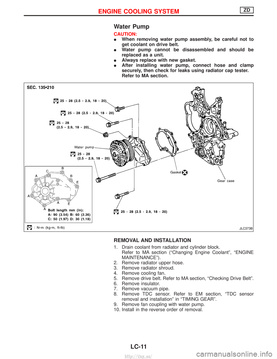
Water Pump
CAUTION:
IWhen removing water pump assembly, be careful not to
get coolant on drive belt.
I Water pump cannot be disassembled and should be
replaced as a unit.
I Always replace with new gasket.
I After installing water pump, connect hose and clamp
securely, then check for leaks using radiator cap tester.
Refer to MA section.
REMOVAL AND INSTALLATION
1. Drain coolant from radiator and cylinder block.
Refer to MA section (ªChanging Engine Coolantº, ªENGINE
MAINTENANCEº).
2. Remove radiator upper hose.
3. Remove radiator shroud.
4. Remove cooling fan.
5. Remove drive belt. Refer to MA section, ªChecking Drive Beltº.
6. Remove insulator.
7. Remove vacuum pipe.
8. Remove TDC sensor. Refer to EM section, ªTDC sensor removal and installationº in ªTIMING GEARº.
9. Remove fan coupling with water pump.
10. Install in the reverse order of removal.
JLC373B
ENGINE COOLING SYSTEMZD
LC-11
http://vnx.su/
Page 276 of 1833
ENGINE CONTROL SYSTEMSECTION
EC
CONTENTS
ZD30DDTi
TROUBLE DIAGNOSIS - INDEX ....................................7
Alphabetical & Numerical Index for DTC ....................7
PRECAUTIONS ...............................................................9
Precautions ..................................................................9
ENGINE AND EMISSION CONTROL OVERALL
SYSTEM ........................................................................\
.12
Engine Control Component Parts Location ...............12
Circuit Diagram ..........................................................16
System Diagram ........................................................17
Vacuum Hose Drawing ..............................................18
System Chart .............................................................19
ENGINE AND EMISSION BASIC CONTROL
SYSTEM DESCRIPTION ...............................................20
Fuel Injection Control System ...................................20
Fuel Injection Timing Control System........................22
Air Conditioning Cut Control ......................................22
Fuel Cut Control (at no load & high engine
speed) ........................................................................\
22
Crankcase Ventilation System ...................................23
BASIC SERVICE PROCEDURE ...................................24
Injection Tube and Injection Nozzle ..........................24
Electronic Control Fuel Injection Pump .....................27
Air Bleeding ...............................................................32
ON BOARD DIAGNOSTIC SYSTEM
DESCRIPTION ...............................................................33
DTC and MI Detection Logic .....................................33
Diagnostic Trouble Code (DTC) ................................33
Malfunction Indicator (MI) ..........................................34
CONSULT-II ...............................................................39
TROUBLE DIAGNOSIS - INTRODUCTION ..................46
Introduction ................................................................46
Work Flow ..................................................................48
TROUBLE DIAGNOSIS - BASIC INSPECTION ...........50
Basic Inspection.........................................................50
TROUBLE DIAGNOSIS - GENERAL
DESCRIPTION ...............................................................56
Symptom Matrix Chart ...............................................56 CONSULT-II Reference Value in Data Monitor
Mode ........................................................................\
..66
Major Sensor Reference Graph in Data Monitor
Mode ........................................................................\
..68
ECM Terminals and Reference Value .......................69
TROUBLE DIAGNOSIS FOR INTERMITTENT
INCIDENT .......................................................................78
Description .................................................................78
Diagnostic Procedure ................................................78
TROUBLE DIAGNOSIS FOR POWER SUPPLY ..........79
Main Power Supply and Ground Circuit ....................79
DTC 0102 MASS AIR FLOW SEN ................................88
Component Description .............................................88
CONSULT-II Reference Value in Data Monitor
Mode ........................................................................\
..88
ECM Terminals and Reference Value .......................88
On Board Diagnosis Logic.........................................88
DTC Confirmation Procedure ....................................89
Wiring Diagram ..........................................................90
Diagnostic Procedure ................................................92
DTC 0103 COOLANT TEMP SEN ................................95
Description .................................................................95
On Board Diagnosis Logic.........................................95
DTC Confirmation Procedure ....................................95
Wiring Diagram ..........................................................96
Diagnostic Procedure ................................................97
DTC 0104 VEHICLE SPEED SEN ................................99
Description .................................................................99
ECM Terminals and Reference Value .......................99
On Board Diagnosis Logic.........................................99
Overall Function Check ...........................................100
Wiring Diagram ........................................................101
Diagnostic Procedure ..............................................103
DTC 0203 ACCEL POS SW (F/C) ..............................104
Description ...............................................................104
CONSULT-II Reference Value in Data Monitor
Mode ........................................................................\
104
ECM Terminals and Reference Value .....................104
On Board Diagnosis Logic.......................................104
http://vnx.su/
Page 277 of 1833
DTC Confirmation Procedure ..................................105
Wiring Diagram ........................................................106
Diagnostic Procedure ..............................................107
DTC 0208 OVER HEAT ...............................................109
Description ...............................................................109
CONSULT-II Reference Value in Data Monitor
Mode ........................................................................\
109
ECM Terminals and Reference Value ..................... 110
On Board Diagnosis Logic....................................... 110
Overall Function Check ........................................... 111
Wiring Diagram ........................................................ 112
Diagnostic Procedure .............................................. 114
Main 12 Causes of Overheating..............................120
DTC 0301 ECM 2.........................................................121 Description ...............................................................121
On Board Diagnosis Logic.......................................121
DTC Confirmation Procedure ..................................121
Diagnostic Procedure ..............................................122
DTC 0402 P9×FUEL TEMP SEN .................................123
Description ...............................................................123
CONSULT-II Reference Value in Data Monitor
Mode ........................................................................\
124
ECM Terminals and Reference Value .....................124
On Board Diagnosis Logic.......................................124
DTC Confirmation Procedure ..................................125
Wiring Diagram ........................................................126
Diagnostic Procedure ..............................................128
DTC 0403 ACCEL POS SENSOR ..............................130
Description ...............................................................130
CONSULT-II Reference Value in Data Monitor
Mode ........................................................................\
131
ECM Terminals and Reference Value .....................131
On Board Diagnosis Logic.......................................132
DTC Confirmation Procedure ..................................132
Wiring Diagram ........................................................133
Diagnostic Procedure ..............................................137
DTC 0406 INT AIR VOL ..............................................150
On Board Diagnosis Logic.......................................150
DTC Confirmation Procedure ..................................150
Diagnostic Procedure ..............................................151
DTC 0407 CRANK POS SEN (TDC) ..........................152
Description ...............................................................152
CONSULT-II Reference Value in Data Monitor
Mode ........................................................................\
152
ECM Terminals and Reference Value .....................152
On Board Diagnosis Logic.......................................153
DTC Confirmation Procedure ..................................153
Wiring Diagram ........................................................154
Diagnostic Procedure ..............................................156
DTC 0504 A/T COMM LINE ........................................160
System Description ..................................................160
ECM Terminals and Reference Value .....................160 On Board Diagnosis Logic.......................................160
DTC Confirmation Procedure ..................................161
Overall Function Check ...........................................161
Wiring Diagram ........................................................162
Diagnostic Procedure ..............................................164
DTC 0701 P1×CAM POS SEN .....................................166
Description ...............................................................166
CONSULT-II Reference Value in Data Monitor
Mode ........................................................................\
167
ECM Terminals and Reference Value .....................167
On Board Diagnosis Logic.......................................167
DTC Confirmation Procedure ..................................168
Wiring Diagram ........................................................169
Diagnostic Procedure ..............................................171
DTC 0702 P2×TDC PULSE SIG ..................................173
Description ...............................................................173
CONSULT-II Reference Value in Data Monitor
Mode ........................................................................\
174
ECM Terminals and Reference Value .....................174
On Board Diagnosis Logic.......................................174
DTC Confirmation Procedure ..................................175
Wiring Diagram ........................................................176
Diagnostic Procedure ..............................................178
DTC 0703 P3×PUMP COMM LINE ..............................180
Description ...............................................................180
CONSULT-II Reference Value in Data Monitor
Mode ........................................................................\
181
ECM Terminals and Reference Value .....................181
On Board Diagnosis Logic.......................................181
DTC Confirmation Procedure ..................................182
Wiring Diagram ........................................................183
Diagnostic Procedure ..............................................185
DTC 0704 P4×SPILL/V CIRC, DTC 0706 P6×SPILL
VA LV E ........................................................................\
..187
Description ...............................................................187
CONSULT-II Reference Value in Data Monitor
Mode ........................................................................\
188
ECM Terminals and Reference Value .....................188
On Board Diagnosis Logic.......................................188
DTC Confirmation Procedure ..................................189
Wiring Diagram ........................................................190
Diagnostic Procedure ..............................................192
DTC 0705 P5×PUMP C/MODULE ................................194
Description ...............................................................194
CONSULT-II Reference Value in Data Monitor
Mode ........................................................................\
195
ECM Terminals and Reference Value .....................195
On Board Diagnosis Logic.......................................195
DTC Confirmation Procedure ..................................196
Diagnostic Procedure ..............................................196
DTC 0707 P7×F/INJ TIMG FB .....................................197
Description ...............................................................197
CONTENTS(Cont'd)
EC-2
http://vnx.su/
Page 279 of 1833
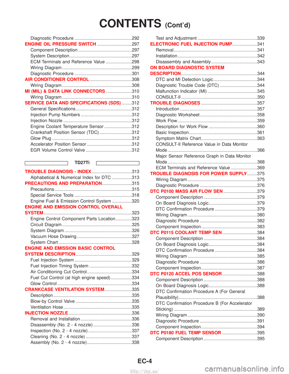
Diagnostic Procedure ..............................................292
ENGINE OIL PRESSURE SWITCH ............................297
Component Description ...........................................297
System Description ..................................................297
ECM Terminals and Reference Value .....................298
Wiring Diagram ........................................................299
Diagnostic Procedure ..............................................301
AIR CONDITIONER CONTROL ..................................308
Wiring Diagram ........................................................308
MI (MIL) & DATA LINK CONNECTORS .....................310
Wiring Diagram ........................................................310
SERVICE DATA AND SPECIFICATIONS (SDS) ........312
General Specifications .............................................312
Injection Pump Numbers .........................................312
Injection Nozzle .......................................................312
Engine Coolant Temperature Sensor ......................312
Crankshaft Position Sensor (TDC) ..........................312
Glow Plug ................................................................312
Accelerator Position Sensor ....................................312
EGR Volume Control Valve .....................................312
TD27Ti
TROUBLE DIAGNOSIS - INDEX ................................313
Alphabetical & Numerical Index for DTC ................313
PRECAUTIONS AND PREPARATION ........................315
Precautions ..............................................................315
Special Service Tools ..............................................318
Engine Fuel & Emission Control System ................320
ENGINE AND EMISSION CONTROL OVERALL
SYSTEM .......................................................................323
Engine Control Component Parts Location .............323
Circuit Diagram ........................................................325
System Diagram ......................................................326
Vacuum Hose Drawing ............................................327
System Chart ...........................................................328
ENGINE AND EMISSION BASIC CONTROL
SYSTEM DESCRIPTION .............................................329
Fuel Injection System ..............................................329
Fuel Injection Timing System ..................................332
Air Conditioning Cut Control ....................................334
Fuel Cut Control (at high engine speed) .................334
Glow Control ............................................................334
CRANKCASE VENTILATION SYSTEM ......................335
Description ...............................................................335
Blow-by Control Valve .............................................335
Ventilation Hose .......................................................335
INJECTION NOZZLE ...................................................336
Removal and Installation .........................................336
Disassembly (No.2-4 nozzle) ...............................336
Inspection (No.2-4 nozzle) ...................................337
Cleaning (No.2-4 nozzle) .....................................337
Assembly (No.2-4 nozzle) ....................................338 Test and Adjustment ................................................339
ELECTRONIC FUEL INJECTION PUMP ....................341
Removal ...................................................................341
Installation ................................................................342
Disassembly and Assembly .....................................343
ON BOARD DIAGNOSTIC SYSTEM
DESCRIPTION .............................................................344
DTC and MI Detection Logic ...................................344
Diagnostic Trouble Code (DTC) ..............................344
Malfunction Indicator (MI) ........................................345
CONSULT-II .............................................................350
TROUBLE DIAGNOSES .............................................357
Introduction ..............................................................357
Diagnostic Worksheet ..............................................358
Work Flow ................................................................359
Description for Work Flow .......................................360
Basic Inspection.......................................................361
Symptom Matrix Chart .............................................363
CONSULT-II Reference Value in Data Monitor
Mode ........................................................................\
366
Major Sensor Reference Graph in Data Monitor
Mode ........................................................................\
368
ECM Terminals and Reference Value .....................369
TROUBLE DIAGNOSIS FOR POWER SUPPLY ........375
Wiring Diagram ........................................................375
Diagnostic Procedure ..............................................376
DTC P0100 MASS AIR FLOW SEN ...........................379
Component Description ...........................................379
On Board Diagnosis Logic.......................................379
DTC Confirmation Procedure ..................................379
Wiring Diagram ........................................................380
Diagnostic Procedure ..............................................382
Component Inspection .............................................383
DTC P0115 COOLANT TEMP SEN ............................384
Component Description ...........................................384
On Board Diagnosis Logic.......................................384
DTC Confirmation Procedure ..................................384
Wiring Diagram ........................................................385
Diagnostic Procedure ..............................................386
Component Inspection .............................................387
DTC P0120 ACCEL POS SENSOR ............................388
Component Description ...........................................388
On Board Diagnosis Logic.......................................388
DTC Confirmation Procedure A (For General
Plausibility) ...............................................................388
DTC Confirmation Procedure B (For Accelerator
Sticking) ...................................................................389
Wiring Diagram ........................................................390
Diagnostic Procedure ..............................................391
Component Inspection .............................................394
DTC P0180 FUEL TEMP SENSOR ............................395
Component Description ...........................................395
CONTENTS(Cont'd)
EC-4
http://vnx.su/
Page 282 of 1833
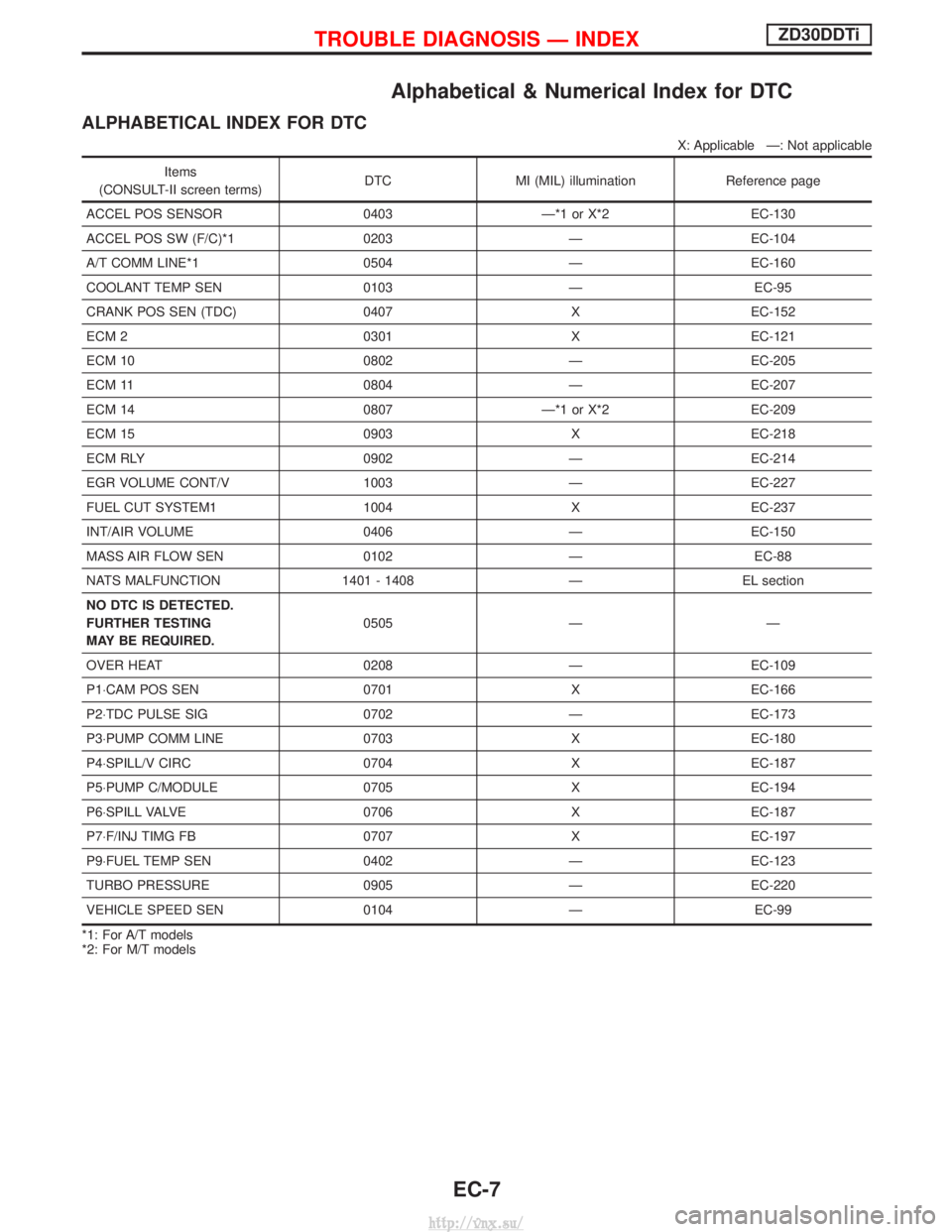
Alphabetical & Numerical Index for DTC
ALPHABETICAL INDEX FOR DTC
X: Applicable Ð: Not applicable
Items
(CONSULT-II screen terms) DTC MI (MIL) illumination Reference page
ACCEL POS SENSOR 0403 Ð*1 or X*2 EC-130
ACCEL POS SW (F/C)*1 0203 Ð EC-104
A/T COMM LINE*1 0504 Ð EC-160
COOLANT TEMP SEN 0103 Ð EC-95
CRANK POS SEN (TDC) 0407 X EC-152
ECM 2 0301 X EC-121
ECM 10 0802 Ð EC-205
ECM 11 0804 Ð EC-207
ECM 14 0807 Ð*1 or X*2 EC-209
ECM 15 0903 X EC-218
ECM RLY 0902 Ð EC-214
EGR VOLUME CONT/V 1003 Ð EC-227
FUEL CUT SYSTEM1 1004 X EC-237
INT/AIR VOLUME 0406 Ð EC-150
MASS AIR FLOW SEN 0102 Ð EC-88
NATS MALFUNCTION 1401 - 1408 Ð EL section
NO DTC IS DETECTED.
FURTHER TESTING
MAY BE REQUIRED. 0505 Ð Ð
OVER HEAT 0208 Ð EC-109
P1×CAM POS SEN 0701XEC-166
P2×TDC PULSE SIG 0702ÐEC-173
P3×PUMP COMM LINE 0703XEC-180
P4×SPILL/V CIRC 0704XEC-187
P5×PUMP C/MODULE 0705XEC-194
P6×SPILL VALVE 0706XEC-187
P7×F/INJ TIMG FB 0707XEC-197
P9×FUEL TEMP SEN 0402ÐEC-123
TURBO PRESSURE 0905ÐEC-220
VEHICLE SPEED SEN 0104ÐEC-99
*1: For A/T models
*2: For M/T models
TROUBLE DIAGNOSIS Ð INDEXZD30DDTi
EC-7
http://vnx.su/