oil pressure NISSAN TERRANO 2004 Service Repair Manual
[x] Cancel search | Manufacturer: NISSAN, Model Year: 2004, Model line: TERRANO, Model: NISSAN TERRANO 2004Pages: 1833, PDF Size: 53.42 MB
Page 8 of 1833
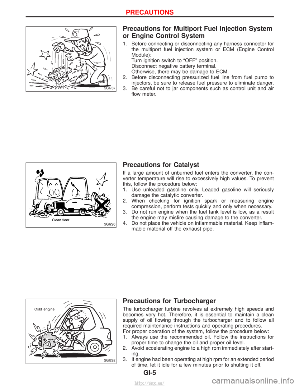
Precautions for Multiport Fuel Injection System
or Engine Control System
1. Before connecting or disconnecting any harness connector forthe multiport fuel injection system or ECM (Engine Control
Module):
Turn ignition switch to ªOFFº position.
Disconnect negative battery terminal.
Otherwise, there may be damage to ECM.
2. Before disconnecting pressurized fuel line from fuel pump to injectors, be sure to release fuel pressure to eliminate danger.
3. Be careful not to jar components such as control unit and air flow meter.
Precautions for Catalyst
If a large amount of unburned fuel enters the converter, the con-
verter temperature will rise to excessively high values. To prevent
this, follow the procedure below:
1. Use unleaded gasoline only. Leaded gasoline will seriouslydamage the catalytic converter.
2. When checking for ignition spark or measuring engine compression, perform tests quickly and only when necessary.
3. Do not run engine when the fuel tank level is low, as a result the engine may misfire causing damage to the converter.
4. Do not place the vehicle on inflammable material. Keep inflam- mable material off the exhaust pipe.
Precautions for Turbocharger
The turbocharger turbine revolves at extremely high speeds and
becomes very hot. Therefore, it is essential to maintain a clean
supply of oil flowing through the turbocharger and to follow all
required maintenance instructions and operating procedures.
For proper operation of the system, follow the procedure below:
1. Always use the recommended oil. Follow the instructions forproper time to change the oil and proper oil level.
2. Avoid accelerating engine to a high rpm immediately after start- ing.
3. If engine had been operating at high rpm for an extended period of time, let it idle for a few minutes prior to shutting it off.
SGI787
SGI290
SGI292
PRECAUTIONS
GI-5
http://vnx.su/
Page 44 of 1833
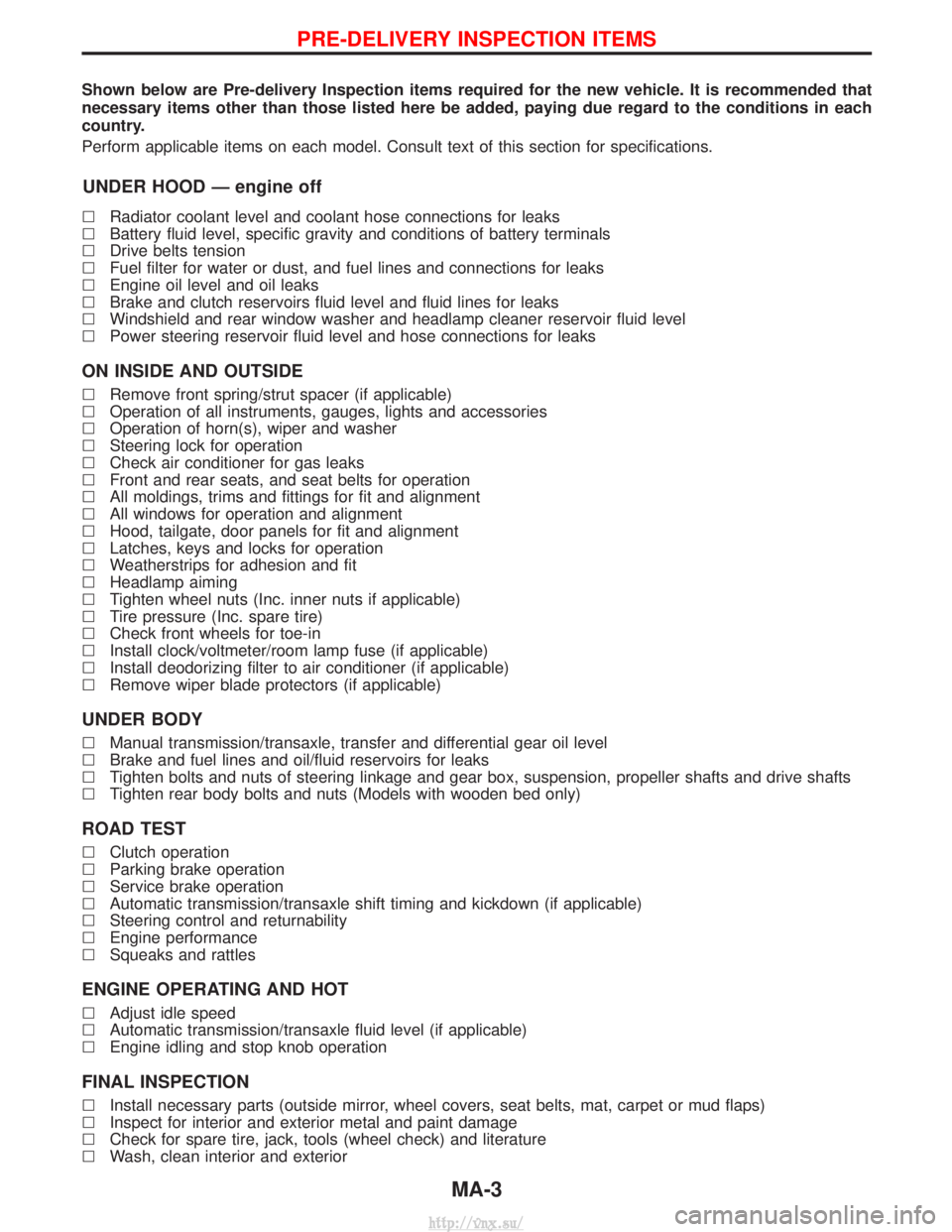
Shown below are Pre-delivery Inspection items required for the new vehicle. It is recommended that
necessary items other than those listed here be added, paying due regard to the conditions in each
country.
Perform applicable items on each model. Consult text of this section for specifications.
UNDER HOOD Ð engine off
lRadiator coolant level and coolant hose connections for leaks
l Battery fluid level, specific gravity and conditions of battery terminals
l Drive belts tension
l Fuel filter for water or dust, and fuel lines and connections for leaks
l Engine oil level and oil leaks
l Brake and clutch reservoirs fluid level and fluid lines for leaks
l Windshield and rear window washer and headlamp cleaner reservoir fluid level
l Power steering reservoir fluid level and hose connections for leaks
ON INSIDE AND OUTSIDE
lRemove front spring/strut spacer (if applicable)
l Operation of all instruments, gauges, lights and accessories
l Operation of horn(s), wiper and washer
l Steering lock for operation
l Check air conditioner for gas leaks
l Front and rear seats, and seat belts for operation
l All moldings, trims and fittings for fit and alignment
l All windows for operation and alignment
l Hood, tailgate, door panels for fit and alignment
l Latches, keys and locks for operation
l Weatherstrips for adhesion and fit
l Headlamp aiming
l Tighten wheel nuts (Inc. inner nuts if applicable)
l Tire pressure (Inc. spare tire)
l Check front wheels for toe-in
l Install clock/voltmeter/room lamp fuse (if applicable)
l Install deodorizing filter to air conditioner (if applicable)
l Remove wiper blade protectors (if applicable)
UNDER BODY
lManual transmission/transaxle, transfer and differential gear oil level
l Brake and fuel lines and oil/fluid reservoirs for leaks
l Tighten bolts and nuts of steering linkage and gear box, suspension, propeller shafts and drive shafts
l Tighten rear body bolts and nuts (Models with wooden bed only)
ROAD TEST
lClutch operation
l Parking brake operation
l Service brake operation
l Automatic transmission/transaxle shift timing and kickdown (if applicable)
l Steering control and returnability
l Engine performance
l Squeaks and rattles
ENGINE OPERATING AND HOT
lAdjust idle speed
l Automatic transmission/transaxle fluid level (if applicable)
l Engine idling and stop knob operation
FINAL INSPECTION
lInstall necessary parts (outside mirror, wheel covers, seat belts, mat, carpet or mud flaps)
l Inspect for interior and exterior metal and paint damage
l Check for spare tire, jack, tools (wheel check) and literature
l Wash, clean interior and exterior
PRE-DELIVERY INSPECTION ITEMS
MA-3
http://vnx.su/
Page 45 of 1833
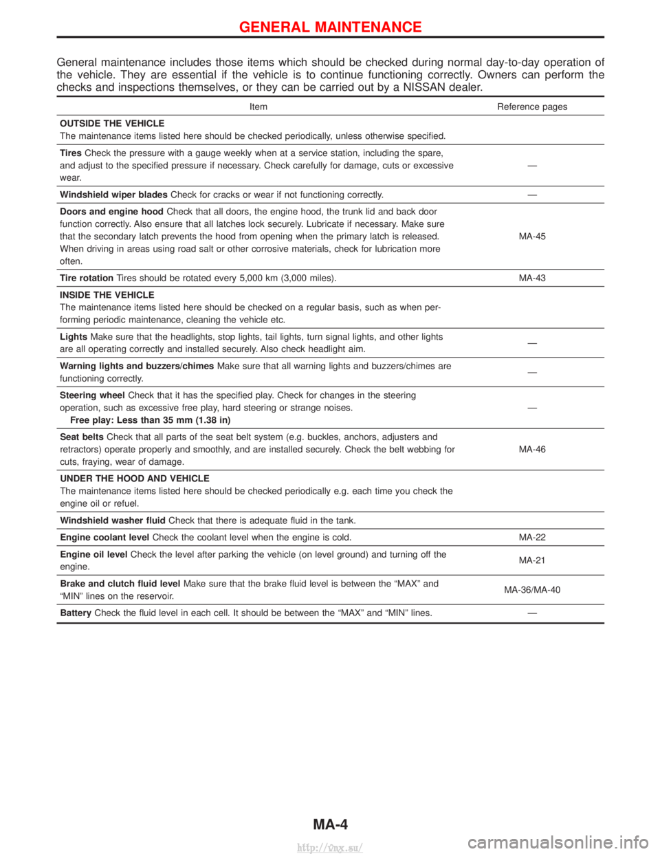
General maintenance includes those items which should be checked during normal day-to-day operation of
the vehicle. They are essential if the vehicle is to continue functioning correctly. Owners can perform the
checks and inspections themselves, or they can be carried out by a NISSAN dealer.
ItemReference pages
OUTSIDE THE VEHICLE
The maintenance items listed here should be checked periodically, unless otherwise specified.
Tires Check the pressure with a gauge weekly when at a service station, including the spare,
and adjust to the specified pressure if necessary. Check carefully for damage, cuts or excessive
wear. Ð
Windshield wiper blades Check for cracks or wear if not functioning correctly. Ð
Doors and engine hood Check that all doors, the engine hood, the trunk lid and back door
function correctly. Also ensure that all latches lock securely. Lubricate if necessary. Make sure
that the secondary latch prevents the hood from opening when the primary latch is released.
When driving in areas using road salt or other corrosive materials, check for lubrication more
often. MA-45
Tire rotation Tires should be rotated every 5,000 km (3,000 miles). MA-43
INSIDE THE VEHICLE
The maintenance items listed here should be checked on a regular basis, such as when per-
forming periodic maintenance, cleaning the vehicle etc.
Lights Make sure that the headlights, stop lights, tail lights, turn signal lights, and other lights
are all operating correctly and installed securely. Also check headlight aim. Ð
Warning lights and buzzers/chimes Make sure that all warning lights and buzzers/chimes are
functioning correctly. Ð
Steering wheel Check that it has the specified play. Check for changes in the steering
operation, such as excessive free play, hard steering or strange noises. Free play: Less than 35 mm (1.38 in) Ð
Seat belts Check that all parts of the seat belt system (e.g. buckles, anchors, adjusters and
retractors) operate properly and smoothly, and are installed securely. Check the belt webbing for
cuts, fraying, wear of damage. MA-46
UNDER THE HOOD AND VEHICLE
The maintenance items listed here should be checked periodically e.g. each time you check the
engine oil or refuel.
Windshield washer fluid Check that there is adequate fluid in the tank.
Engine coolant level Check the coolant level when the engine is cold. MA-22
Engine oil level Check the level after parking the vehicle (on level ground) and turning off the
engine. MA-21
Brake and clutch fluid level Make sure that the brake fluid level is between the ªMAXº and
ªMINº lines on the reservoir. MA-36/MA-40
Battery Check the fluid level in each cell. It should be between the ªMAXº and ªMINº lines. Ð
GENERAL MAINTENANCE
MA-4
http://vnx.su/
Page 46 of 1833
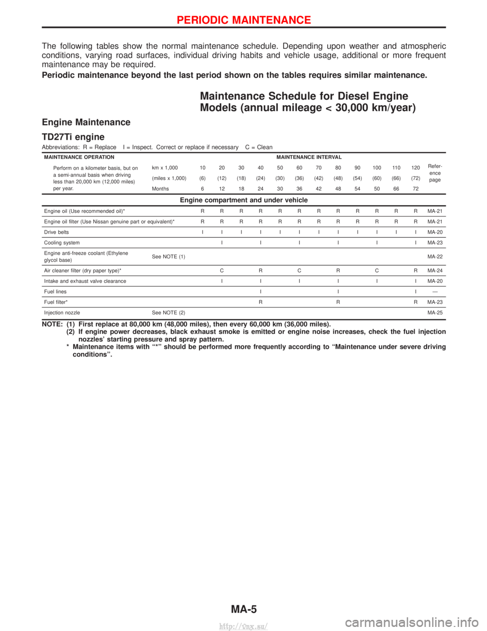
The following tables show the normal maintenance schedule. Depending upon weather and atmospheric
conditions, varying road surfaces, individual driving habits and vehicle usage, additional or more frequent
maintenance may be required.
Periodic maintenance beyond the last period shown on the tables requires similar maintenance.
Maintenance Schedule for Diesel Engine
Models (annual mileage < 30,000 km/year)
Engine Maintenance
TD27Ti engine
Abbreviations: R = Replace I = Inspect. Correct or replace if necessary C = Clean
MAINTENANCE OPERATIONMAINTENANCE INTERVAL
Refer-ence
page
Perform on a kilometer basis, but on
a semi-annual basis when driving
less than 20,000 km (12,000 miles)
per year. km x 1,000 10 20 30 40 50 60 70 80 90 100 110 120
(miles x 1,000) (6) (12) (18) (24) (30) (36) (42) (48) (54) (60) (66) (72)
Months 6 12 18 24 30 36 42 48 54 50 66 72
Engine compartment and under vehicle
Engine oil (Use recommended oil)*
RRRRRRRRRRRR MA-21
Engine oil filter (Use Nissan genuine part or equivalent)* RRRRRRRRRRRR MA-21
Drive belts IIIIIIIIIIII MA-20
Cooling system IIIIII MA-23
Engine anti-freeze coolant (Ethylene
glycol base) See NOTE (1)
MA-22
Air cleaner filter (dry paper type)* CRCRCR MA-24
Intake and exhaust valve clearance IIIIII MA-20
Fuel lines IIIÐ
Fuel filter* R R R MA-23
Injection nozzle See NOTE (2) MA-25
NOTE: (1) First replace at 80,000 km (48,000 miles), then every 60,000 km (36,000 miles).
(2) If engine power decreases, black exhaust smoke is emitted or engine noise increases, check the fuel injectionnozzles' starting pressure and spray pattern.
* Maintenance items with ª*º should be performed more frequently according to ªMaintenance under severe driving conditionsº.
PERIODIC MAINTENANCE
MA-5
http://vnx.su/
Page 49 of 1833
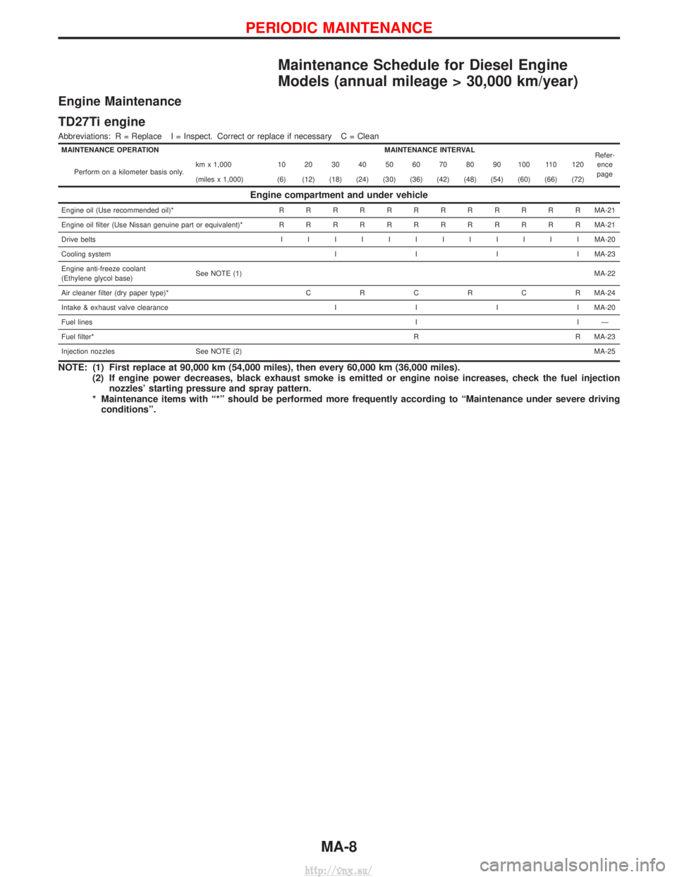
Maintenance Schedule for Diesel Engine
Models (annual mileage > 30,000 km/year)
Engine Maintenance
TD27Ti engine
Abbreviations: R = Replace I = Inspect. Correct or replace if necessary C = Clean
MAINTENANCE OPERATIONMAINTENANCE INTERVAL
Refer-
ence
page
Perform on a kilometer basis only. km x 1,000 10 20 30 40 50 60 70 80 90 100 110 120
(miles x 1,000) (6) (12) (18) (24) (30) (36) (42) (48) (54) (60) (66) (72)
Engine compartment and under vehicle
Engine oil (Use recommended oil)*
RRRRRRRRRRRR MA-21
Engine oil filter (Use Nissan genuine part or equivalent)* RRRRRRRRRRRR MA-21
Drive belts IIIIIIIIIIII MA-20
Cooling system IIIIMA-23
Engine anti-freeze coolant
(Ethylene glycol base) See NOTE (1)
MA-22
Air cleaner filter (dry paper type)* CRCRCR MA-24
Intake & exhaust valve clearance IIIIMA-20
Fuel lines IIÐ
Fuel filter* R R MA-23
Injection nozzles See NOTE (2) MA-25
NOTE: (1) First replace at 90,000 km (54,000 miles), then every 60,000 km (36,000 miles).
(2) If engine power decreases, black exhaust smoke is emitted or engine noise increases, check the fuel injectionnozzles' starting pressure and spray pattern.
* Maintenance items with ª*º should be performed more frequently according to ªMaintenance under severe driving conditionsº.
PERIODIC MAINTENANCE
MA-8
http://vnx.su/
Page 89 of 1833
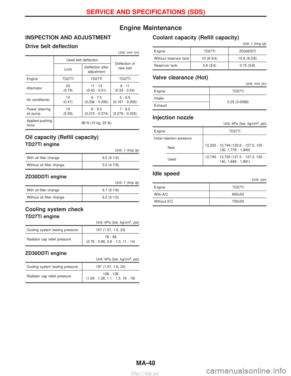
Engine Maintenance
INSPECTION AND ADJUSTMENT
Drive belt deflection
Unit: mm (in)
Used belt deflectionDeflection of
new belt
Limit Deflection after
adjustment
Engine TD27Ti TD27Ti TD27Ti
Alternator 20
(0.79) 11-13
(0.43 - 0.51) 9-11
(0.35 - 0.43)
Air conditioner 12
(0.47) 6 - 7.5
(0.236 - 0.295) 5 - 6.5
(0.197 - 0.256)
Power steering
oil pump 15
(0.59) 8 - 9.5
(0.315 - 0.374) 7 - 8.5
(0.276 - 0.335)
Applied pushing
force 98 N (10 kg, 22 lb)
Oil capacity (Refill capacity)
TD27Ti engine
Unit:
(Imp qt)
With oil filter change 6.2 (5-1/2)
Without oil filter change 5.5 (4-7/8)
ZD30DDTi engine
Unit: (Imp qt)
With oil filter change 6.7 (5-7/8)
Without oil filter change 6.2 (5-1/2)
Cooling system check
TD27Ti engine
Unit: kPa (bar, kg/cm2, psi)
Cooling system testing pressure 157 (1.57, 1.6, 23)
Radiator cap relief pressure 78-98
(0.78 - 0.98, 0.8 - 1.0, 11 - 14)
ZD30DDTi engine
Unit: kPa (bar, kg/cm2, psi)
Cooling system testing pressure 157 (1.57, 1.6, 23)
Radiator cap relief pressure 108 - 128
(1.08 - 1.28, 1.1 - 1.3, 16 - 18)
Coolant capacity (Refill capacity)
Unit: (Imp qt)
Engine TD27TiZD30DDTi
Without reservoir tank 10 (8-3/4) 10.6 (9-3/8)
Reservoir tank 0.8 (3/4) 0.75 (5/8)
Valve clearance (Hot)
Unit: mm (in)
Engine TD27Ti
Intake 0.25 (0.0098)
Exhaust
Injection nozzle
Unit: kPa (bar, kg/cm2, psi)
Engine TD27Ti
Initial injection pressure
New 12,259 - 12,749 (122.6 - 127.5, 125 -
130, 1,778 - 1,849)
Used 12,749 - 13,730 (127.5 - 137.3, 130 -
140, 1,849 - 1,991)
Idle speed
Unit: rpm
Engine TD27Ti
With A/C 850 50
Without A/C 700 50
SERVICE AND SPECIFICATIONS (SDS)
MA-48
http://vnx.su/
Page 92 of 1833
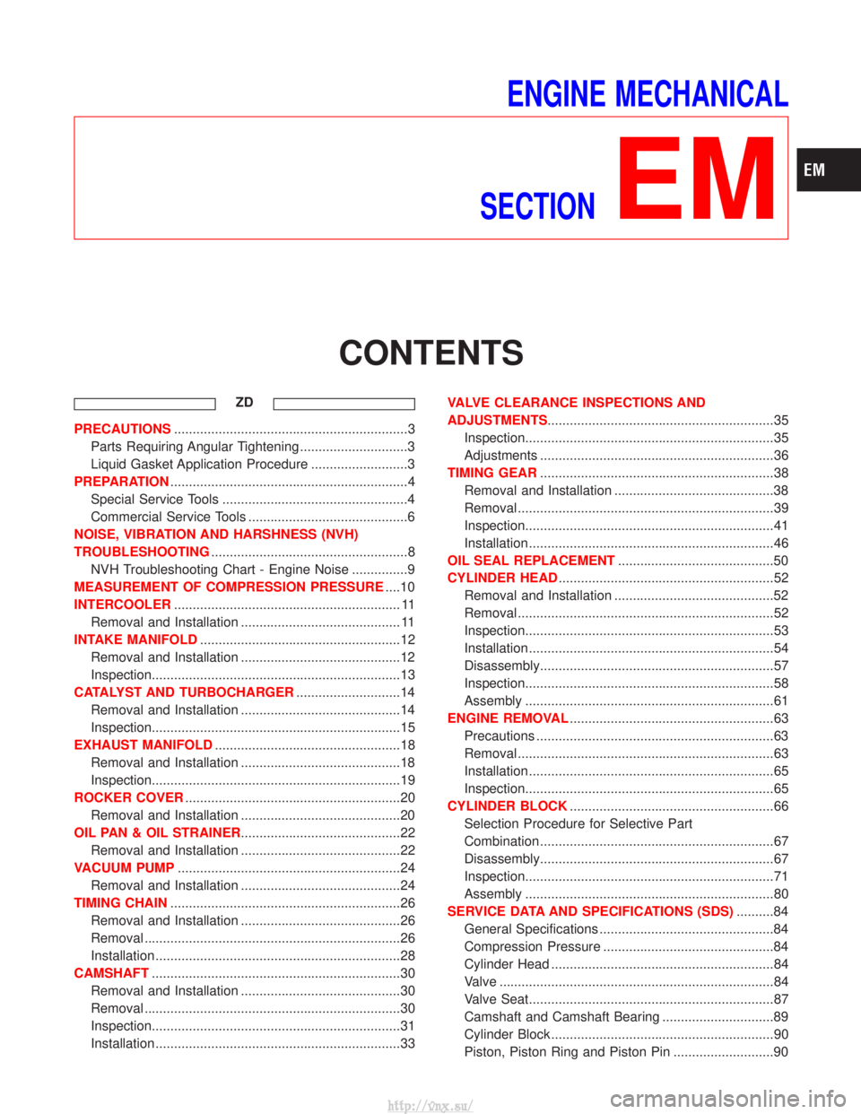
ENGINE MECHANICAL
SECTION
EM
CONTENTS
ZD
PRECAUTIONS ...............................................................3
Parts Requiring Angular Tightening .............................3
Liquid Gasket Application Procedure ..........................3
PREPARATION ................................................................4
Special Service Tools ..................................................4
Commercial Service Tools ...........................................6
NOISE, VIBRATION AND HARSHNESS (NVH)
TROUBLESHOOTING .....................................................8
NVH Troubleshooting Chart - Engine Noise ...............9
MEASUREMENT OF COMPRESSION PRESSURE ....10
INTERCOOLER ............................................................. 11
Removal and Installation ........................................... 11
INTAKE MANIFOLD ......................................................12
Removal and Installation ...........................................12
Inspection...................................................................13
CATALYST AND TURBOCHARGER ............................14
Removal and Installation ...........................................14
Inspection...................................................................15
EXHAUST MANIFOLD ..................................................18
Removal and Installation ...........................................18
Inspection...................................................................19
ROCKER COVER ..........................................................20
Removal and Installation ...........................................20
OIL PAN & OIL STRAINER ...........................................22
Removal and Installation ...........................................22
VACUUM PUMP ............................................................24
Removal and Installation ...........................................24
TIMING CHAIN ..............................................................26
Removal and Installation ...........................................26
Removal .....................................................................26
Installation ..................................................................28
CAMSHAFT ...................................................................30
Removal and Installation ...........................................30
Removal .....................................................................30
Inspection...................................................................31
Installation ..................................................................33 VALVE CLEARANCE INSPECTIONS AND
ADJUSTMENTS
.............................................................35
Inspection...................................................................35
Adjustments ...............................................................36
TIMING GEAR ...............................................................38
Removal and Installation ...........................................38
Removal .....................................................................39
Inspection...................................................................41
Installation ..................................................................46
OIL SEAL REPLACEMENT ..........................................50
CYLINDER HEAD ..........................................................52
Removal and Installation ...........................................52
Removal .....................................................................52
Inspection...................................................................53
Installation ..................................................................54
Disassembly...............................................................57
Inspection...................................................................58
Assembly ...................................................................61
ENGINE REMOVAL .......................................................63
Precautions ................................................................63
Removal .....................................................................63
Installation ..................................................................65
Inspection...................................................................65
CYLINDER BLOCK .......................................................66
Selection Procedure for Selective Part
Combination ...............................................................67
Disassembly...............................................................67
Inspection...................................................................71
Assembly ...................................................................80
SERVICE DATA AND SPECIFICATIONS (SDS) ..........84
General Specifications ...............................................84
Compression Pressure ..............................................84
Cylinder Head ............................................................84
Valve ........................................................................\
..84
Valve Seat..................................................................87
Camshaft and Camshaft Bearing ..............................89
Cylinder Block ............................................................90
Piston, Piston Ring and Piston Pin ...........................90
http://vnx.su/
Page 93 of 1833
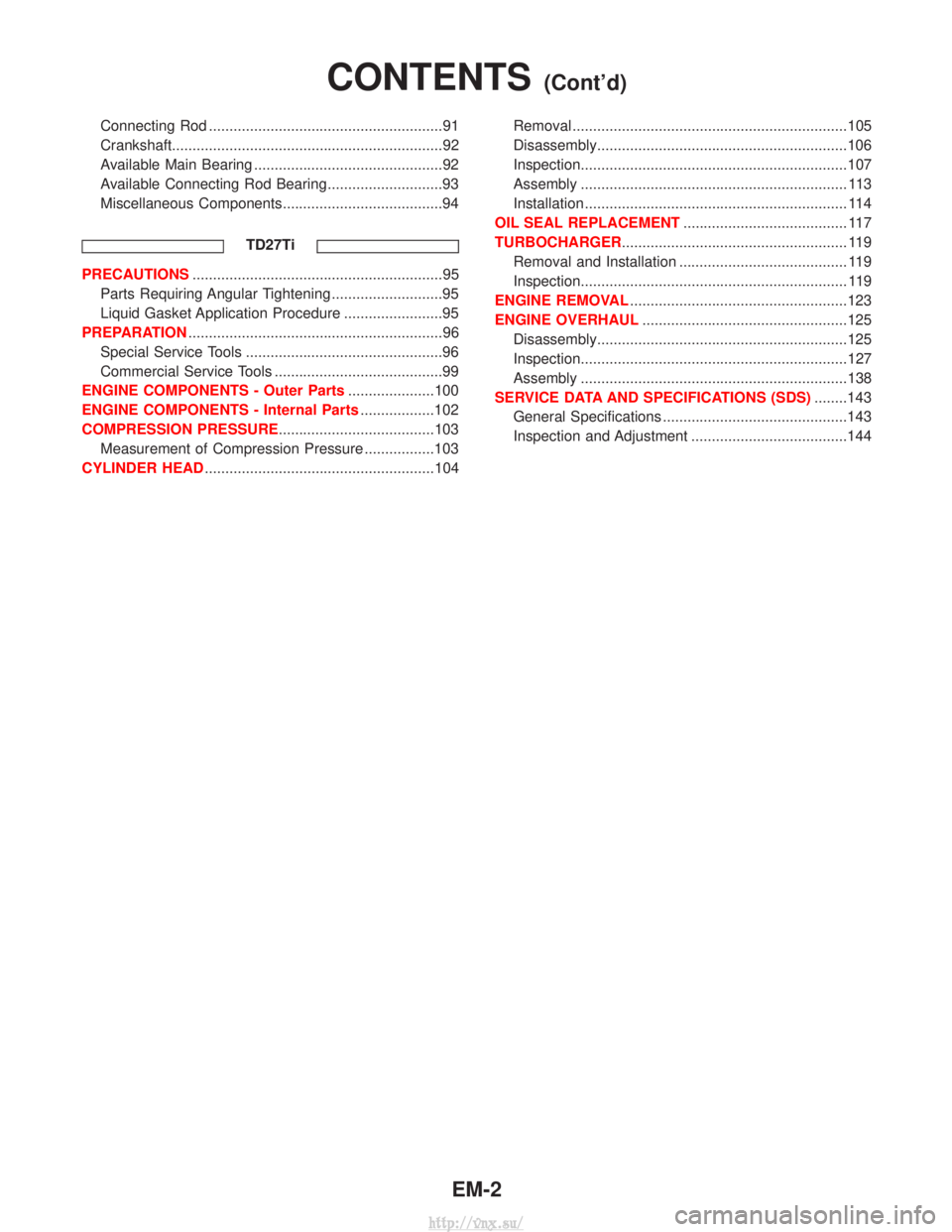
Connecting Rod .........................................................91
Crankshaft..................................................................92
Available Main Bearing ..............................................92
Available Connecting Rod Bearing............................93
Miscellaneous Components.......................................94TD27Ti
PRECAUTIONS.............................................................95
Parts Requiring Angular Tightening ...........................95
Liquid Gasket Application Procedure ........................95
PREPARATION ..............................................................96
Special Service Tools ................................................96
Commercial Service Tools .........................................99
ENGINE COMPONENTS - Outer Parts .....................100
ENGINE COMPONENTS - Internal Parts ..................102
COMPRESSION PRESSURE......................................103 Measurement of Compression Pressure .................103
CYLINDER HEAD ........................................................104 Removal ...................................................................105
Disassembly.............................................................106
Inspection.................................................................107
Assembly ................................................................. 113
Installation ................................................................ 114
OIL SEAL REPLACEMENT ........................................ 117
TURBOCHARGER ....................................................... 119
Removal and Installation ......................................... 119
Inspection................................................................. 119
ENGINE REMOVAL .....................................................123
ENGINE OVERHAUL ..................................................125
Disassembly.............................................................125
Inspection.................................................................127
Assembly .................................................................138
SERVICE DATA AND SPECIFICATIONS (SDS) ........143
General Specifications .............................................143
Inspection and Adjustment ......................................144
CONTENTS(Cont'd)
EM-2
http://vnx.su/
Page 96 of 1833
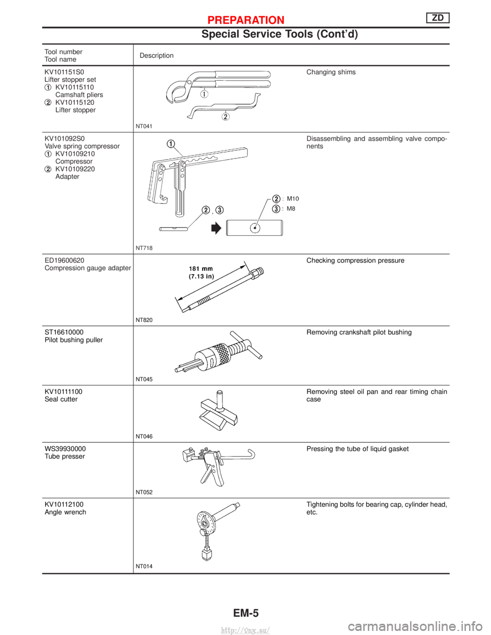
Tool number
Tool nameDescription
KV101151S0
Lifter stopper set
q
1KV10115110
Camshaft pliers
q
2KV10115120
Lifter stopper
NT041
Changing shims
KV101092S0
Valve spring compressor
q
1KV10109210
Compressor
q
2KV10109220
Adapter
NT718
Disassembling and assembling valve compo-
nents
ED19600620
Compression gauge adapter
NT820
Checking compression pressure
ST16610000
Pilot bushing puller
NT045
Removing crankshaft pilot bushing
KV101111 0 0
Seal cutter
NT046
Removing steel oil pan and rear timing chain
case
WS39930000
Tube presser
NT052
Pressing the tube of liquid gasket
KV10112100
Angle wrench
NT014
Tightening bolts for bearing cap, cylinder head,
etc.
PREPARATIONZD
Special Service Tools (Cont'd)
EM-5
http://vnx.su/
Page 101 of 1833
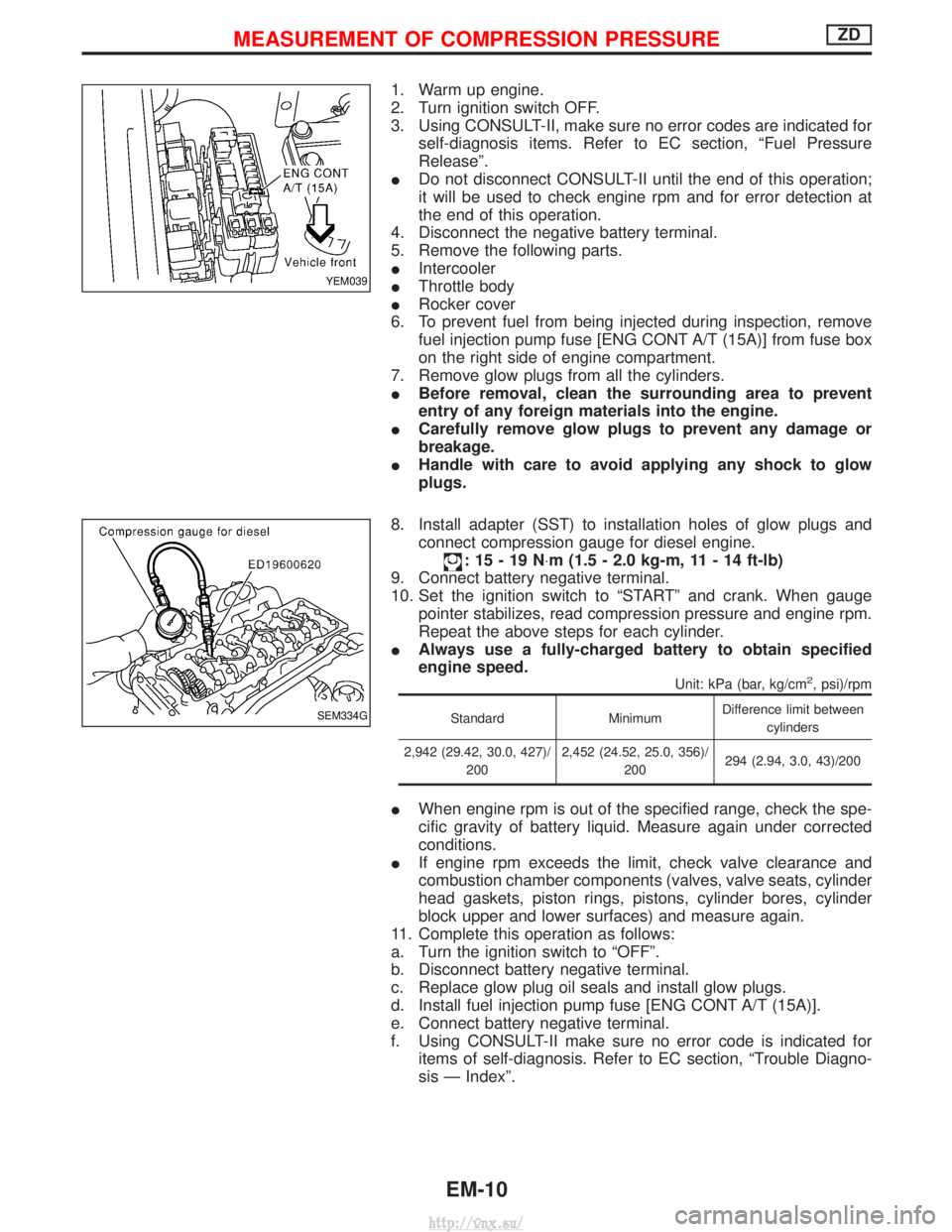
1. Warm up engine.
2. Turn ignition switch OFF.
3. Using CONSULT-II, make sure no error codes are indicated forself-diagnosis items. Refer to EC section, ªFuel Pressure
Releaseº.
I Do not disconnect CONSULT-II until the end of this operation;
it will be used to check engine rpm and for error detection at
the end of this operation.
4. Disconnect the negative battery terminal.
5. Remove the following parts.
I Intercooler
I Throttle body
I Rocker cover
6. To prevent fuel from being injected during inspection, remove fuel injection pump fuse [ENG CONT A/T (15A)] from fuse box
on the right side of engine compartment.
7. Remove glow plugs from all the cylinders.
I Before removal, clean the surrounding area to prevent
entry of any foreign materials into the engine.
I Carefully remove glow plugs to prevent any damage or
breakage.
I Handle with care to avoid applying any shock to glow
plugs.
8. Install adapter (SST) to installation holes of glow plugs and connect compression gauge for diesel engine.
:15-19N ×m (1.5 - 2.0 kg-m, 11 - 14 ft-lb)
9. Connect battery negative terminal.
10. Set the ignition switch to ªSTARTº and crank. When gauge pointer stabilizes, read compression pressure and engine rpm.
Repeat the above steps for each cylinder.
I Always use a fully-charged battery to obtain specified
engine speed.
Unit: kPa (bar, kg/cm2, psi)/rpm
Standard MinimumDifference limit between
cylinders
2,942 (29.42, 30.0, 427)/ 200 2,452 (24.52, 25.0, 356)/
200 294 (2.94, 3.0, 43)/200
I
When engine rpm is out of the specified range, check the spe-
cific gravity of battery liquid. Measure again under corrected
conditions.
I If engine rpm exceeds the limit, check valve clearance and
combustion chamber components (valves, valve seats, cylinder
head gaskets, piston rings, pistons, cylinder bores, cylinder
block upper and lower surfaces) and measure again.
11. Complete this operation as follows:
a. Turn the ignition switch to ªOFFº.
b. Disconnect battery negative terminal.
c. Replace glow plug oil seals and install glow plugs.
d. Install fuel injection pump fuse [ENG CONT A/T (15A)].
e. Connect battery negative terminal.
f. Using CONSULT-II make sure no error code is indicated for items of self-diagnosis. Refer to EC section, ªTrouble Diagno-
sis Ð Indexº.
YEM039
SEM334G
MEASUREMENT OF COMPRESSION PRESSUREZD
EM-10
http://vnx.su/