service NISSAN TERRANO 2004 Service Repair Manual
[x] Cancel search | Manufacturer: NISSAN, Model Year: 2004, Model line: TERRANO, Model: NISSAN TERRANO 2004Pages: 1833, PDF Size: 53.42 MB
Page 1711 of 1833
Trouble Diagnosis
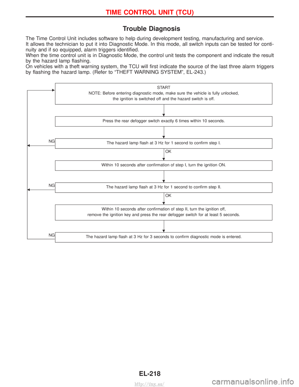
The Time Control Unit includes software to help during development testing, manufacturing and service.
It allows the technician to put it into Diagnostic Mode. In this mode, all switch inputs can be tested for conti-
nuity and if so equipped, alarm triggers identified.
When the time control unit is in Diagnostic Mode, the control unit tests the component and indicate the result
by the hazard lamp flashing.
On vehicles with a theft warning system, the TCU will first indicate the source of the last three alarm triggers
by flashing the hazard lamp. (Refer to ªTHEFT WARNING SYSTEMº, EL-243.)
ESTART
NOTE: Before entering diagnostic mode, make sure the vehicle is fully unlocked, the ignition is switched off and the hazard switch is off.
Press the rear defogger switch exactly 6 times within 10 seconds.
FNG The hazard lamp flash at 3 Hz for 1 second to confirm step I.
OK
Within 10 seconds after confirmation of step I, turn the ignition ON.
FNG The hazard lamp flash at 3 Hz for 1 second to confirm step II.
OK
Within 10 seconds after confirmation of step II, turn the ignition off,
remove the ignition key and press the rear defogger switch for at least 5 seconds.
NGThe hazard lamp flash at 3 Hz for 3 seconds to confirm diagnostic mode is entered.
H
H
H
H
H
H
TIME CONTROL UNIT (TCU)
EL-218
http://vnx.su/
Page 1722 of 1833
CONSULT-II
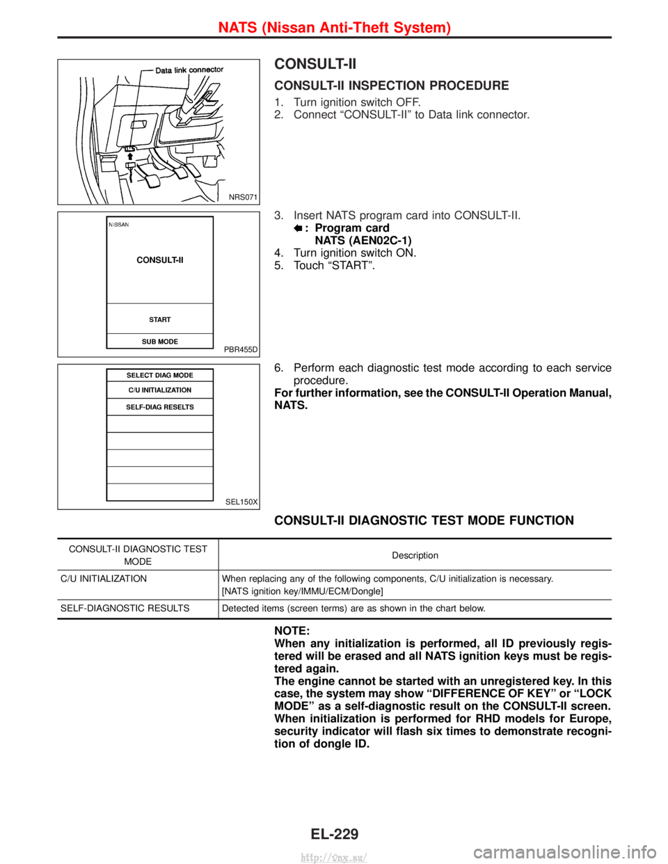
CONSULT-II INSPECTION PROCEDURE
1. Turn ignition switch OFF.
2. Connect ªCONSULT-IIº to Data link connector.
3. Insert NATS program card into CONSULT-II.
: Program cardNATS (AEN02C-1)
4. Turn ignition switch ON.
5. Touch ªSTARTº.
6. Perform each diagnostic test mode according to each service procedure.
For further information, see the CONSULT-II Operation Manual,
NATS.
CONSULT-II DIAGNOSTIC TEST MODE FUNCTION
CONSULT-II DIAGNOSTIC TEST
MODE Description
C/U INITIALIZATION When replacing any of the following components, C/U initialization is necessary. [NATS ignition key/IMMU/ECM/Dongle]
SELF-DIAGNOSTIC RESULTS Detected items (screen terms) are as shown in the chart below.
NOTE:
When any initialization is performed, all ID previously regis-
tered will be erased and all NATS ignition keys must be regis-
tered again.
The engine cannot be started with an unregistered key. In this
case, the system may show ªDIFFERENCE OF KEYº or ªLOCK
MODEº as a self-diagnostic result on the CONSULT-II screen.
When initialization is performed for RHD models for Europe,
security indicator will flash six times to demonstrate recogni-
tion of dongle ID.
NRS071
PBR455D
SEL150X
NATS (Nissan Anti-Theft System)
EL-229
http://vnx.su/
Page 1724 of 1833
Trouble Diagnoses
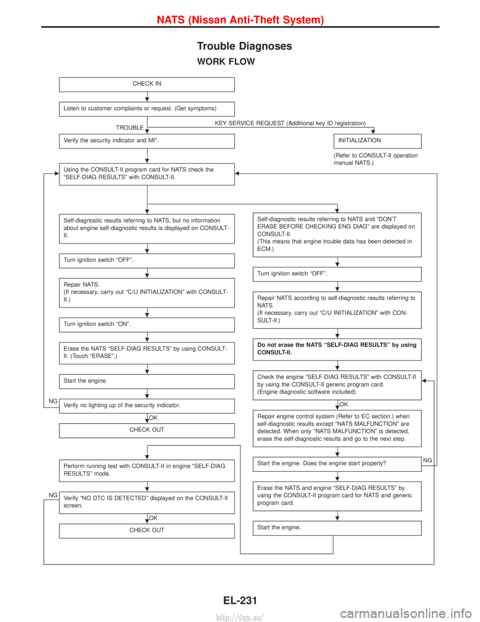
WORK FLOW
CHECK IN
Listen to customer complaints or request. (Get symptoms)
TROUBLEKEY SERVICE REQUEST (Additional key ID registration)H
Verify the security indicator and MI*.INITIALIZATION
(Refer to CONSULT-II operation
manual NATS.)
EUsing the CONSULT-II program card for NATS check the
ªSELF-DIAG RESULTSº with CONSULT-II.F
Self-diagnostic results referring to NATS, but no information
about engine self-diagnostic results is displayed on CONSULT-
II.
Turn ignition switch ªOFFº.
Repair NATS.
(If necessary, carry out ªC/U INITIALIZATIONº with CONSULT-
II.)
Turn ignition switch ªONº.
Erase the NATS ªSELF-DIAG RESULTSº by using CONSULT-
II. (Touch ªERASEº.)
Start the engine.
NGVerify no lighting up of the security indicator.
OK
CHECK OUT
Perform running test with CONSULT-II in engine ªSELF-DIAG
RESULTSº mode.
NGVerify ªNO DTC IS DETECTEDº displayed on the CONSULT-II
screen.
OK
CHECK OUT
Self-diagnostic results referring to NATS and ªDON'T
ERASE BEFORE CHECKING ENG DIAGº are displayed on
CONSULT-II.
(This means that engine trouble data has been detected in
ECM.)
Turn ignition switch ªOFFº.
Repair NATS according to self-diagnostic results referring to
NATS.
(If necessary, carry out ªC/U INITIALIZATIONº with CON-
SULT-II.)
Do not erase the NATS ªSELF-DIAG RESULTSº by using
CONSULT-II.
Check the engine ªSELF-DIAG RESULTSº with CONSULT-II
by using the CONSULT-II generic program card.
(Engine diagnostic software included)
OK
F
Repair engine control system (Refer to EC section.) when
self-diagnostic results except ªNATS MALFUNCTIONº are
detected. When only ªNATS MALFUNCTIONº is detected,
erase the self-diagnostic results and go to the next step.
Start the engine. Does the engine start properly?NG
Erase the NATS and engine ªSELF-DIAG RESULTSº by
using the CONSULT-II program card for NATS and generic
program card.
Start the engine.
H
H
H
HH
H
H
H
H
H
H
H
H
H
H
H
H
H
H
H
H
H
H
NATS (Nissan Anti-Theft System)
EL-231
http://vnx.su/
Page 1829 of 1833
F
Fan switch ......................................................HA-60
F/FOG - Wiring diagram .................................EL-55
Final drive disassembly............................PD-15, 37
Final drive pre-inspection .........................PD-15, 37
Final drive removal and installation ...............PD-15
Finisher, interior - See Trim ............................BT-18
Finisher, rear panel .........................................BT-18
Floor trim .........................................................BT-18
Fluid temperature sensor (A/T) .....................AT-146
Fluids .............................................MA-5, 17, 20, 36
Flywheel (clutch) .......................................CL-11, 12
Flywheel runout..............................................EM-94
Fog lamp, front .........................................EL-55, 57
Fog lamp, rear ................................................EL-58
Fork rod (M/T) ................................................MT-13
Forward clutch...............................................AT-162
Front axle ....................................................FA-4, 13
Front bumper ....................................................BT-6
Front case (Transfer) ..................................TF-9, 23
Front combination lamp removal andinstallation .....................................................BT-6
Front disc brake .............................................BR-27
Front door .......................................................BT-10
Front Door Trim...............................................BT-19
Front drive shaft (Transfer) .........................TF-9, 19
Front final drive disassembly (4WD) ..............PD-14
Front final drive removal and installa- tion (4WD) ............................................PD-12, 13
Front fog lamp ..........................................EL-55, 57
Front passenger air bag .................................RS-19
Front seat ........................................................BT-34
Front seat belt ..................................................RS-4
Front seat belt pre-tensioner ..........................RS-14
Front side air bag ...........................................RS-20
Front suspension ........................................FA-4, 29
Fuel cut control (at no load & high engine speed).....................................EC-22, 334
Fuel cut solenoid valve ................................EC-399
Fuel cut system ............................................EC-237
Fuel filler lid.......................................................BT-8
Fuel filter replacement...................MA-5, 20, 23, 33
Fuel gauge..................................FE-3, 6, EL-86, 98
Fuel injection system .............................EC-20, 329
Fuel injection timing feed back (Elec- tronic Fuel Injection Pump) ......................EC-197
Fuel precautions ................................................GI-6
Fuel pump and gauge ..............................FE-3, 6, 7
Fuel system ..................................................FE-3, 6
Fuel tank .......................................................FE-3, 6
Fuel temperature sensor ......................EC-123, 395
Fuse ................................................................EL-19
Fuse and fusible link box .............................Foldout
Fuse block ....................................................Foldout
Fusible link ......................................................EL-19 GGarage jack and safety stand .........................GI-31
Gauges .....................................................EL-82, 85
Gear components (M/T) ........MT-11, 14, 16, 21, 23
Generator - See Alternator .............................SC-27
GLOW - Wiring diagram...............................EC-246
Glow control system ....................EC-244, 334, 412
Glow plug .............................................EC-244, 413
Glow relay ............................................EC-246, 419
Grease .........................................MA-17, 39, 40, 44
Ground distribution..........................................EL-20
H
Harness connector ............................................EL-5
Harness connector inspection .........................GI-19
Harness layout ....EL-280, 281, 282, 298, 310, 312,320, 321, 322, 323, 324
Hazard warning lamp................................EL-61, 62
Headlamp ......EL-28, 32, 33, 34, 41, 42, 43, 46, 47
Headlamp aiming control .............EL-41, 42, 43, 46
Headlamp washer .........................................EL-118
Headlining - See Roof trim .............................BT-20
Heat up switch..............................................EC-265
Heated seat .......................................BT-36, EL-151
HEATER - Wiring diagram .............................HA-41
HEATUP - Wiring diagram ...........................EC-266
Height (Dimensions) ........................................GI-10
HFC134a (R134a) system precaution .............HA-3
HFC134a (R134a) system service procedure....................................................HA-15
HFC134a (R134a) system service tools ........HA-11
High clutch ....................................................AT-160
H/LAMP - Wiring diagram ............EL-28, 34, 43, 62
Hood..................................................................BT-6
Hood lock system .............................................BT-6
Horn ..............................................................EL-122
HORN - Wiring diagram................................EL-122
How to erase DTC for OBD system ......EC-33, 344
HSEAT - Wiring diagram...............................EL-151
I
Identification .....................................................HA-2
Identification plate .....................................GI-28, 29
Idle speed...............................................EC-50, 361
Idle speed inspection ...............................MA-20, 26
ILL - Wiring diagram .......................................EL-68
Illumination ................................................EL-67, 68
Injection nozzle ......................................EC-24, 336
Injection nozzle inspection ..................MA-5, 20, 25
Injection timing control valve ........................EC-403
INJPMP - Wiring diagram ...EC-126, 169, 176, 183, 190, 200, 240
Instrument panel .............................................BT-16
INT/L - Wiring diagram....................................EL-74
ALPHABETICAL INDEX
IDX-4
http://vnx.su/
Page 1831 of 1833
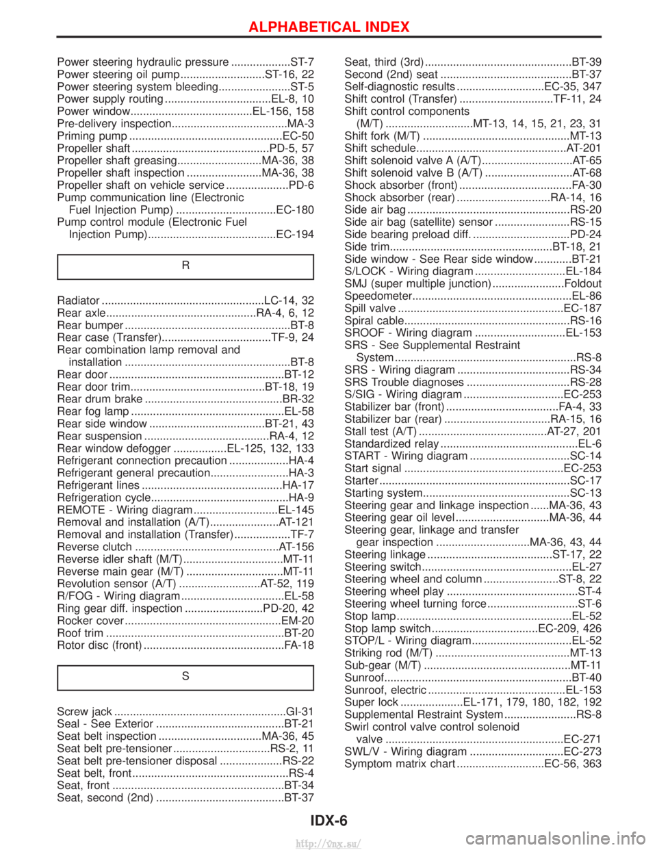
Power steering hydraulic pressure ...................ST-7
Power steering oil pump ...........................ST-16, 22
Power steering system bleeding.......................ST-5
Power supply routing ..................................EL-8, 10
Power window.......................................EL-156, 158
Pre-delivery inspection.....................................MA-3
Priming pump .................................................EC-50
Propeller shaft ............................................PD-5, 57
Propeller shaft greasing...........................MA-36, 38
Propeller shaft inspection ........................MA-36, 38
Propeller shaft on vehicle service ....................PD-6
Pump communication line (ElectronicFuel Injection Pump) ................................EC-180
Pump control module (Electronic Fuel Injection Pump).........................................EC-194
R
Radiator ....................................................LC-14, 32
Rear axle................................................RA-4, 6, 12
Rear bumper .....................................................BT-8
Rear case (Transfer)...................................TF-9, 24
Rear combination lamp removal andinstallation .....................................................BT-8
Rear door ........................................................BT-12
Rear door trim...........................................BT-18, 19
Rear drum brake ............................................BR-32
Rear fog lamp .................................................EL-58
Rear side window .....................................BT-21, 43
Rear suspension ........................................RA-4, 12
Rear window defogger .................EL-125, 132, 133
Refrigerant connection precaution ...................HA-4
Refrigerant general precaution.........................HA-3
Refrigerant lines .............................................HA-17
Refrigeration cycle............................................HA-9
REMOTE - Wiring diagram ...........................EL-145
Removal and installation (A/T)......................AT-121
Removal and installation (Transfer) ..................TF-7
Reverse clutch ..............................................AT-156
Reverse idler shaft (M/T)................................MT-11
Reverse main gear (M/T) ...............................MT-11
Revolution sensor (A/T) ..........................AT-52, 119
R/FOG - Wiring diagram .................................EL-58
Ring gear diff. inspection .........................PD-20, 42
Rocker cover ..................................................EM-20
Roof trim .........................................................BT-20
Rotor disc (front) .............................................FA-18
S
Screw jack .......................................................GI-31
Seal - See Exterior .........................................BT-21
Seat belt inspection .................................MA-36, 45
Seat belt pre-tensioner ...............................RS-2, 11
Seat belt pre-tensioner disposal ....................RS-22
Seat belt, front ..................................................RS-4
Seat, front .......................................................BT-34
Seat, second (2nd) .........................................BT-37 Seat, third (3rd) ...............................................BT-39
Second (2nd) seat ..........................................BT-37
Self-diagnostic results ............................EC-35, 347
Shift control (Transfer) ..............................TF-11, 24
Shift control components
(M/T) ............................MT-13, 14, 15, 21, 23, 31
Shift fork (M/T) ...............................................MT-13
Shift schedule................................................AT-201
Shift solenoid valve A (A/T).............................AT-65
Shift solenoid valve B (A/T) ............................AT-68
Shock absorber (front) ....................................FA-30
Shock absorber (rear) ..............................RA-14, 16
Side air bag ....................................................RS-20
Side air bag (satellite) sensor ........................RS-15
Side bearing preload diff. ...............................PD-24
Side trim....................................................BT-18, 21
Side window - See Rear side window ............BT-21
S/LOCK - Wiring diagram .............................EL-184
SMJ (super multiple junction) .......................Foldout
Speedometer...................................................EL-86
Spill valve .....................................................EC-187
Spiral cable.....................................................RS-16
SROOF - Wiring diagram .............................EL-153
SRS - See Supplemental Restraint System ..........................................................RS-8
SRS - Wiring diagram ....................................RS-34
SRS Trouble diagnoses .................................RS-28
S/SIG - Wiring diagram ................................EC-253
Stabilizer bar (front) ....................................FA-4, 33
Stabilizer bar (rear) ..................................RA-15, 16
Stall test (A/T) .........................................AT-27, 201
Standardized relay ............................................EL-6
START - Wiring diagram ................................SC-14
Start signal ...................................................EC-253
Starter .............................................................SC-17
Starting system...............................................SC-13
Steering gear and linkage inspection ......MA-36, 43
Steering gear oil level ..............................MA-36, 44
Steering gear, linkage and transfer gear inspection ..............................MA-36, 43, 44
Steering linkage ........................................ST-17, 22
Steering switch................................................EL-27
Steering wheel and column ........................ST-8, 22
Steering wheel play ..........................................ST-4
Steering wheel turning force .............................ST-6
Stop lamp ........................................................EL-52
Stop lamp switch ..................................EC-209, 426
STOP/L - Wiring diagram................................EL-52
Striking rod (M/T) ...........................................MT-13
Sub-gear (M/T) ...............................................MT-11
Sunroof............................................................BT-40
Sunroof, electric ............................................EL-153
Super lock ....................EL-171, 179, 180, 182, 192
Supplemental Restraint System .......................RS-8
Swirl control valve control solenoid valve .........................................................EC-271
SWL/V - Wiring diagram ..............................EC-273
Symptom matrix chart ............................EC-56, 363
ALPHABETICAL INDEX
IDX-6
http://vnx.su/