fuel pump NISSAN TERRANO 2004 Service Manual Online
[x] Cancel search | Manufacturer: NISSAN, Model Year: 2004, Model line: TERRANO, Model: NISSAN TERRANO 2004Pages: 1833, PDF Size: 53.42 MB
Page 614 of 1833
Test and Adjustment
WARNING:
When using nozzle tester, be careful not to allow diesel fuel
sprayed from nozzle to contact your hands or body, and make
sure your eyes are properly protected with goggles.
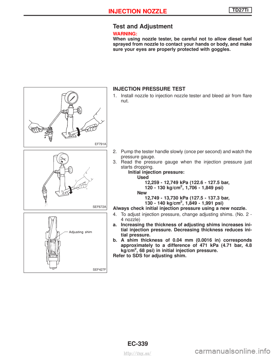
INJECTION PRESSURE TEST
1. Install nozzle to injection nozzle tester and bleed air from flarenut.
2. Pump the tester handle slowly (once per second) and watch the pressure gauge.
3. Read the pressure gauge when the injection pressure just starts dropping.Initial injection pressure: Used12,259 - 12,749 kPa (122.6 - 127.5 bar,
120 - 130 kg/cm
2, 1,706 - 1,849 psi)
New 12,749 - 13,730 kPa (127.5 - 137.3 bar,
130 - 140 kg/cm
2, 1,849 - 1,991 psi)
Always check initial injection pressure using a new nozzle.
4. To adjust injection pressure, change adjusting shims. (No. 2 - 4 nozzle)
a. Increasing the thickness of adjusting shims increases ini- tial injection pressure. Decreasing thickness reduces ini-
tial pressure.
b. A shim thickness of 0.04 mm (0.0016 in) corresponds approximately to a difference of 471 kPa (4.71 bar, 4.8
kg/cm
2, 68 psi) in initial injection pressure.
Refer to SDS for adjusting shim.
EF791A
SEF672A
SEF427F
INJECTION NOZZLETD27Ti
EC-339
http://vnx.su/
Page 616 of 1833
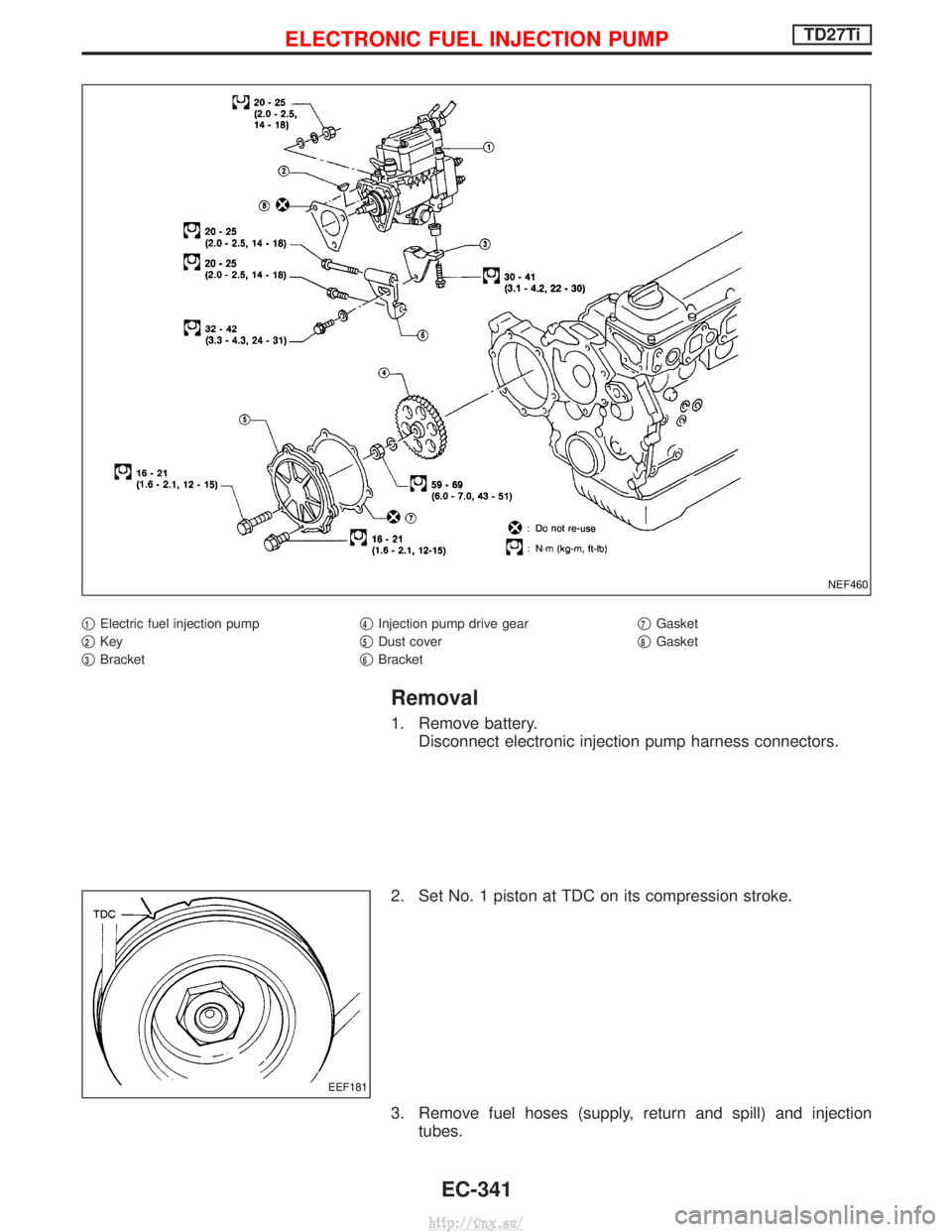
q1Electric fuel injection pump
q
2Key
q
3Bracket q
4Injection pump drive gear
q
5Dust cover
q
6Bracket q
7Gasket
q
8Gasket
Removal
1. Remove battery. Disconnect electronic injection pump harness connectors.
2. Set No. 1 piston at TDC on its compression stroke.
3. Remove fuel hoses (supply, return and spill) and injection tubes.
NEF460
EEF181
ELECTRONIC FUEL INJECTION PUMPTD27Ti
EC-341
http://vnx.su/
Page 617 of 1833
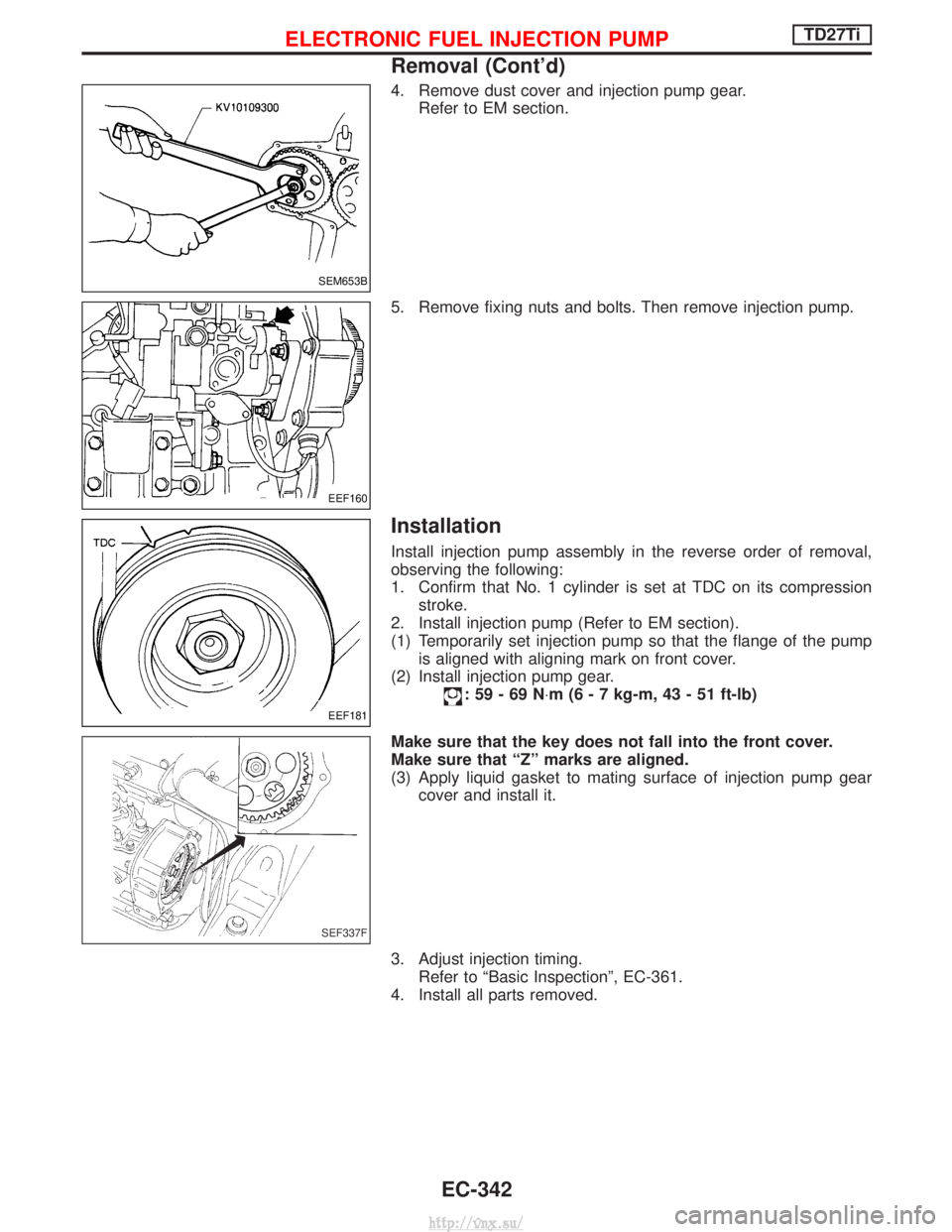
4. Remove dust cover and injection pump gear.Refer to EM section.
5. Remove fixing nuts and bolts. Then remove injection pump.
Installation
Install injection pump assembly in the reverse order of removal,
observing the following:
1. Confirm that No. 1 cylinder is set at TDC on its compression stroke.
2. Install injection pump (Refer to EM section).
(1) Temporarily set injection pump so that the flange of the pump is aligned with aligning mark on front cover.
(2) Install injection pump gear.
:59-69N ×m (6 - 7 kg-m, 43 - 51 ft-lb)
Make sure that the key does not fall into the front cover.
Make sure that ªZº marks are aligned.
(3) Apply liquid gasket to mating surface of injection pump gear cover and install it.
3. Adjust injection timing. Refer to ªBasic Inspectionº, EC-361.
4. Install all parts removed.
SEM653B
EEF160
EEF181
SEF337F
ELECTRONIC FUEL INJECTION PUMPTD27Ti
Removal (Cont'd)
EC-342
http://vnx.su/
Page 618 of 1833
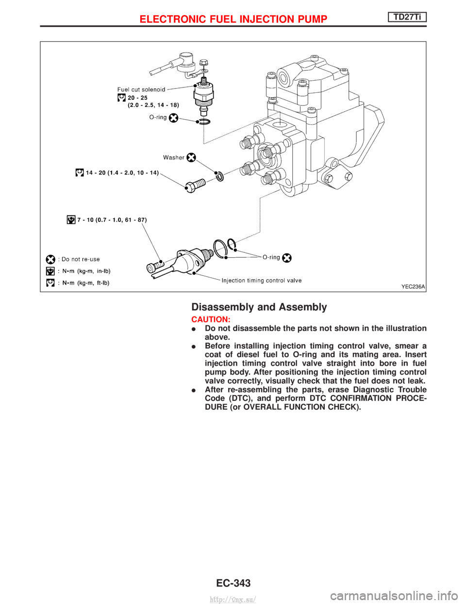
Disassembly and Assembly
CAUTION:
IDo not disassemble the parts not shown in the illustration
above.
I Before installing injection timing control valve, smear a
coat of diesel fuel to O-ring and its mating area. Insert
injection timing control valve straight into bore in fuel
pump body. After positioning the injection timing control
valve correctly, visually check that the fuel does not leak.
I After re-assembling the parts, erase Diagnostic Trouble
Code (DTC), and perform DTC CONFIRMATION PROCE-
DURE (or OVERALL FUNCTION CHECK).
YEC236A
ELECTRONIC FUEL INJECTION PUMPTD27Ti
EC-343
http://vnx.su/
Page 626 of 1833
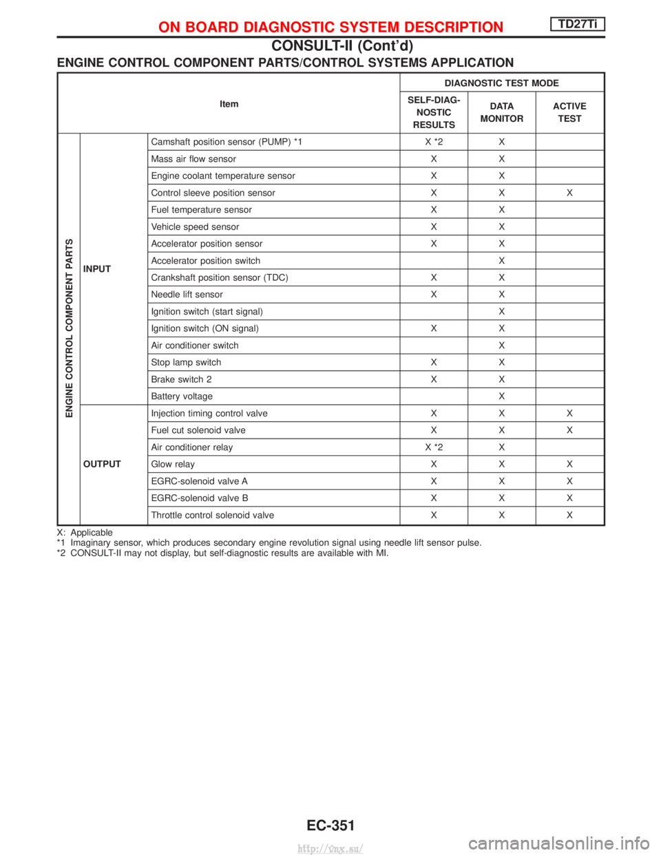
ENGINE CONTROL COMPONENT PARTS/CONTROL SYSTEMS APPLICATION
ItemDIAGNOSTIC TEST MODE
SELF-DIAG- NOSTIC
RESULTS D ATA
MONITOR ACTIVE
TEST
ENGINE CONTROL COMPONENT PARTS
INPUT Camshaft position sensor (PUMP) *1 X *2 X
Mass air flow sensor X X
Engine coolant temperature sensor X X
Control sleeve position sensor X X X
Fuel temperature sensor X X
Vehicle speed sensor X X
Accelerator position sensor X X
Accelerator position switch X
Crankshaft position sensor (TDC) X X
Needle lift sensor X X
Ignition switch (start signal) X
Ignition switch (ON signal) X X
Air conditioner switch X
Stop lamp switch X X
Brake switch 2 X X
Battery voltage X
OUTPUT Injection timing control valve X X X
Fuel cut solenoid valve X X X
Air conditioner relay X *2 X
Glow relay X X X
EGRC-solenoid valve A X X X
EGRC-solenoid valve B X X X
Throttle control solenoid valve X X X
X: Applicable
*1 Imaginary sensor, which produces secondary engine revolution signal using needle lift sensor pulse.
*2 CONSULT-II may not display, but self-diagnostic results are available with MI.
ON BOARD DIAGNOSTIC SYSTEM DESCRIPTIONTD27Ti
CONSULT-II (Cont'd)
EC-351
http://vnx.su/
Page 627 of 1833
![NISSAN TERRANO 2004 Service Manual Online SELF-DIAGNOSTIC MODE
Regarding items detected in ªSELF-DIAG RESULTSº mode, refer to ªTROUBLE DIAGNOSIS Ð INDEXº,
EC-313.
DATA MONITOR MODE
Monitored item
[Unit]ECM
input
signals Main
signals Desc](/img/5/57394/w960_57394-626.png "NISSAN TERRANO 2004 Service Manual Online SELF-DIAGNOSTIC MODE
Regarding items detected in ªSELF-DIAG RESULTSº mode, refer to ªTROUBLE DIAGNOSIS Ð INDEXº,
EC-313.
DATA MONITOR MODE
Monitored item
[Unit]ECM
input
signals Main
signals Desc")
SELF-DIAGNOSTIC MODE
Regarding items detected in ªSELF-DIAG RESULTSº mode, refer to ªTROUBLE DIAGNOSIS Ð INDEXº,
EC-313.
DATA MONITOR MODE
Monitored item
[Unit]ECM
input
signals Main
signals Description
Remarks
CKPS×RPM
(TDC) [rpm]
qq
I The engine speed computed from the
crankshaft position sensor (TDC) signal
is displayed.
CMPS×RPM -
PUMP [rpm]
qqI The engine speed computed from the
needle lift sensor signal is displayed.
COOLAN TEMP/S
[ÉC] or [ÉF]
qq
I The engine coolant temperature (deter-
mined by the signal voltage of the engine
coolant temperature sensor) is displayed. I
When the engine coolant temperature
sensor is open or short-circuited, ECM
enters fail-safe mode. The same data as
the fuel temperature is displayed.
VHCL SPEED SE
[km/h] or [mph]
qqI The vehicle speed computed from the
vehicle speed sensor signal is displayed.
FUEL TEMP SEN
[ÉC] or [ÉF]
qq
I The fuel temperature (determined by the
signal voltage of the fuel temperature
sensor) is displayed.
ACCEL POS SEN [V]
qqI The accelerator position sensor signal
voltage is displayed.
OFF ACCEL POS
[ON/OFF]
qqI Indicates [ON/OFF] condition from the
accelerator position switch signal. I
Signal at approximately 9É opened.
C/SLEEV POS/S [V]
qqI The control sleeve position sensor signal
voltage is displayed.
BATTERY VOLT [V]
qqI The power supply voltage of ECM is dis-
played.
START SIGNAL
[ON/OFF]
qqI Indicates [ON/OFF] condition from the
starter signal. I
After starting the engine, [OFF] is dis-
played regardless of the starter signal.
AIR COND SIG
[ON/OFF]
qq
I Indicates [ON/OFF] condition of the air
conditioner switch as determined by the
air conditioner signal.
BRAKE SW
[ON/OFF]
qI Indicates [ON/OFF] condition of the stop
lamp switch.
BRAKE SW2
[ON/OFF]
qI Indicates [ON/OFF] condition of the
brake switch 2.
IGN SW
[ON/OFF]
qqI Indicates [ON/OFF] condition from igni-
tion switch.
MAS AIR/FL SE [V]
qqI The signal voltage of the mass air flow
sensor is displayed. I
When the engine is stopped, a certain
value is indicated.
ACT INJ TIMG [É]
q
I The actual injection timing angle deter-
mined by the ECM (an approximate aver-
age angle between injection start and
end from TDC) is displayed.
TARGET F/INJ
[mm
3/stroke]qI The target fuel injection quantity (deter-
mined by the ECM according to the input
signal) is indicated.
NOTE:
Any monitored item that does not match the vehicle being diagnosed is deleted from the display automatically.
ON BOARD DIAGNOSTIC SYSTEM DESCRIPTIONTD27Ti
CONSULT-II (Cont'd)
EC-352
http://vnx.su/
Page 632 of 1833
Introduction
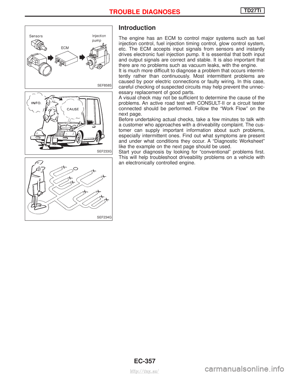
The engine has an ECM to control major systems such as fuel
injection control, fuel injection timing control, glow control system,
etc. The ECM accepts input signals from sensors and instantly
drives electronic fuel injection pump. It is essential that both input
and output signals are correct and stable. It is also important that
there are no problems such as vacuum leaks, with the engine.
It is much more difficult to diagnose a problem that occurs intermit-
tently rather than continuously. Most intermittent problems are
caused by poor electric connections or faulty wiring. In this case,
careful checking of suspected circuits may help prevent the unnec-
essary replacement of good parts.
A visual check may not be sufficient to determine the cause of the
problems. An active road test with CONSULT-II or a circuit tester
connected should be performed. Follow the ªWork Flowº on the
next page.
Before undertaking actual checks, take a few minutes to talk with
a customer who approaches with a driveability complaint. The cus-
tomer can supply important information about such problems,
especially intermittent ones. Find out what symptoms are present
and under what conditions they occur. A ªDiagnostic Worksheetº
like the example on the next page should be used.
Start your diagnosis by looking for ªconventionalº problems first.
This will help troubleshoot driveability problems on a vehicle with
an electronically controlled engine.
SEF858S
SEF233G
SEF234G
TROUBLE DIAGNOSESTD27Ti
EC-357
http://vnx.su/
Page 636 of 1833

Basic Inspection
Precaution:
Perform Basic Inspection without electrical or mechanical
loads applied;
IHeadlamp switch is OFF,
I Air conditioner switch is OFF,
I Rear defogger switch is OFF,
I Steering wheel is in the straight-ahead position, etc.
BEFORE STARTING
1. Check service records for any recent
repairs that may indicate a related
problem, or the current need for
scheduled maintenance.
2. Open engine hood and check the fol- lowing:
I Harness connectors for improper con-
nections
I Vacuum hoses for splits, kinks, or
improper connections
I Wiring for improper connections,
pinches, or cuts
3.Using priming pump, bleed air from fuel system. Refer to ªFuel Filter Checkº in
MA section.
CONNECT CONSULT-II TO THE
VEHICLE.
Connect ªCONSULT-IIº to the data link
connector for CONSULT-II and select
ªENGINEº from the menu.
DOES ENGINE START?
Ye s
ENo Turn ignition switch to
ªLOCKº position, wait 5
seconds and then start
engine. If engine fails to
start, check diagnostic
trouble code (DTC).
Run engine for 10 minutes.
CHECK IDLE SPEED.
Read engine idle speed in ªDATA
MONITORº mode with CONSULT-II.
725 rpm 50 (in N position)
----------------------------------------------------------------------------------------------------------------------------------- -OR------------------------------------------------------------------------------------------------------------------------------------
Check idle speed using tachometer
tester.
725 rpm 50 (in N position)
(Go to qAon next page.)
SEF142I
NEF463
NRS122
NEF464
SEF817Y
H
H
H
H
H
TROUBLE DIAGNOSESTD27Ti
EC-361
http://vnx.su/
Page 637 of 1833
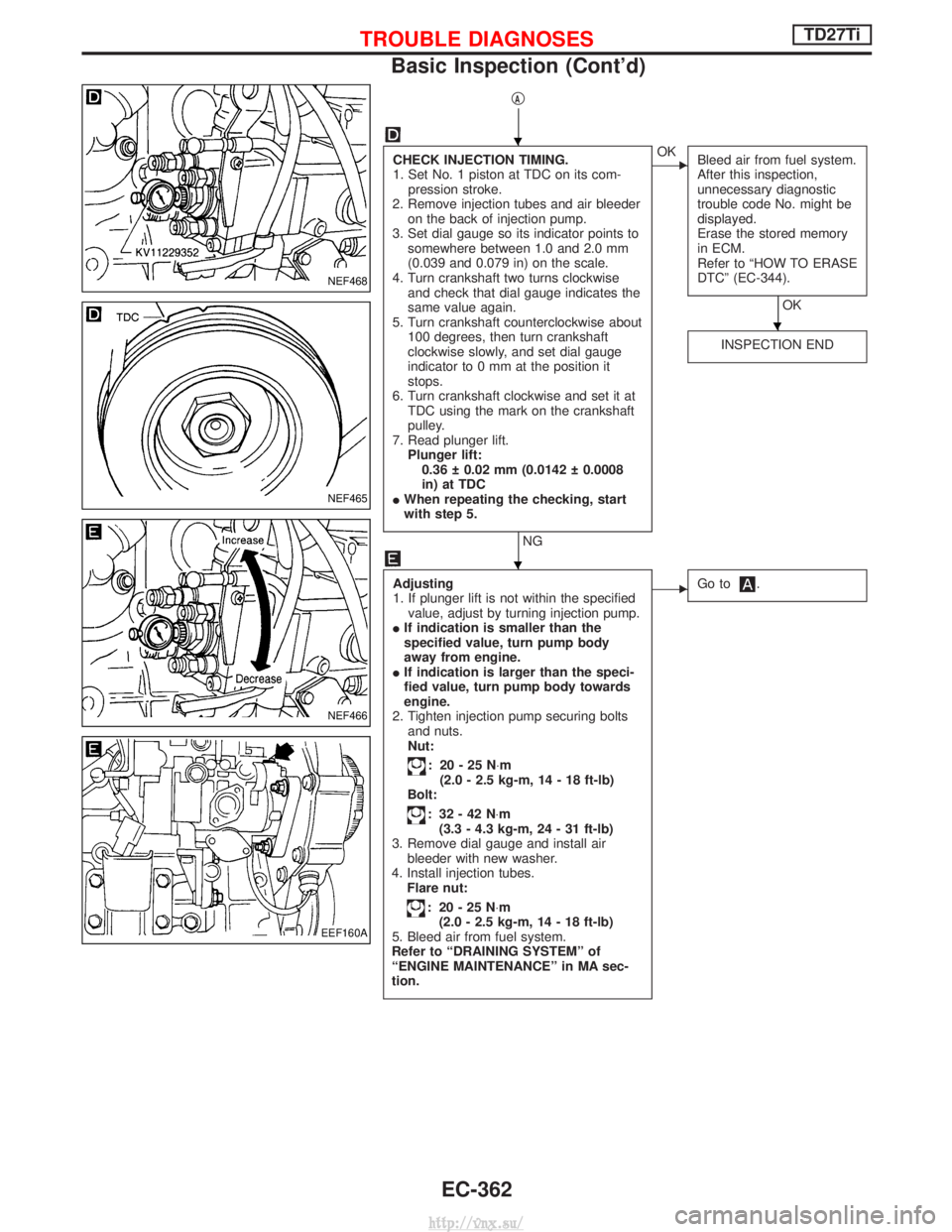
qA
CHECK INJECTION TIMING.
1. Set No. 1 piston at TDC on its com-pression stroke.
2. Remove injection tubes and air bleeder on the back of injection pump.
3. Set dial gauge so its indicator points to somewhere between 1.0 and 2.0 mm
(0.039 and 0.079 in) on the scale.
4. Turn crankshaft two turns clockwise and check that dial gauge indicates the
same value again.
5. Turn crankshaft counterclockwise about 100 degrees, then turn crankshaft
clockwise slowly, and set dial gauge
indicator to 0 mm at the position it
stops.
6. Turn crankshaft clockwise and set it at TDC using the mark on the crankshaft
pulley.
7. Read plunger lift. Plunger lift:0.36 0.02 mm (0.0142 0.0008
in) at TDC
I When repeating the checking, start
with step 5.
NG
EOK
Bleed air from fuel system.
After this inspection,
unnecessary diagnostic
trouble code No. might be
displayed.
Erase the stored memory
in ECM.
Refer to ªHOW TO ERASE
DTCº (EC-344).
OK
INSPECTION END
Adjusting
1. If plunger lift is not within the specified value, adjust by turning injection pump.
I If indication is smaller than the
specified value, turn pump body
away from engine.
I If indication is larger than the speci-
fied value, turn pump body towards
engine.
2. Tighten injection pump securing bolts and nuts.
Nut:
: 20-25N ×m
(2.0 - 2.5 kg-m, 14 - 18 ft-lb)
Bolt:
: 32-42N ×m
(3.3 - 4.3 kg-m, 24 - 31 ft-lb)
3. Remove dial gauge and install air bleeder with new washer.
4. Install injection tubes. Flare nut:
: 20-25N ×m
(2.0 - 2.5 kg-m, 14 - 18 ft-lb)
5. Bleed air from fuel system.
Refer to ªDRAINING SYSTEMº of
ªENGINE MAINTENANCEº in MA sec-
tion.
EGo to.
NEF468
NEF465
NEF466
EEF160A
H
H
H
TROUBLE DIAGNOSESTD27Ti
Basic Inspection (Cont'd)
EC-362
http://vnx.su/
Page 638 of 1833
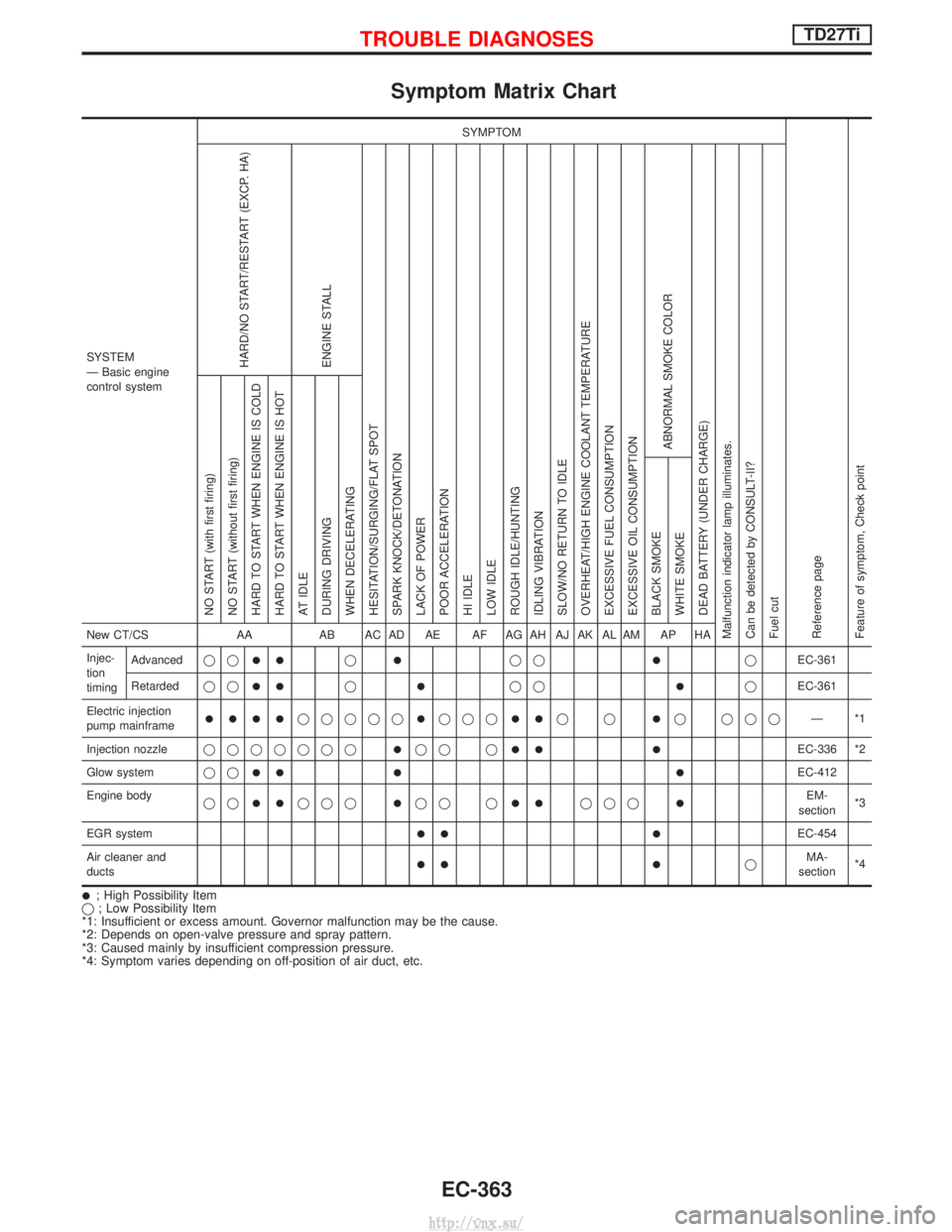
Symptom Matrix Chart
SYSTEM
Ð Basic engine
control systemSYMPTOM
Reference page
Feature of symptom, Check pointHARD/NO START/RESTART (EXCP. HA)
ENGINE STALL
HESITATION/SURGING/FLAT SPOT
SPARK KNOCK/DETONATION
LACK OF POWER
POOR ACCELERATION
HI IDLE
LOW IDLE
ROUGH IDLE/HUNTING
IDLING VIBRATION
SLOW/NO RETURN TO IDLE
OVERHEAT/HIGH ENGINE COOLANT TEMPERATURE
EXCESSIVE FUEL CONSUMPTION
EXCESSIVE OIL CONSUMPTION ABNORMAL SMOKE COLOR
DEAD BATTERY (UNDER CHARGE)
Malfunction indicator lamp illuminates.
Can be detected by CONSULT-II?
Fuel cut NO START (with first firing)
NO START (without first firing)
HARD TO START WHEN ENGINE IS COLD
HARD TO START WHEN ENGINE IS HOT
AT IDLE
DURING DRIVING
WHEN DECELERATING
BLACK SMOKE
WHITE SMOKENew CT/CS
AAAB AC AD AE AF AG AH AJ AK AL AM AP HA
Injec-
tion
timing Advanced
qq
IIqIqqIqEC-361
Retarded qq
IIqIqqIqEC-361
Electric injection
pump mainframe
IIIIqqqqqIqqqIIqqIq qqq Ð*1
Injection nozzle qqqqqqq
Iqq qIIIEC-336 *2
Glow system qq
III IEC-412
Engine body qq
IIqqqIqq qIIqqqIEM-
section *3
EGR system
II IEC-454
Air cleaner and
ducts
II IqMA-
section *4
I; High Possibility Item
q ; Low Possibility Item
*1: Insufficient or excess amount. Governor malfunction may be the cause.
*2: Depends on open-valve pressure and spray pattern.
*3: Caused mainly by insufficient compression pressure.
*4: Symptom varies depending on off-position of air duct, etc.
TROUBLE DIAGNOSESTD27Ti
EC-363
http://vnx.su/