brake light NISSAN TERRANO 2004 Service Repair Manual
[x] Cancel search | Manufacturer: NISSAN, Model Year: 2004, Model line: TERRANO, Model: NISSAN TERRANO 2004Pages: 1833, PDF Size: 53.42 MB
Page 44 of 1833
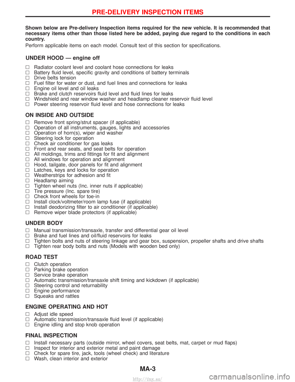
Shown below are Pre-delivery Inspection items required for the new vehicle. It is recommended that
necessary items other than those listed here be added, paying due regard to the conditions in each
country.
Perform applicable items on each model. Consult text of this section for specifications.
UNDER HOOD Ð engine off
lRadiator coolant level and coolant hose connections for leaks
l Battery fluid level, specific gravity and conditions of battery terminals
l Drive belts tension
l Fuel filter for water or dust, and fuel lines and connections for leaks
l Engine oil level and oil leaks
l Brake and clutch reservoirs fluid level and fluid lines for leaks
l Windshield and rear window washer and headlamp cleaner reservoir fluid level
l Power steering reservoir fluid level and hose connections for leaks
ON INSIDE AND OUTSIDE
lRemove front spring/strut spacer (if applicable)
l Operation of all instruments, gauges, lights and accessories
l Operation of horn(s), wiper and washer
l Steering lock for operation
l Check air conditioner for gas leaks
l Front and rear seats, and seat belts for operation
l All moldings, trims and fittings for fit and alignment
l All windows for operation and alignment
l Hood, tailgate, door panels for fit and alignment
l Latches, keys and locks for operation
l Weatherstrips for adhesion and fit
l Headlamp aiming
l Tighten wheel nuts (Inc. inner nuts if applicable)
l Tire pressure (Inc. spare tire)
l Check front wheels for toe-in
l Install clock/voltmeter/room lamp fuse (if applicable)
l Install deodorizing filter to air conditioner (if applicable)
l Remove wiper blade protectors (if applicable)
UNDER BODY
lManual transmission/transaxle, transfer and differential gear oil level
l Brake and fuel lines and oil/fluid reservoirs for leaks
l Tighten bolts and nuts of steering linkage and gear box, suspension, propeller shafts and drive shafts
l Tighten rear body bolts and nuts (Models with wooden bed only)
ROAD TEST
lClutch operation
l Parking brake operation
l Service brake operation
l Automatic transmission/transaxle shift timing and kickdown (if applicable)
l Steering control and returnability
l Engine performance
l Squeaks and rattles
ENGINE OPERATING AND HOT
lAdjust idle speed
l Automatic transmission/transaxle fluid level (if applicable)
l Engine idling and stop knob operation
FINAL INSPECTION
lInstall necessary parts (outside mirror, wheel covers, seat belts, mat, carpet or mud flaps)
l Inspect for interior and exterior metal and paint damage
l Check for spare tire, jack, tools (wheel check) and literature
l Wash, clean interior and exterior
PRE-DELIVERY INSPECTION ITEMS
MA-3
http://vnx.su/
Page 45 of 1833
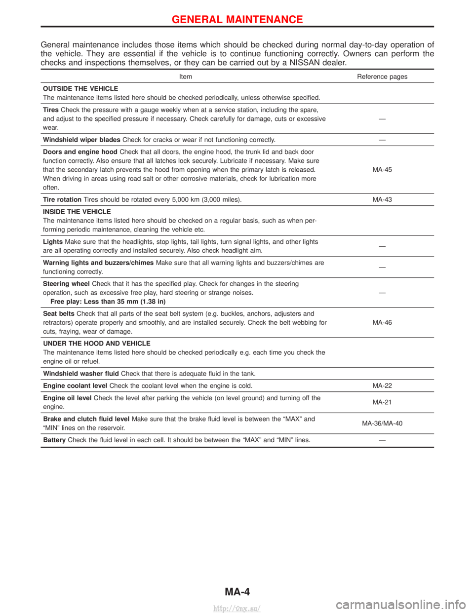
General maintenance includes those items which should be checked during normal day-to-day operation of
the vehicle. They are essential if the vehicle is to continue functioning correctly. Owners can perform the
checks and inspections themselves, or they can be carried out by a NISSAN dealer.
ItemReference pages
OUTSIDE THE VEHICLE
The maintenance items listed here should be checked periodically, unless otherwise specified.
Tires Check the pressure with a gauge weekly when at a service station, including the spare,
and adjust to the specified pressure if necessary. Check carefully for damage, cuts or excessive
wear. Ð
Windshield wiper blades Check for cracks or wear if not functioning correctly. Ð
Doors and engine hood Check that all doors, the engine hood, the trunk lid and back door
function correctly. Also ensure that all latches lock securely. Lubricate if necessary. Make sure
that the secondary latch prevents the hood from opening when the primary latch is released.
When driving in areas using road salt or other corrosive materials, check for lubrication more
often. MA-45
Tire rotation Tires should be rotated every 5,000 km (3,000 miles). MA-43
INSIDE THE VEHICLE
The maintenance items listed here should be checked on a regular basis, such as when per-
forming periodic maintenance, cleaning the vehicle etc.
Lights Make sure that the headlights, stop lights, tail lights, turn signal lights, and other lights
are all operating correctly and installed securely. Also check headlight aim. Ð
Warning lights and buzzers/chimes Make sure that all warning lights and buzzers/chimes are
functioning correctly. Ð
Steering wheel Check that it has the specified play. Check for changes in the steering
operation, such as excessive free play, hard steering or strange noises. Free play: Less than 35 mm (1.38 in) Ð
Seat belts Check that all parts of the seat belt system (e.g. buckles, anchors, adjusters and
retractors) operate properly and smoothly, and are installed securely. Check the belt webbing for
cuts, fraying, wear of damage. MA-46
UNDER THE HOOD AND VEHICLE
The maintenance items listed here should be checked periodically e.g. each time you check the
engine oil or refuel.
Windshield washer fluid Check that there is adequate fluid in the tank.
Engine coolant level Check the coolant level when the engine is cold. MA-22
Engine oil level Check the level after parking the vehicle (on level ground) and turning off the
engine. MA-21
Brake and clutch fluid level Make sure that the brake fluid level is between the ªMAXº and
ªMINº lines on the reservoir. MA-36/MA-40
Battery Check the fluid level in each cell. It should be between the ªMAXº and ªMINº lines. Ð
GENERAL MAINTENANCE
MA-4
http://vnx.su/
Page 67 of 1833
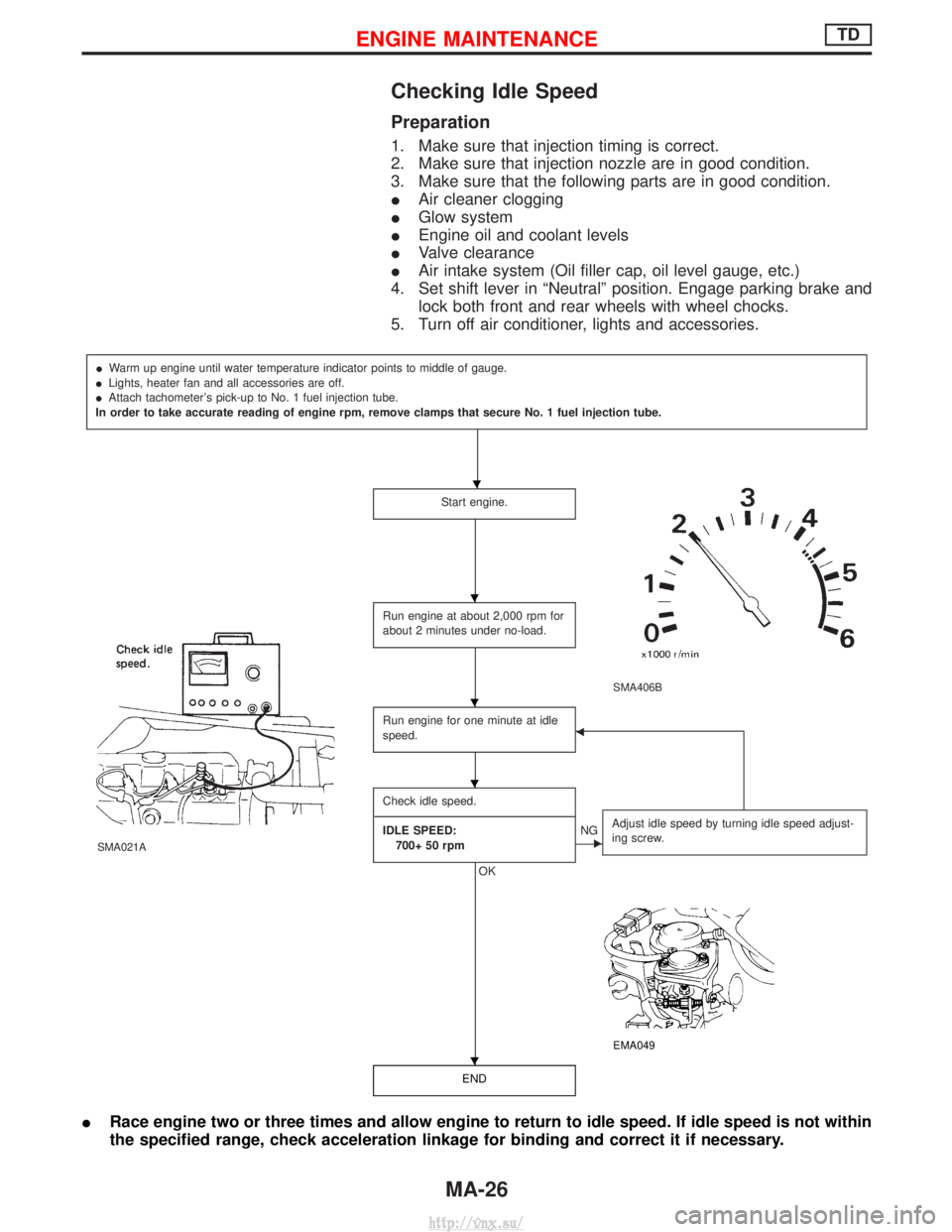
Checking Idle Speed
Preparation
1. Make sure that injection timing is correct.
2. Make sure that injection nozzle are in good condition.
3. Make sure that the following parts are in good condition.
IAir cleaner clogging
I Glow system
I Engine oil and coolant levels
I Valve clearance
I Air intake system (Oil filler cap, oil level gauge, etc.)
4. Set shift lever in ªNeutralº position. Engage parking brake and lock both front and rear wheels with wheel chocks.
5. Turn off air conditioner, lights and accessories.
I Warm up engine until water temperature indicator points to middle of gauge.
I Lights, heater fan and all accessories are off.
I Attach tachometer's pick-up to No. 1 fuel injection tube.
In order to take accurate reading of engine rpm, remove clamps that secure No. 1 fuel injection tube.
Start engine.
SMA406B
SMA021A
Run engine at about 2,000 rpm for
about 2 minutes under no-load.
Run engine for one minute at idle
speed.F
Check idle speed.
---------------------------------------------------------------------------------------------------------------------------------------------------------------------------------------------------------------------------------- IDLE SPEED: 700+ 50 rpm
OK
ENG Adjust idle speed by turning idle speed adjust-
ing screw.
EMA049
END
I
Race engine two or three times and allow engine to return to idle speed. If idle speed is not within
the specified range, check acceleration linkage for binding and correct it if necessary.
H
H
H
H
H
ENGINE MAINTENANCETD
MA-26
http://vnx.su/
Page 341 of 1833
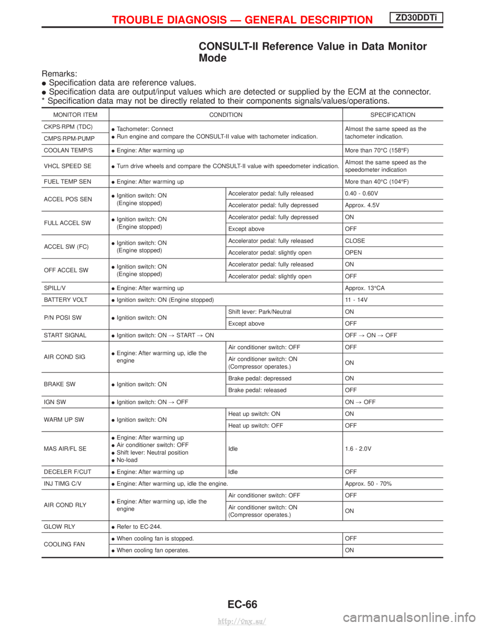
CONSULT-II Reference Value in Data Monitor
Mode
Remarks:
ISpecification data are reference values.
I Specification data are output/input values which are detected or supplied by the ECM at the connector.
* Specification data may not be directly related to their components signals/values/operations.
MONITOR ITEM CONDITION SPECIFICATION
CKPS×RPM (TDC) ITachometer: Connect
I Run engine and compare the CONSULT-II value with tachometer indication. Almost the same speed as the
tachometer indication.
CMPS×RPM-PUMP
COOLAN TEMP/S IEngine: After warming up More than 70ÉC (158ÉF)
VHCL SPEED SE ITurn drive wheels and compare the CONSULT-II value with speedometer indication. Almost the same speed as the
speedometer indication
FUEL TEMP SEN IEngine: After warming up More than 40ÉC (104ÉF)
ACCEL POS SEN I
Ignition switch: ON
(Engine stopped) Accelerator pedal: fully released
0.40 - 0.60V
Accelerator pedal: fully depressed Approx. 4.5V
FULL ACCEL SW I
Ignition switch: ON
(Engine stopped) Accelerator pedal: fully depressed ON
Except above
OFF
ACCEL SW (FC) I
Ignition switch: ON
(Engine stopped) Accelerator pedal: fully released
CLOSE
Accelerator pedal: slightly open OPEN
OFF ACCEL SW I
Ignition switch: ON
(Engine stopped) Accelerator pedal: fully released
ON
Accelerator pedal: slightly open OFF
SPILL/V IEngine: After warming up Approx. 13ÉCA
BATTERY VOLT IIgnition switch: ON (Engine stopped) 11 - 14V
P/N POSI SW IIgnition switch: ON Shift lever: Park/Neutral
ON
Except above OFF
START SIGNAL IIgnition switch: ON ,START ,ON OFF ,ON ,OFF
AIR COND SIG I
Engine: After warming up, idle the
engine Air conditioner switch: OFF OFF
Air conditioner switch: ON
(Compressor operates.)
ON
BRAKE SW IIgnition switch: ON Brake pedal: depressed ON
Brake pedal: released OFF
IGN SW IIgnition switch: ON ,OFF ON ,OFF
WARM UP SW IIgnition switch: ON Heat up switch: ON ON
Heat up switch: OFF OFF
MAS AIR/FL SE I
Engine: After warming up
I Air conditioner switch: OFF
I Shift lever: Neutral position
I No-load Idle 1.6 - 2.0V
DECELER F/CUT IEngine: After warming up Idle OFF
INJ TIMG C/V IEngine: After warming up, idle the engine. Approx. 50 - 70%
AIR COND RLY I
Engine: After warming up, idle the
engine Air conditioner switch: OFF OFF
Air conditioner switch: ON
(Compressor operates.)
ON
GLOW RLY IRefer to EC-244.
COOLING FAN I
When cooling fan is stopped. OFF
I When cooling fan operates. ON
TROUBLE DIAGNOSIS Ð GENERAL DESCRIPTIONZD30DDTi
EC-66
http://vnx.su/
Page 815 of 1833
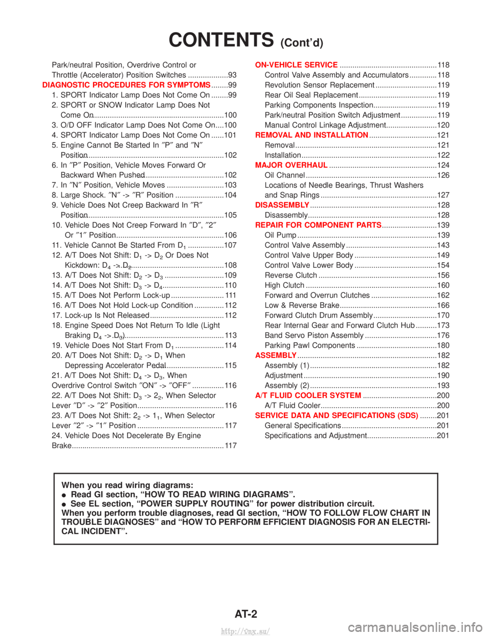
Park/neutral Position, Overdrive Control or
Throttle (Accelerator) Position Switches ...................93
DIAGNOSTIC PROCEDURES FOR SYMPTOMS ........99
1. SPORT Indicator Lamp Does Not Come On ........99
2. SPORT or SNOW Indicator Lamp Does Not Come On.................................................................100
3. O/D OFF Indicator Lamp Does Not Come On....100
4. SPORT Indicator Lamp Does Not Come On ......101
5. Engine Cannot Be Started In ²P² and ²N²
Position....................................................................102
6. In ²P² Position, Vehicle Moves Forward Or
Backward When Pushed.........................................102
7. In ²N² Position, Vehicle Moves ...........................103
8. Large Shock. ²N² ->²R² Position .......................104
9. Vehicle Does Not Creep Backward In ²R²
Position....................................................................105
10. Vehicle Does Not Creep Forward In ²D² ,²2²
Or ²1² Position.........................................................106
11. Vehicle Cannot Be Started From D
1.................107
12. A/T Does Not Shift: D
1-> D2Or Does Not
Kickdown: D
4-> D2..................................................108
13. A/T Does Not Shift: D
2-> D3............................109
14. A/T Does Not Shift: D
3-> D4............................. 110
15. A/T Does Not Perform Lock-up ......................... 111
16. A/T Does Not Hold Lock-up Condition .............. 112
17. Lock-up Is Not Released ................................... 112
18. Engine Speed Does Not Return To Idle (Light Braking D
4-> D3)..................................................... 113
19. Vehicle Does Not Start From D
1....................... 114
20. A/T Does Not Shift: D
2-> D1When
Depressing Accelerator Pedal................................. 115
21. A/T Does Not Shift: D
4-> D3, When
Overdrive Control Switch ²ON² ->²OFF² ............... 116
22. A/T Does Not Shift: D
3-> 22, When Selector
Lever ²D² ->²2² Position......................................... 116
23. A/T Does Not Shift: 2
2-> 11, When Selector
Lever ²2² ->²1² Position ......................................... 117
24. Vehicle Does Not Decelerate By Engine
Brake........................................................................\
117 ON-VEHICLE SERVICE
.............................................. 118
Control Valve Assembly and Accumulators ............. 118
Revolution Sensor Replacement ............................. 119
Rear Oil Seal Replacement ..................................... 119
Parking Components Inspection.............................. 119
Park/neutral Position Switch Adjustment ................. 119
Manual Control Linkage Adjustment........................120
REMOVAL AND INSTALLATION ................................121
Removal ...................................................................121
Installation ................................................................122
MAJOR OVERHAUL ...................................................124
Oil Channel ..............................................................126
Locations of Needle Bearings, Thrust Washers
and Snap Rings .......................................................127
DISASSEMBLY ............................................................128
Disassembly.............................................................128
REPAIR FOR COMPONENT PARTS ..........................139
Oil Pump ..................................................................139
Control Valve Assembly ...........................................143
Control Valve Upper Body .......................................149
Control Valve Lower Body .......................................154
Reverse Clutch ........................................................156
High Clutch ..............................................................160
Forward and Overrun Clutches ...............................162
Low & Reverse Brake..............................................166
Forward Clutch Drum Assembly ..............................170
Rear Internal Gear and Forward Clutch Hub ..........173
Band Servo Piston Assembly ..................................176
Parking Pawl Components ......................................180
ASSEMBLY ..................................................................182
Assembly (1) ............................................................182
Adjustment ...............................................................190
Assembly (2) ............................................................193
A/T FLUID COOLER SYSTEM ...................................200
A/T Fluid Cooler.......................................................200
SERVICE DATA AND SPECIFICATIONS (SDS) ........201
General Specifications .............................................201
Specifications and Adjustment.................................201
When you read wiring diagrams:
I Read GI section, ªHOW TO READ WIRING DIAGRAMSº.
I See EL section, ªPOWER SUPPLY ROUTINGº for power distribution circuit.
When you perform trouble diagnoses, read GI section, ªHOW TO FOLLOW FLOW CHART IN
TROUBLE DIAGNOSESº and ªHOW TO PERFORM EFFICIENT DIAGNOSIS FOR AN ELECTRI-
CAL INCIDENTº.
CONTENTS(Cont'd)
AT- 2
http://vnx.su/
Page 837 of 1833
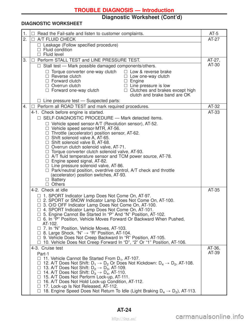
DIAGNOSTIC WORKSHEET
1.lRead the Fail-safe and listen to customer complaints. AT-5
2. lA/T FLUID CHECK AT-27
l Leakage (Follow specified procedure)
l Fluid condition
l Fluid level
3. lPerform STALL TEST and LINE PRESSURE TEST. AT-27,
AT-30
l Stall test Ð Mark possible damaged components/others.
l Torque converter one-way clutch
l Reverse clutch
l Forward clutch
l Overrun clutch
l Forward one-way clutch l
Low & reverse brake
l Low one-way clutch
l Engine
l Line pressure is low
l Clutches and brakes except high
clutch and brake band are OK
l Line pressure test Ð Suspected parts:
4. lPerform all ROAD TEST and mark required procedures. AT-32
4-1. Check before engine is started. AT-33 l SELF-DIAGNOSTIC PROCEDURE Ð Mark detected items.
l Vehicle speed sensor×A/T (Revolution sensor), AT-52.
l Vehicle speed sensor×MTR, AT-56.
l Throttle (accelerator) position sensor, AT-62.
l Shift solenoid valve A, AT-65.
l Shift solenoid valve B, AT-68.
l Overrun clutch solenoid valve, AT-71.
l Torque converter clutch solenoid valve, AT-93.
l A/T fluid temperature sensor and TCM power source, AT-78.
l Engine speed signal, AT-82.
l Line pressure solenoid valve, AT-86.
l Park/neutral position, overdrive control, A/T check and throttle
(accelerator) position switches, AT-93.
l Battery
l Others
4-2. Check at idle AT-35 l 1. SPORT Indicator Lamp Does Not Come On, AT-97.
l 2. SPORT or SNOW Indicator Lamp Does Not Come On, AT-100.
l 3. O/D OFF Indicator Lamp Does Not Come On, AT-100.
l 4. SPORT Indicator Lamp Does Not Come On, AT-101.
l 5. Engine Cannot Be Started In ªPº And ªNº Position, AT-102.
l 6. In ªPº Position, Vehicle Moves Forward Or Backward When Pushed,
AT-102.
l 7. In ªNº Position, Vehicle Moves, AT-103.
l 8. Large Shock. ªNº ,ªRº Position, AT-104.
l 9. Vehicle Does Not Creep Backward In ªRº Position, AT-105.
l 10. Vehicle Does Not Creep Forward In ªDº, ª2º Or ª1º Position, AT-106.
4-3. Cruise test AT-36,
AT-39
Part-1
l 11. Vehicle Cannot Be Started From D
1, AT-107.
l 12. A/T Does Not Shift: D
1,D2Or Does Not Kickdown: D4,D2, AT-108.
l 13. A/T Does Not Shift: D
2,D3, AT-109.
l 14. A/T Does Not Shift: D
3,D4, AT-110.
l 15. A/T Does Not Perform Lock-up, AT-111.
l 16. A/T Does Not Hold Lock-up Condition, AT-112.
l 17. Lock-up Is Not Released, AT-112.
l 18. Engine Speed Does Not Return To Idle (Light Braking D
4,D3), AT-113.
TROUBLE DIAGNOSIS Ð Introduction
Diagnostic Worksheet (Cont'd)
AT-24
http://vnx.su/
Page 840 of 1833
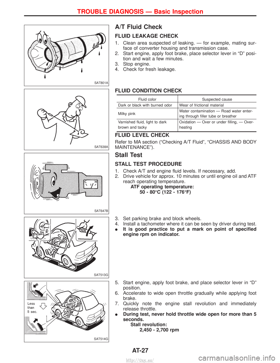
A/T Fluid Check
FLUID LEAKAGE CHECK
1. Clean area suspected of leaking. Ð for example, mating sur-face of converter housing and transmission case.
2. Start engine, apply foot brake, place selector lever in ªDº posi- tion and wait a few minutes.
3. Stop engine.
4. Check for fresh leakage.
FLUID CONDITION CHECK
Fluid color Suspected cause
Dark or black with burned odor Wear of frictional material
Milky pink Water contamination Ð Road water enter-
ing through filler tube or breather
Varnished fluid, light to dark
brown and tacky Oxidation Ð Over or under filling, Ð Over-
heating
FLUID LEVEL CHECK
Refer to MA section (ªChecking A/T Fluidº, ªCHASSIS AND BODY
MAINTENANCEº).
Stall Test
STALL TEST PROCEDURE
1. Check A/T and engine fluid levels. If necessary, add.
2. Drive vehicle for approx. 10 minutes or until engine oil and ATF
reach operating temperature.ATF operating temperature: 50 - 80ÉC (122 - 176ÉF)
3. Set parking brake and block wheels.
4. Install a tachometer where it can be seen by driver during test.
I It is good practice to put a mark on point of specified
engine rpm on indicator.
5. Start engine, apply foot brake, and place selector lever in ªDº position.
6. Accelerate to wide open throttle gradually while applying foot brake.
7. Quickly note the engine stall revolution and immediately release throttle.
I During test, never hold throttle wide open for more than 5
seconds.
Stall revolution: 2,450 - 2,700 rpm
SAT801A
SAT638A
SAT647B
SAT513G
SAT514G
TROUBLE DIAGNOSIS Ð Basic Inspection
AT-27
http://vnx.su/
Page 853 of 1833
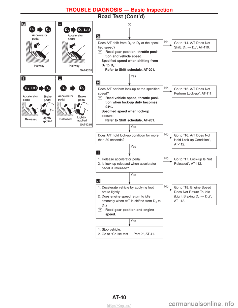
qA
Does A/T shift from D3to D4at the speci-
fied speed?
Read gear position, throttle posi-
tion and vehicle speed.
Specified speed when shifting from
D
3to D4:
Refer to Shift schedule, AT-201.
Ye s
ENo Go to ª14. A/T Does Not
Shift: D
3,D4º, AT-110.
Does A/T perform lock-up at the specified
speed?
Read vehicle speed, throttle posi-
tion when lock-up duty becomes
94%.
Specified speed when lock-up
occurs: Refer to Shift schedule, AT-201.
Ye s
ENo Go to ª15. A/T Does Not
Perform Lock-upº, AT-111.
Does A/T hold lock-up condition for more
than 30 seconds?
Ye s
ENoGo to ª16. A/T Does Not
Hold Lock-up Conditionº,
AT-112.
1. Release accelerator pedal.
2. Is lock-up released when accelerator pedal is released?
Ye s
ENo Go to ª17. Lock-up Is Not
Releasedº, AT-112.
1. Decelerate vehicle by applying foot
brake lightly.
2. Does engine speed return to idle smoothly when A/T is shifted from D
4to
D
3?
Read gear position and engine
speed.
Ye s
ENo Go to ª18. Engine Speed
Does Not Return To Idle
(Light Braking D
4,D3)º,
AT-113.
1. Stop vehicle.
2. Go to ªCruise test Ð Part 2º, AT-41.
SAT402H
SAT403H
H
H
H
H
H
H
TROUBLE DIAGNOSIS Ð Basic Inspection
Road Test (Cont'd)
AT-40
http://vnx.su/
Page 855 of 1833
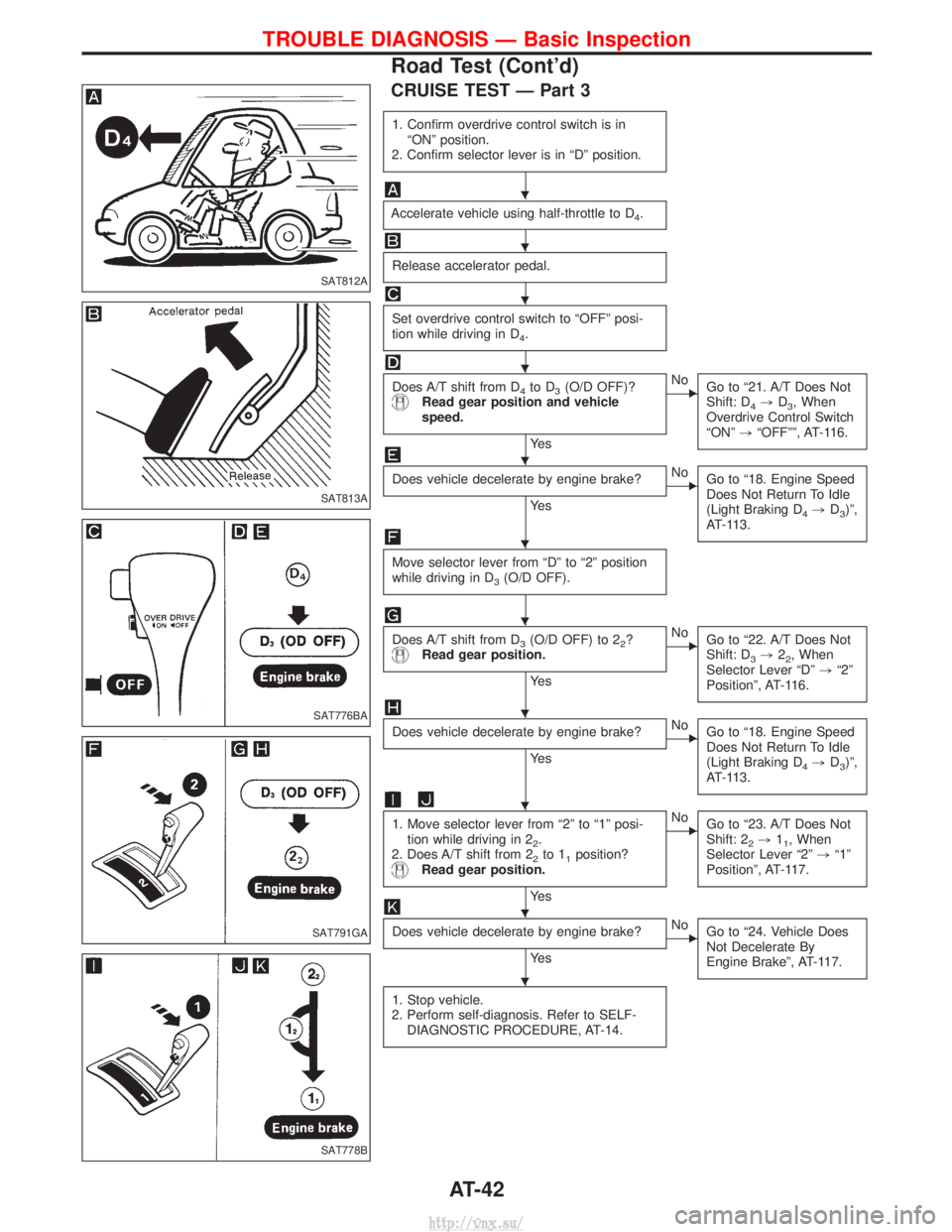
CRUISE TEST Ð Part 3
1. Confirm overdrive control switch is inªONº position.
2. Confirm selector lever is in ªDº position.
Accelerate vehicle using half-throttle to D4.
Release accelerator pedal.
Set overdrive control switch to ªOFFº posi-
tion while driving in D
4.
Does A/T shift from D4to D3(O/D OFF)?Read gear position and vehicle
speed.
Ye s
ENo Go to ª21. A/T Does Not
Shift: D
4,D3, When
Overdrive Control Switch
ªONº ,ªOFFºº, AT-116.
Does vehicle decelerate by engine brake?
Ye s
ENo
Go to ª18. Engine Speed
Does Not Return To Idle
(Light Braking D
4,D3)º,
AT-113.
Move selector lever from ªDº to ª2º position
while driving in D
3(O/D OFF).
Does A/T shift from D3(O/D OFF) to 22?Read gear position.
Ye s
ENo Go to ª22. A/T Does Not
Shift: D
3,22, When
Selector Lever ªDº ,ª2º
Positionº, AT-116.
Does vehicle decelerate by engine brake?
Ye s
ENo Go to ª18. Engine Speed
Does Not Return To Idle
(Light Braking D
4,D3)º,
AT-113.
1. Move selector lever from ª2º to ª1º posi- tion while driving in 2
2.
2. Does A/T shift from 2
2to 11position?Read gear position.
Ye s
ENo Go to ª23. A/T Does Not
Shift: 2
2,11, When
Selector Lever ª2º ,ª1º
Positionº, AT-117.
Does vehicle decelerate by engine brake?
Ye s
ENo Go to ª24. Vehicle Does
Not Decelerate By
Engine Brakeº, AT-117.
1. Stop vehicle.
2. Perform self-diagnosis. Refer to SELF- DIAGNOSTIC PROCEDURE, AT-14.
SAT812A
SAT813A
SAT776BA
SAT791GA
SAT778B
H
H
H
H
H
H
H
H
H
H
H
TROUBLE DIAGNOSIS Ð Basic Inspection
Road Test (Cont'd)
AT-42
http://vnx.su/
Page 926 of 1833
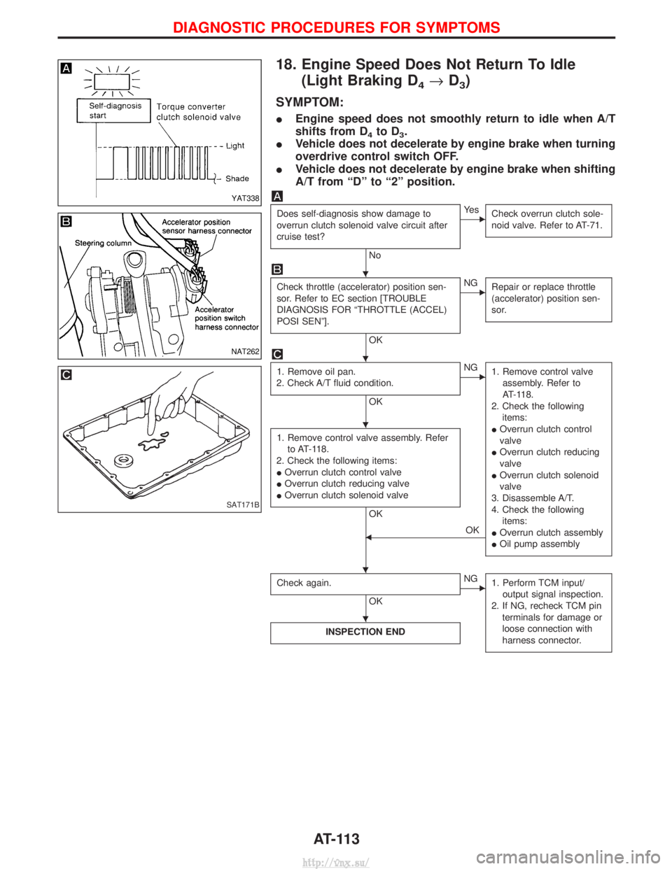
18. Engine Speed Does Not Return To Idle(Light Braking D
4®D3)
SYMPTOM:
I Engine speed does not smoothly return to idle when A/T
shifts from D
4to D3.
I Vehicle does not decelerate by engine brake when turning
overdrive control switch OFF.
I Vehicle does not decelerate by engine brake when shifting
A/T from ªDº to ª2º position.
Does self-diagnosis show damage to
overrun clutch solenoid valve circuit after
cruise test?
No
EYe s
Check overrun clutch sole-
noid valve. Refer to AT-71.
Check throttle (accelerator) position sen-
sor. Refer to EC section [TROUBLE
DIAGNOSIS FOR ªTHROTTLE (ACCEL)
POSI SENº].
OK
ENGRepair or replace throttle
(accelerator) position sen-
sor.
1. Remove oil pan.
2. Check A/T fluid condition.
OK
ENG 1. Remove control valve
assembly. Refer to
AT-118.
2. Check the following items:
I Overrun clutch control
valve
I Overrun clutch reducing
valve
I Overrun clutch solenoid
valve
3. Disassemble A/T.
4. Check the following items:
I Overrun clutch assembly
I Oil pump assembly
1. Remove control valve assembly. Refer
to AT-118.
2. Check the following items:
I Overrun clutch control valve
I Overrun clutch reducing valve
I Overrun clutch solenoid valve
OK
FOK
Check again.
OK
ENG 1. Perform TCM input/
output signal inspection.
2. If NG, recheck TCM pin terminals for damage or
loose connection with
harness connector.
INSPECTION END
YAT338
NAT262
SAT171B
H
H
H
HH
H
DIAGNOSTIC PROCEDURES FOR SYMPTOMS
AT-113
http://vnx.su/