window NISSAN TERRANO 2004 Service Repair Manual
[x] Cancel search | Manufacturer: NISSAN, Model Year: 2004, Model line: TERRANO, Model: NISSAN TERRANO 2004Pages: 1833, PDF Size: 53.42 MB
Page 44 of 1833
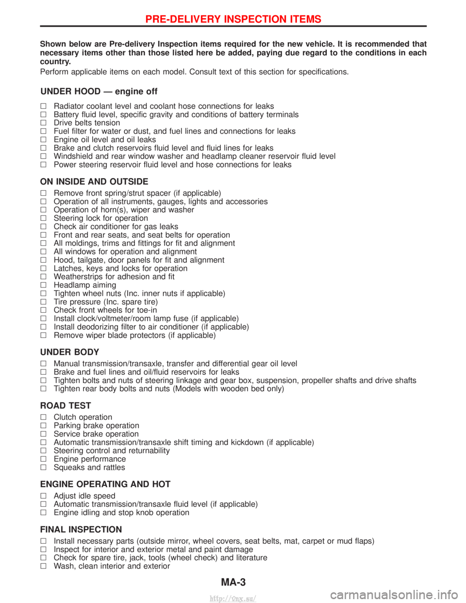
Shown below are Pre-delivery Inspection items required for the new vehicle. It is recommended that
necessary items other than those listed here be added, paying due regard to the conditions in each
country.
Perform applicable items on each model. Consult text of this section for specifications.
UNDER HOOD Ð engine off
lRadiator coolant level and coolant hose connections for leaks
l Battery fluid level, specific gravity and conditions of battery terminals
l Drive belts tension
l Fuel filter for water or dust, and fuel lines and connections for leaks
l Engine oil level and oil leaks
l Brake and clutch reservoirs fluid level and fluid lines for leaks
l Windshield and rear window washer and headlamp cleaner reservoir fluid level
l Power steering reservoir fluid level and hose connections for leaks
ON INSIDE AND OUTSIDE
lRemove front spring/strut spacer (if applicable)
l Operation of all instruments, gauges, lights and accessories
l Operation of horn(s), wiper and washer
l Steering lock for operation
l Check air conditioner for gas leaks
l Front and rear seats, and seat belts for operation
l All moldings, trims and fittings for fit and alignment
l All windows for operation and alignment
l Hood, tailgate, door panels for fit and alignment
l Latches, keys and locks for operation
l Weatherstrips for adhesion and fit
l Headlamp aiming
l Tighten wheel nuts (Inc. inner nuts if applicable)
l Tire pressure (Inc. spare tire)
l Check front wheels for toe-in
l Install clock/voltmeter/room lamp fuse (if applicable)
l Install deodorizing filter to air conditioner (if applicable)
l Remove wiper blade protectors (if applicable)
UNDER BODY
lManual transmission/transaxle, transfer and differential gear oil level
l Brake and fuel lines and oil/fluid reservoirs for leaks
l Tighten bolts and nuts of steering linkage and gear box, suspension, propeller shafts and drive shafts
l Tighten rear body bolts and nuts (Models with wooden bed only)
ROAD TEST
lClutch operation
l Parking brake operation
l Service brake operation
l Automatic transmission/transaxle shift timing and kickdown (if applicable)
l Steering control and returnability
l Engine performance
l Squeaks and rattles
ENGINE OPERATING AND HOT
lAdjust idle speed
l Automatic transmission/transaxle fluid level (if applicable)
l Engine idling and stop knob operation
FINAL INSPECTION
lInstall necessary parts (outside mirror, wheel covers, seat belts, mat, carpet or mud flaps)
l Inspect for interior and exterior metal and paint damage
l Check for spare tire, jack, tools (wheel check) and literature
l Wash, clean interior and exterior
PRE-DELIVERY INSPECTION ITEMS
MA-3
http://vnx.su/
Page 1338 of 1833
BODY & TRIM
SECTION
BT
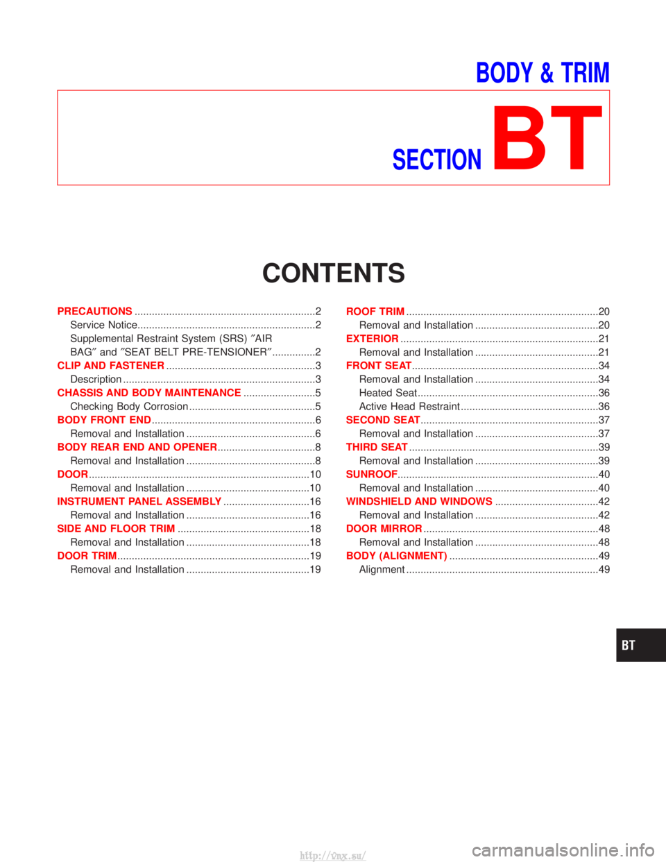
CONTENTS
PRECAUTIONS ...............................................................2
Service Notice..............................................................2
Supplemental Restraint System (SRS) ²AIR
BAG² and²SEAT BELT PRE-TENSIONER² ...............2
CLIP AND FASTENER ....................................................3
Description ...................................................................3
CHASSIS AND BODY MAINTENANCE .........................5
Checking Body Corrosion ............................................5
BODY FRONT END .........................................................6
Removal and Installation .............................................6
BODY REAR END AND OPENER ..................................8
Removal and Installation .............................................8
DOOR ........................................................................\
.....10
Removal and Installation ...........................................10
INSTRUMENT PANEL ASSEMBLY ..............................16
Removal and Installation ...........................................16
SIDE AND FLOOR TRIM ..............................................18
Removal and Installation ...........................................18
DOOR TRIM ...................................................................19
Removal and Installation ...........................................19 ROOF TRIM
...................................................................20
Removal and Installation ...........................................20
EXTERIOR .....................................................................21
Removal and Installation ...........................................21
FRONT SEAT .................................................................34
Removal and Installation ...........................................34
Heated Seat ...............................................................36
Active Head Restraint ................................................36
SECOND SEAT ..............................................................37
Removal and Installation ...........................................37
THIRD SEAT ..................................................................39
Removal and Installation ...........................................39
SUNROOF ......................................................................40
Removal and Installation ...........................................40
WINDSHIELD AND WINDOWS ....................................42
Removal and Installation ...........................................42
DOOR MIRROR .............................................................48
Removal and Installation ...........................................48
BODY (ALIGNMENT) ....................................................49
Alignment ...................................................................49
http://vnx.su/
Page 1379 of 1833
Removal and Installation
REMOVAL
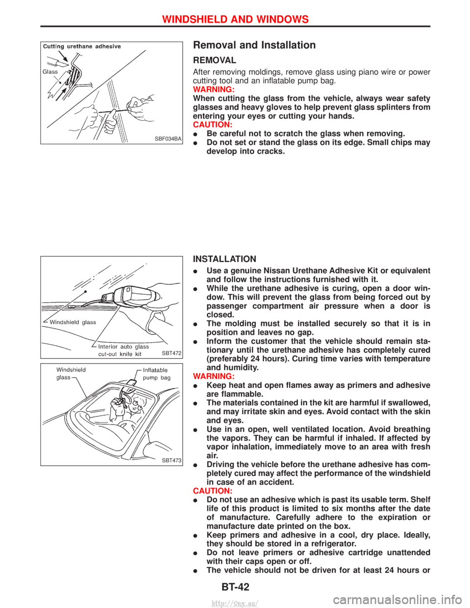
After removing moldings, remove glass using piano wire or power
cutting tool and an inflatable pump bag.
WARNING:
When cutting the glass from the vehicle, always wear safety
glasses and heavy gloves to help prevent glass splinters from
entering your eyes or cutting your hands.
CAUTION:
IBe careful not to scratch the glass when removing.
I Do not set or stand the glass on its edge. Small chips may
develop into cracks.
INSTALLATION
IUse a genuine Nissan Urethane Adhesive Kit or equivalent
and follow the instructions furnished with it.
I While the urethane adhesive is curing, open a door win-
dow. This will prevent the glass from being forced out by
passenger compartment air pressure when a door is
closed.
I The molding must be installed securely so that it is in
position and leaves no gap.
I Inform the customer that the vehicle should remain sta-
tionary until the urethane adhesive has completely cured
(preferably 24 hours). Curing time varies with temperature
and humidity.
WARNING:
I Keep heat and open flames away as primers and adhesive
are flammable.
I The materials contained in the kit are harmful if swallowed,
and may irritate skin and eyes. Avoid contact with the skin
and eyes.
I Use in an open, well ventilated location. Avoid breathing
the vapors. They can be harmful if inhaled. If affected by
vapor inhalation, immediately move to an area with fresh
air.
I Driving the vehicle before the urethane adhesive has com-
pletely cured may affect the performance of the windshield
in case of an accident.
CAUTION:
I Do not use an adhesive which is past its usable term. Shelf
life of this product is limited to six months after the date
of manufacture. Carefully adhere to the expiration or
manufacture date printed on the box.
I Keep primers and adhesive in a cool, dry place. Ideally,
they should be stored in a refrigerator.
I Do not leave primers or adhesive cartridge unattended
with their caps open or off.
I The vehicle should not be driven for at least 24 hours or
SBF034BA
SBT472
SBT473
WINDSHIELD AND WINDOWS
BT-42
http://vnx.su/
Page 1380 of 1833
until the urethane adhesive has completely cured. Curing
time varies depending on temperature and humidities. The
curing time will increase under higher temperatures and
lower humidities.
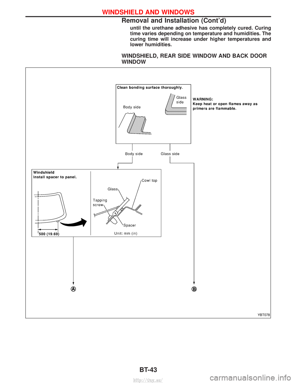
WINDSHIELD, REAR SIDE WINDOW AND BACK DOOR
WINDOW
YBT078
WINDSHIELD AND WINDOWS
Removal and Installation (Cont'd)BT-43
http://vnx.su/
Page 1381 of 1833
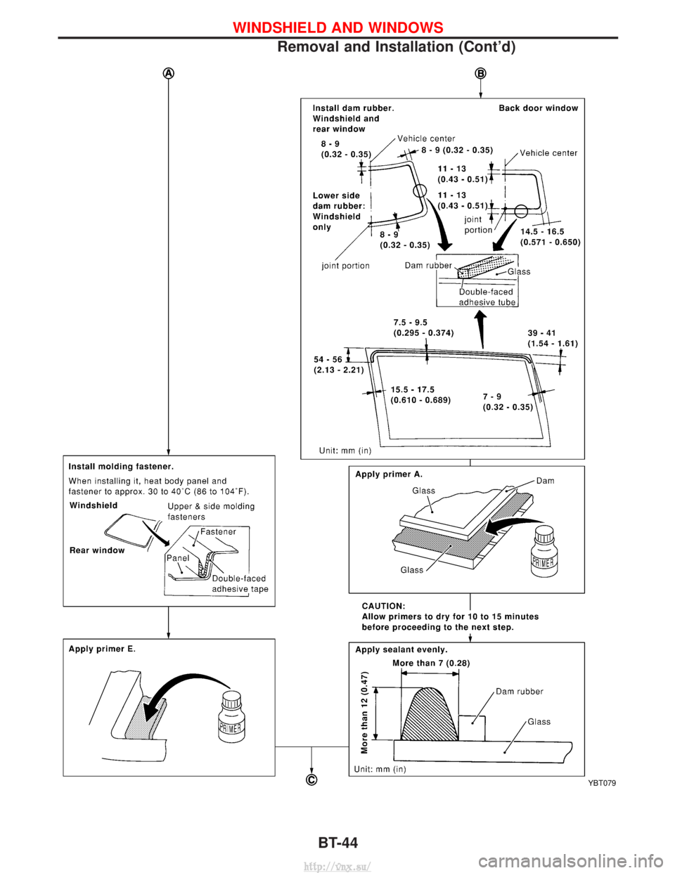
YBT079
WINDSHIELD AND WINDOWS
Removal and Installation (Cont'd)BT-44
http://vnx.su/
Page 1382 of 1833
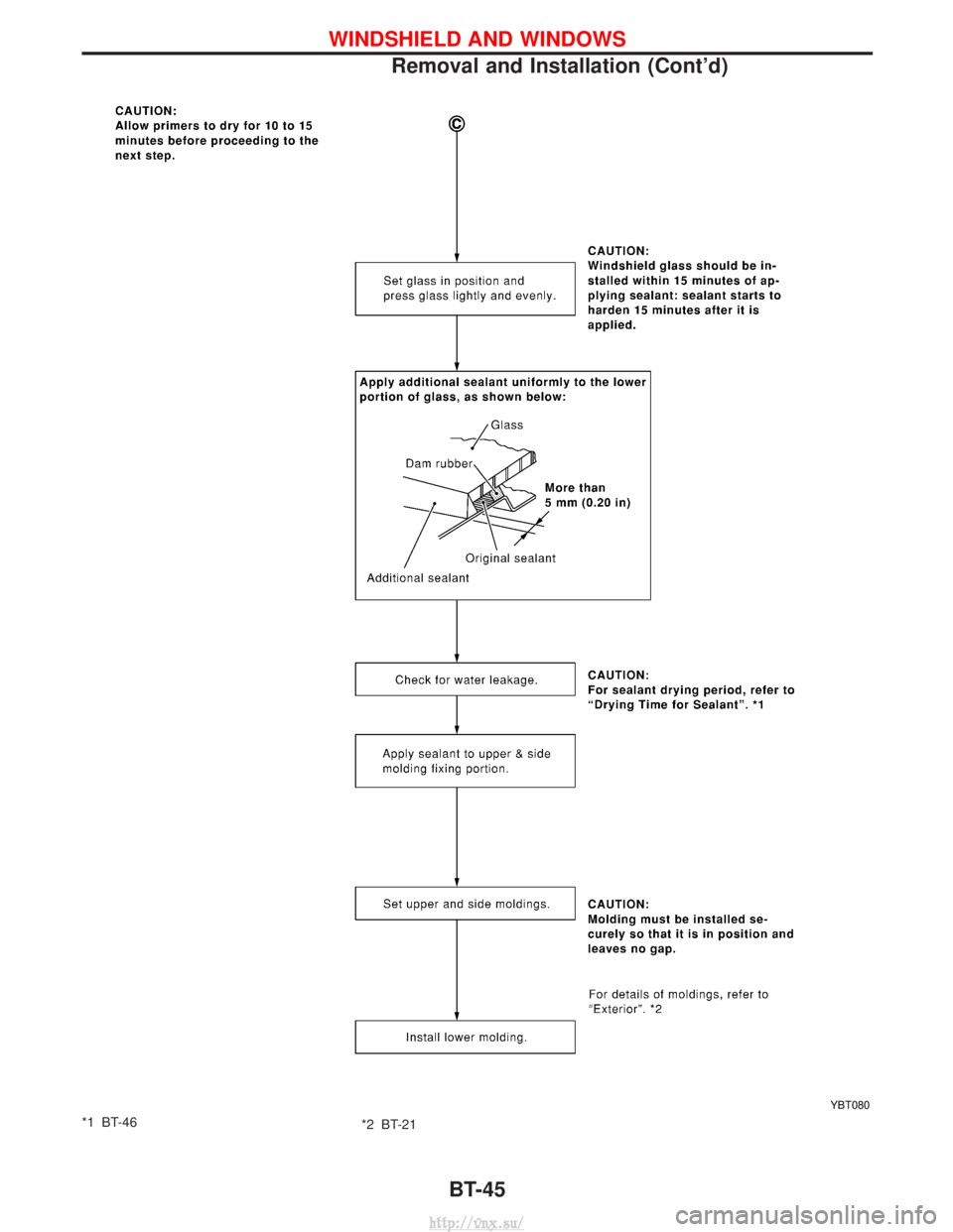
*1 BT-46*2 BT-21
YBT080
WINDSHIELD AND WINDOWS
Removal and Installation (Cont'd)
BT-45
http://vnx.su/
Page 1383 of 1833
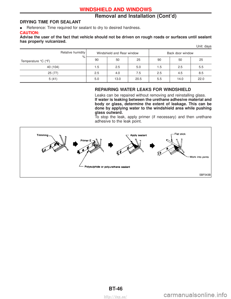
DRYING TIME FOR SEALANT
IReference: Time required for sealant to dry to desired hardness.
CAUTION:
Advise the user of the fact that vehicle should not be driven on rough roads or surfaces until sealant
has properly vulcanized.
Unit: days
Relative humidity
%
Temperature ÉC (ÉF) Windshield and Rear window
Back door window
90 5025905025
40 (104) 1.52.55.01.52.55.5
25 (77) 2.54.07.52.54.58.5
5 (41) 5.0 13.0 20.5 5.5 14.0 22.0
REPAIRING WATER LEAKS FOR WINDSHIELD
Leaks can be repaired without removing and reinstalling glass.
If water is leaking between the urethane adhesive material and
body or glass, determine the extent of leakage. This can be
done by applying water to the windshield area while pushing
glass outward.
To stop the leak, apply primer (if necessary) and then urethane
adhesive to the leak point.
SBF543B
WINDSHIELD AND WINDOWS
Removal and Installation (Cont'd)
BT-46
http://vnx.su/
Page 1384 of 1833
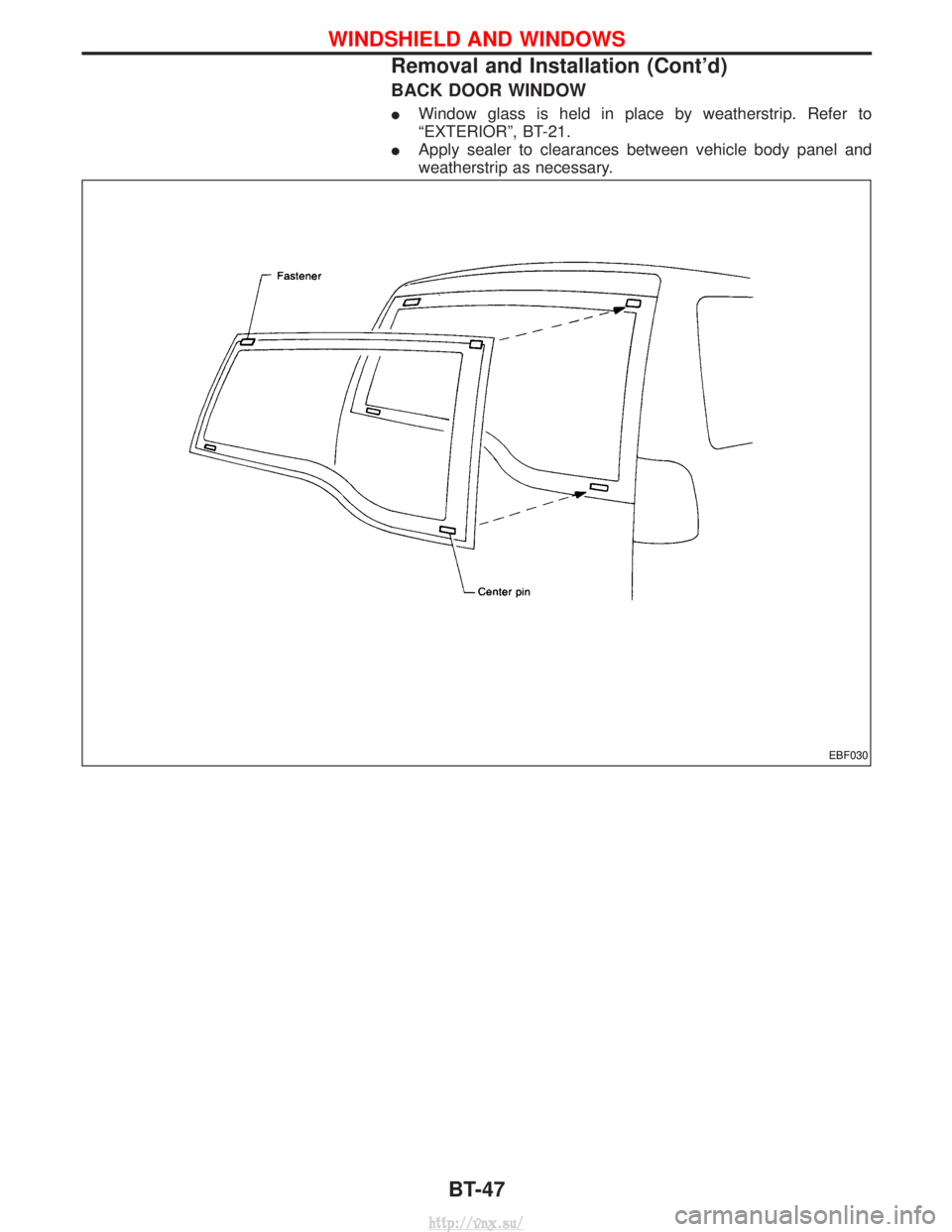
BACK DOOR WINDOW
IWindow glass is held in place by weatherstrip. Refer to
ªEXTERIORº, BT-21.
I Apply sealer to clearances between vehicle body panel and
weatherstrip as necessary.
EBF030
WINDSHIELD AND WINDOWS
Removal and Installation (Cont'd)
BT-47
http://vnx.su/
Page 1428 of 1833
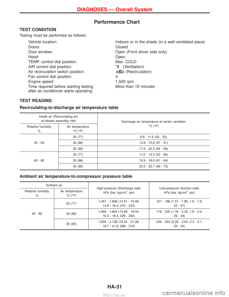
Performance Chart
TEST CONDITION
Testing must be performed as follows:
Vehicle location:Indoors or in the shade (in a well-ventilated place)
Doors: Closed
Door window: Open (Front driver side only)
Hood: Open
TEMP. control dial position: Max. COLD
AIR control dial position:
(Ventilation)
Air recirculation switch position:
(Recirculation)
Fan control dial position: 4
Engine speed: 1,500 rpm
Time required before starting testing
after air conditioner starts operating: More than 10 minutes
TEST READING
Recirculating-to-discharge air temperature table
Inside air (Recirculating air)
at blower assembly inlet Discharge air temperature at center ventilator
ÉC (ÉF)
Relative humidity
% Air temperature
ÉC (ÉF)
40-60 25 (77) 9.8 - 11.5 (50 - 53)
30 (86) 13.8 - 15.9 (57 - 61)
35 (95) 17.9 - 20.3 (64 - 69)
60-80 25 (77) 11.5 - 13.3 (53 - 56)
30 (86) 15.9 - 18.0 (61 - 64)
35 (95) 20.3 - 22.7 (69 - 73)
Ambient air temperature-to-compressor pressure table
Ambient air
High-pressure (Discharge side)
kPa (bar, kg/cm
2, psi) Low-pressure (Suction side)
kPa (bar, kg/cm2, psi)
Relative humidity
% Air temperature
ÉC (ÉF)
40-80 25 (77)
1,451 - 1,608 (14.51 - 16.08,
14.8 - 16.4, 210 - 233) 157 - 186 (1.57 - 1.86, 1.6 - 1.9,
23 - 27)
30 (86) 1,569 - 1,804 (15.69 - 18.04,
16.0 - 18.4, 228 - 262) 176 - 235 (1.76 - 2.35, 1.8 - 2.4,
26 - 34)
35 (95) 1,834 - 2,138 (18.34 - 21.38,
18.7 - 21.8, 266 - 310) 226 - 304 (2.26 - 3.04, 2.3 - 3.1,
33 - 44)
DIAGNOSES Ð Overall System
HA-31
http://vnx.su/
Page 1495 of 1833
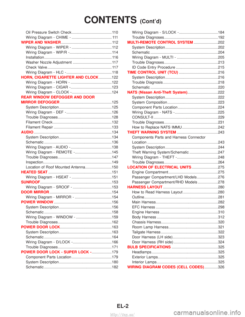
Oil Pressure Switch Check ...................................... 110
Wiring Diagram - CHIME - ...................................... 111
WIPER AND WASHER ................................................ 112
Wiring Diagram - WIPER - ...................................... 112
Wiring Diagram - WIP/R -........................................ 114
Installation ................................................................ 116
Washer Nozzle Adjustment ..................................... 117
Check Valve ............................................................. 117
Wiring Diagram - HLC - ........................................... 118
HORN, CIGARETTE LIGHTER AND CLOCK ............122
Wiring Diagram - HORN - .......................................122
Wiring Diagram - CIGAR -.......................................123
Wiring Diagram - CLOCK -......................................124
REAR WINDOW DEFOGGER AND DOOR
MIRROR DEFOGGER .................................................125
System Description ..................................................125
Wiring Diagram - DEF - ...........................................126
Trouble Diagnoses...................................................128
Filament Check ........................................................132
Filament Repair .......................................................133
AUDIO ........................................................................\
..134
System Description ..................................................134
Schematic ................................................................136
Wiring Diagram - AUDIO - .......................................138
Wiring Diagram - REMOTE -...................................145
Trouble Diagnoses...................................................147
Inspection.................................................................149
Location of Roof Mounted Antenna .........................150
HEATED SEAT ............................................................151
Wiring Diagram - HSEAT - ......................................151
SUNROOF ....................................................................153
Wiring Diagram - SROOF - .....................................153
DOOR MIRROR ...........................................................154
Wiring Diagram - MIRROR - ...................................154
POWER WINDOW .......................................................156
System Description ..................................................156
Schematic ................................................................158
Wiring Diagram - WINDOW - ..................................159
Trouble Diagnoses...................................................162
POWER DOOR LOCK .................................................163
System Description ..................................................163
Schematic ................................................................164
Wiring Diagram - D/LOCK -.....................................166
Trouble Diagnoses...................................................171
POWER DOOR LOCK - SUPER LOCK - ...................179
Component Parts Location ......................................179
System Description ..................................................180
Schematic ................................................................182 Wiring Diagram - S/LOCK - .....................................184
Trouble Diagnoses...................................................192
MULTI-REMOTE CONTROL SYSTEM .......................202
System Description ..................................................202
Schematic ................................................................204
Wiring Diagram - MULTI - .......................................205
Trouble Diagnoses...................................................213
ID Code Entry Procedure ........................................215
TIME CONTROL UNIT (TCU) .....................................216
System Description ..................................................216
Trouble Diagnosis ....................................................218
Schematic ................................................................220
NATS (Nissan Anti-Theft System) .............................222
System Description ..................................................222
System Composition ................................................223
Component Parts Location ......................................224
Wiring Diagram - NATS -.........................................225
CONSULT-II .............................................................229
Trouble Diagnoses...................................................231
How to Replace NATS IMMU ..................................242
THEFT WARNING SYSTEM .......................................243
Components Parts and Harness Connector
Location ...................................................................243
System Description ..................................................244
Theft Warning System/Schematic ...........................247
Wiring Diagram - THEFT -.......................................248
Trouble Diagnoses...................................................264
LOCATION OF ELECTRICAL UNITS .........................275
Engine Compartment ...............................................275
Passenger Compartment/LHD Models ....................276
Passenger Compartment/RHD Models ...................278
HARNESS LAYOUT ....................................................280
How to Read Harness Layout .................................280
Outline......................................................................281
Main Harness...........................................................282
EFC Harness ...........................................................298
Engine Harness .......................................................310
Body Harness ..........................................................312
Chassis Harness......................................................320
Room Lamp Harness...............................................321
Tailgate Harness ......................................................322
Door Harness (LH side)...........................................323
Door Harness (RH side) ..........................................324
BULB SPECIFICATIONS ............................................325
Headlamps ...............................................................325
Exterior Lamps.........................................................325
Interior Lamps ..........................................................325
WIRING DIAGRAM CODES (CELL CODES) .............326
CONTENTS(Cont'd)
EL-2
http://vnx.su/