height NISSAN TERRANO 2004 Service Repair Manual
[x] Cancel search | Manufacturer: NISSAN, Model Year: 2004, Model line: TERRANO, Model: NISSAN TERRANO 2004Pages: 1833, PDF Size: 53.42 MB
Page 33 of 1833
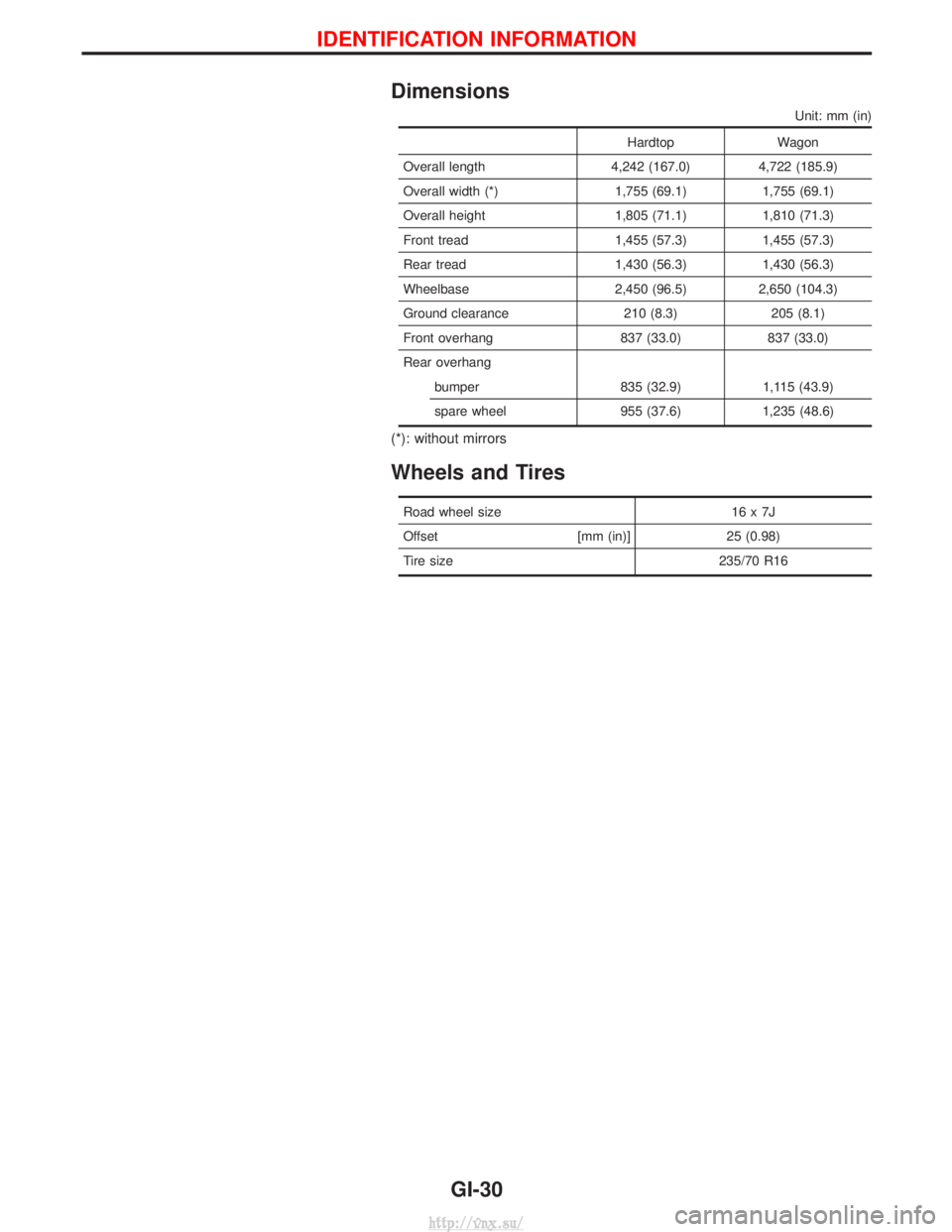
Dimensions
Unit: mm (in)
HardtopWagon
Overall length 4,242 (167.0) 4,722 (185.9)
Overall width (*) 1,755 (69.1) 1,755 (69.1)
Overall height 1,805 (71.1) 1,810 (71.3)
Front tread 1,455 (57.3) 1,455 (57.3)
Rear tread 1,430 (56.3) 1,430 (56.3)
Wheelbase 2,450 (96.5) 2,650 (104.3)
Ground clearance 210 (8.3) 205 (8.1)
Front overhang 837 (33.0) 837 (33.0)
Rear overhang bumper 835 (32.9) 1,115 (43.9)
spare wheel 955 (37.6) 1,235 (48.6)
(*): without mirrors
Wheels and Tires
Road wheel size 16 x 7J
Offset [mm (in)]25 (0.98)
Tire size 235/70 R16
IDENTIFICATION INFORMATION
GI-30
http://vnx.su/
Page 77 of 1833
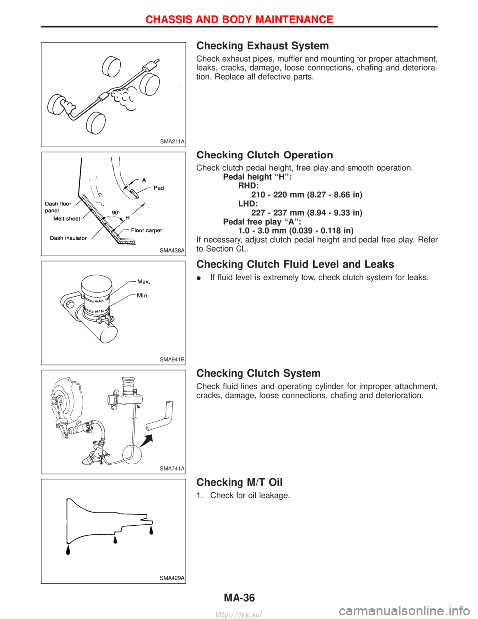
Checking Exhaust System
Check exhaust pipes, muffler and mounting for proper attachment,
leaks, cracks, damage, loose connections, chafing and deteriora-
tion. Replace all defective parts.
Checking Clutch Operation
Check clutch pedal height, free play and smooth operation.Pedal height ªHº:RHD:210 - 220 mm (8.27 - 8.66 in)
LHD: 227 - 237 mm (8.94 - 9.33 in)
Pedal free play ªAº: 1.0 - 3.0 mm (0.039 - 0.118 in)
If necessary, adjust clutch pedal height and pedal free play. Refer
to Section CL.
Checking Clutch Fluid Level and Leaks
I If fluid level is extremely low, check clutch system for leaks.
Checking Clutch System
Check fluid lines and operating cylinder for improper attachment,
cracks, damage, loose connections, chafing and deterioration.
Checking M/T Oil
1. Check for oil leakage.
SMA211A
SMA438A
SMA941B
SMA741A
SMA429A
CHASSIS AND BODY MAINTENANCE
MA-36
http://vnx.su/
Page 83 of 1833
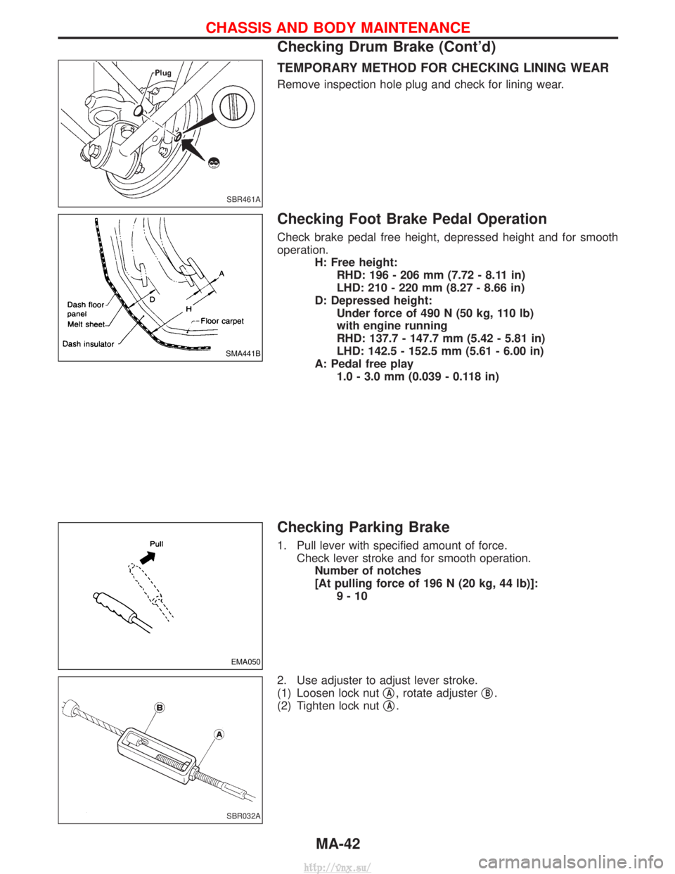
TEMPORARY METHOD FOR CHECKING LINING WEAR
Remove inspection hole plug and check for lining wear.
Checking Foot Brake Pedal Operation
Check brake pedal free height, depressed height and for smooth
operation.H: Free height:RHD: 196 - 206 mm (7.72 - 8.11 in)
LHD: 210 - 220 mm (8.27 - 8.66 in)
D: Depressed height: Under force of 490 N (50 kg, 110 lb)
with engine running
RHD: 137.7 - 147.7 mm (5.42 - 5.81 in)
LHD: 142.5 - 152.5 mm (5.61 - 6.00 in)
A: Pedal free play 1.0 - 3.0 mm (0.039 - 0.118 in)
Checking Parking Brake
1. Pull lever with specified amount of force.Check lever stroke and for smooth operation.Number of notches
[At pulling force of 196 N (20 kg, 44 lb)]: 9-10
2. Use adjuster to adjust lever stroke.
(1) Loosen lock nut q
A, rotate adjusterqB.
(2) Tighten lock nut q
A.
SBR461A
SMA441B
EMA050
SBR032A
CHASSIS AND BODY MAINTENANCE
Checking Drum Brake (Cont'd)
MA-42
http://vnx.su/
Page 90 of 1833
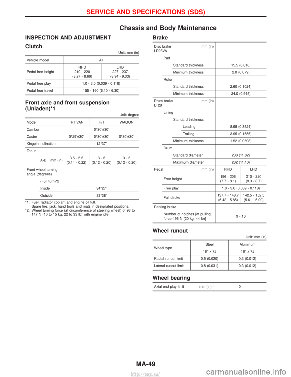
Chassis and Body Maintenance
INSPECTION AND ADJUSTMENT
Clutch
Unit: mm (in)
Vehicle modelAll
Pedal free height RHD
210 - 220
(8.27 - 8.66) LHD
227 - 237
(8.94 - 9.33)
Pedal free play 1.0 - 3.0 (0.039 - 0.118)
Pedal free travel 155 - 160 (6.10 - 6.30)
Front axle and front suspension
(Unladen)*1
Unit: degree
Model H/T VAN H/T WAGON
Camber 0É30¢ 30¢
Caster 0É29¢ 30¢ 0É30¢ 30¢ 0É30¢ 30¢
Kingpin inclination 12É37¢
Toe-in
A-B mm (in) 3.5 - 5.5
(0.14 - 0.22) 3-5
(0.12 - 0.20) 3-5
(0.12 - 0.20)
Front wheel turning
angle (degrees) (Full turn)*2
Inside 34É27¢
Outside 33É38¢
*1: Fuel, radiator coolant and engine oil full. Spare tire, jack, hand tools and mats in designated positions.
*2: Wheel turning force (at circumference of steering wheel) of 98 to 147 N (10 to 15 kg, 22 to 33 lb) with engine idle.
Brake
Disc brake mm (in)
LD28VA
PadStandard thickness 15.5 (0.610)
Minimum thickness 2.0 (0.079)
Rotor Standard thickness 2.60 (0.1024)
Minimum thickness 24.0 (0.945)
Drum brake mm (in)
LT28 LiningStandard thicknessLeading 8.95 (0.3524)
Trailing 3.95 (0.1555)
Minimum thickness 1.52 (0.0598)
Drum Standard diameter 280 (11.02)
Maximum diameter 282 (11.10)
Pedal mm (in) RHD LHD
Free height 196 - 206
(7.7 - 8.1) 210 - 220
(8.3 - 8.7)
Free play 1.0 - 3.0 (0.039 - 0.118)
Full stroke 137.7 - 148.7
(5.42 - 5.85) 142.5 - 152.5
(5.61 - 6.00)
Parking brake Number of notches [at pulling
force 196 N (20 kg, 44 lb)] 9-10
Wheel runout
Unit: mm (in)
Wheel typeSteel Aluminum
16² x7J 16 ²x7J
Radial runout limit 0.5 (0.020) 0.3 (0.012)
Lateral runout limit 0.8 (0.031) 0.3 (0.012)
Wheel bearing
Axial end play limit mm (in) 0
SERVICE AND SPECIFICATIONS (SDS)
MA-49
http://vnx.su/
Page 122 of 1833
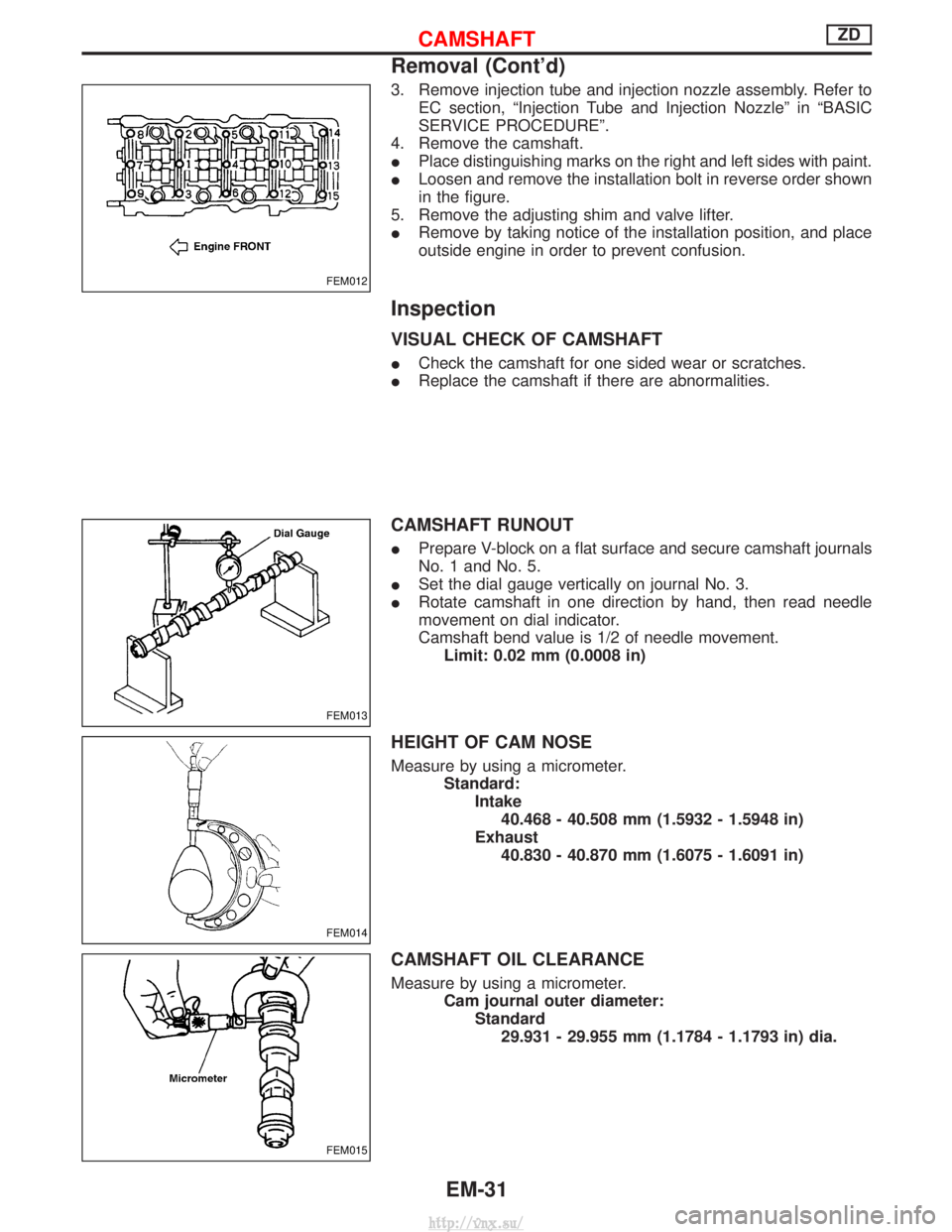
3. Remove injection tube and injection nozzle assembly. Refer toEC section, ªInjection Tube and Injection Nozzleº in ªBASIC
SERVICE PROCEDUREº.
4. Remove the camshaft.
I Place distinguishing marks on the right and left sides with paint.
I Loosen and remove the installation bolt in reverse order shown
in the figure.
5. Remove the adjusting shim and valve lifter.
I Remove by taking notice of the installation position, and place
outside engine in order to prevent confusion.
Inspection
VISUAL CHECK OF CAMSHAFT
ICheck the camshaft for one sided wear or scratches.
I Replace the camshaft if there are abnormalities.
CAMSHAFT RUNOUT
IPrepare V-block on a flat surface and secure camshaft journals
No. 1 and No. 5.
I Set the dial gauge vertically on journal No. 3.
I Rotate camshaft in one direction by hand, then read needle
movement on dial indicator.
Camshaft bend value is 1/2 of needle movement.
Limit: 0.02 mm (0.0008 in)
HEIGHT OF CAM NOSE
Measure by using a micrometer. Standard:Intake40.468 - 40.508 mm (1.5932 - 1.5948 in)
Exhaust 40.830 - 40.870 mm (1.6075 - 1.6091 in)
CAMSHAFT OIL CLEARANCE
Measure by using a micrometer. Cam journal outer diameter:Standard29.931 - 29.955 mm (1.1784 - 1.1793 in) dia.
FEM012
FEM013
FEM014
FEM015
CAMSHAFTZD
Removal (Cont'd)
EM-31
http://vnx.su/
Page 144 of 1833
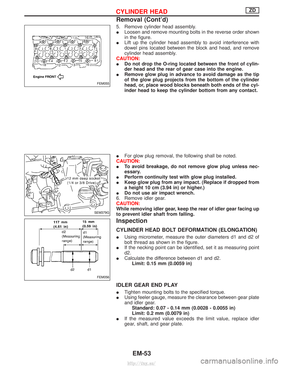
5. Remove cylinder head assembly.
ILoosen and remove mounting bolts in the reverse order shown
in the figure.
I Lift up the cylinder head assembly to avoid interference with
dowel pins located between the block and head, and remove
cylinder head assembly.
CAUTION:
I Do not drop the O-ring located between the front of cylin-
der head and the rear of gear case into the engine.
I Remove glow plug in advance to avoid damage as the tip
of the glow plug projects from the bottom of the cylinder
head, or, place wood blocks beneath both ends of the cyl-
inder head to keep the cylinder bottom from any contact.
I For glow plug removal, the following shall be noted.
CAUTION:
I To avoid breakage, do not remove glow plug unless nec-
essary.
I Perform continuity test with glow plug installed.
I Keep glow plug from any impact. (Replace if dropped from
a height 10 cm (3.94 in) or higher.)
I Do not use air impact wrench.
6. Remove idler gear.
CAUTION:
While removing idler gear, keep the rear of idler gear facing up
to prevent idler shaft from falling.
Inspection
CYLINDER HEAD BOLT DEFORMATION (ELONGATION)
I Using micrometer, measure the outer diameters d1 and d2 of
bolt thread as shown in the figure.
I If the necking point can be identified, set it as measuring point
d2.
I Calculate the difference between d1 and d2.
Limit: 0.15 mm (0.0059 in)
IDLER GEAR END PLAY
I Tighten mounting bolts to the specified torque.
I Using feeler gauge, measure the clearance between gear plate
and idler gear.
Standard: 0.07 - 0.14 mm (0.0028 - 0.0055 in)
Limit: 0.2 mm (0.0079 in)
I If the measured value exceeds the limit value, replace idler
gear, shaft, and gear plate.
FEM055
SEM379G
FEM056
CYLINDER HEADZD
Removal (Cont'd)
EM-53
http://vnx.su/
Page 145 of 1833
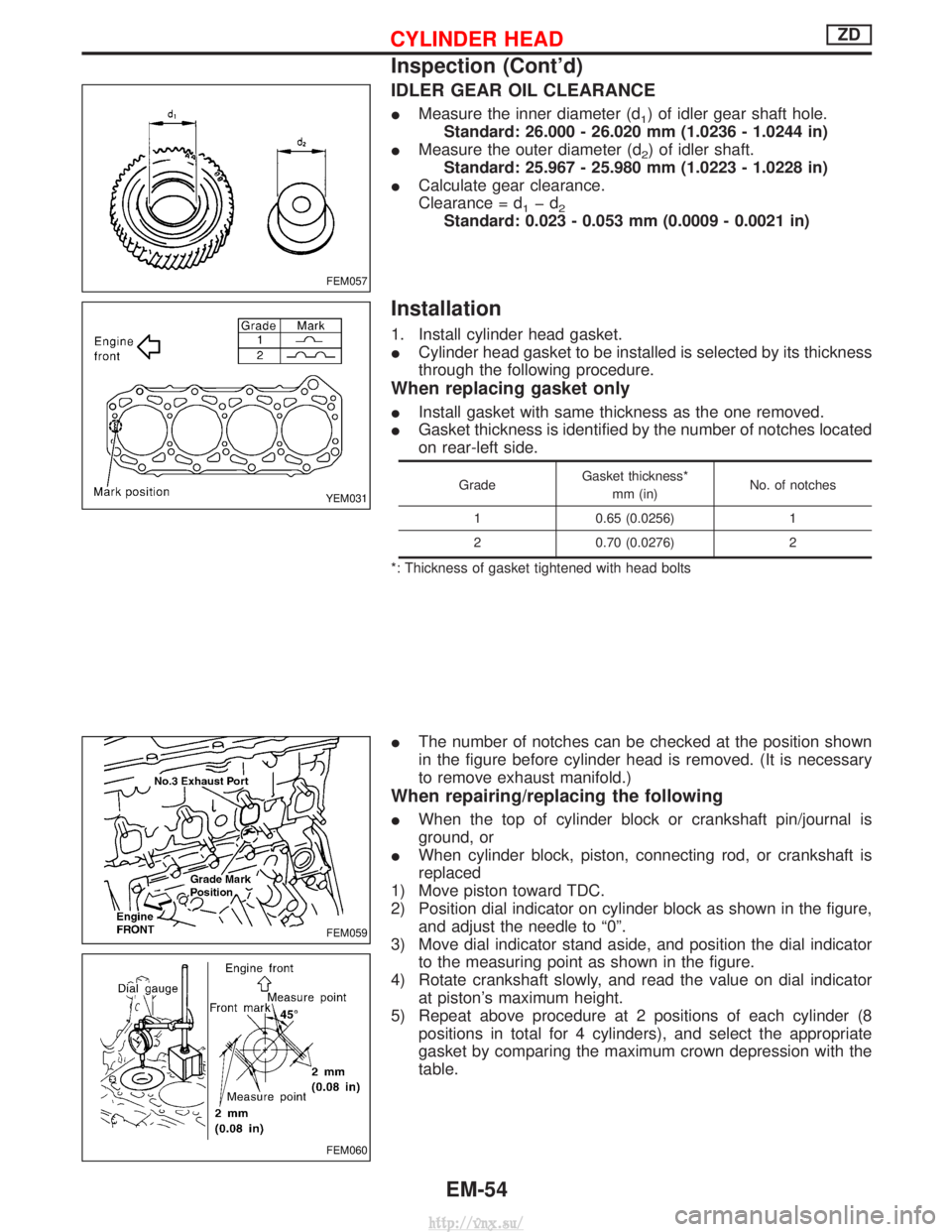
IDLER GEAR OIL CLEARANCE
IMeasure the inner diameter (d1) of idler gear shaft hole.
Standard: 26.000 - 26.020 mm (1.0236 - 1.0244 in)
I Measure the outer diameter (d
2) of idler shaft.
Standard: 25.967 - 25.980 mm (1.0223 - 1.0228 in)
I Calculate gear clearance.
Clearance = d
1þd2Standard: 0.023 - 0.053 mm (0.0009 - 0.0021 in)
Installation
1. Install cylinder head gasket.
ICylinder head gasket to be installed is selected by its thickness
through the following procedure.
When replacing gasket only
IInstall gasket with same thickness as the one removed.
I Gasket thickness is identified by the number of notches located
on rear-left side.
Grade Gasket thickness*
mm (in) No. of notches
1 0.65 (0.0256) 1
2 0.70 (0.0276) 2
*: Thickness of gasket tightened with head bolts
I The number of notches can be checked at the position shown
in the figure before cylinder head is removed. (It is necessary
to remove exhaust manifold.)
When repairing/replacing the following
IWhen the top of cylinder block or crankshaft pin/journal is
ground, or
I When cylinder block, piston, connecting rod, or crankshaft is
replaced
1) Move piston toward TDC.
2) Position dial indicator on cylinder block as shown in the figure, and adjust the needle to ª0º.
3) Move dial indicator stand aside, and position the dial indicator to the measuring point as shown in the figure.
4) Rotate crankshaft slowly, and read the value on dial indicator at piston's maximum height.
5) Repeat above procedure at 2 positions of each cylinder (8 positions in total for 4 cylinders), and select the appropriate
gasket by comparing the maximum crown depression with the
table.
FEM057
YEM031
FEM059
FEM060
CYLINDER HEADZD
Inspection (Cont'd)
EM-54
http://vnx.su/
Page 152 of 1833
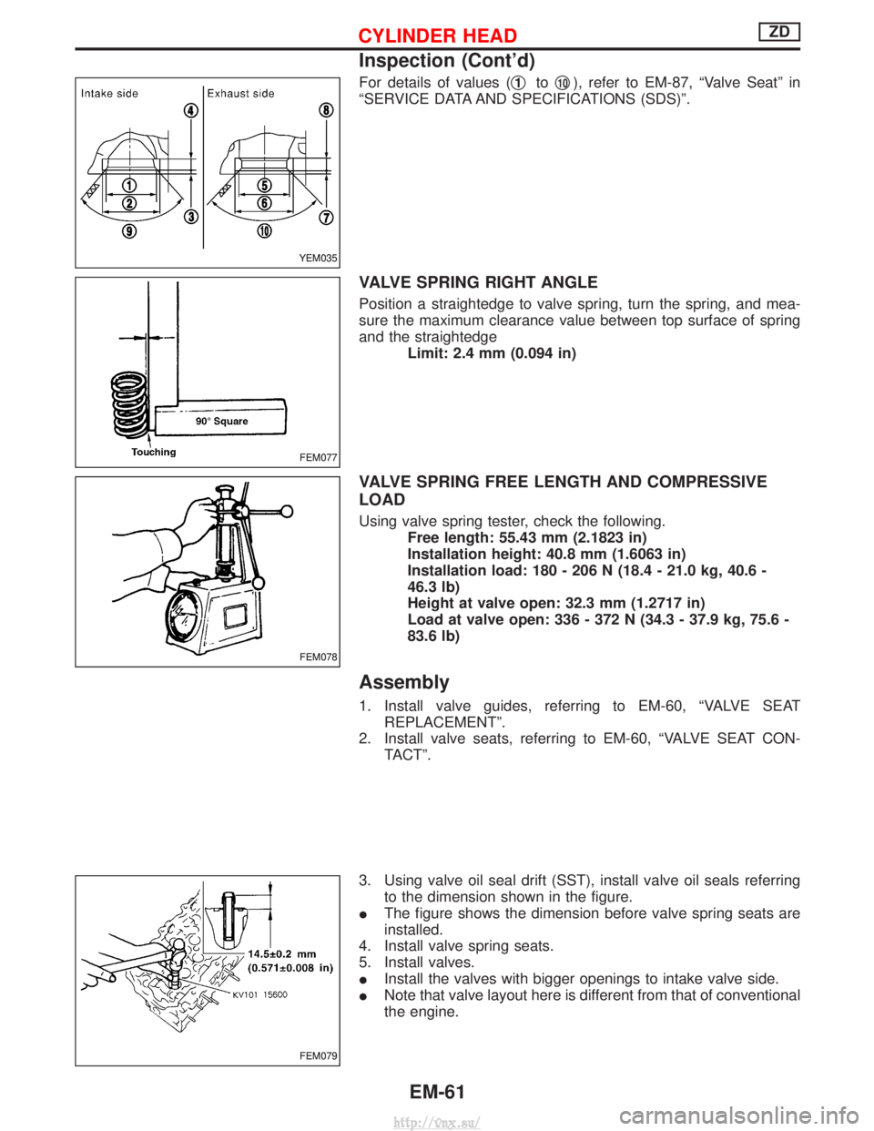
For details of values (q1toq10), refer to EM-87, ªValve Seatº in
ªSERVICE DATA AND SPECIFICATIONS (SDS)º.
VALVE SPRING RIGHT ANGLE
Position a straightedge to valve spring, turn the spring, and mea-
sure the maximum clearance value between top surface of spring
and the straightedge Limit: 2.4 mm (0.094 in)
VALVE SPRING FREE LENGTH AND COMPRESSIVE
LOAD
Using valve spring tester, check the following.Free length: 55.43 mm (2.1823 in)
Installation height: 40.8 mm (1.6063 in)
Installation load: 180 - 206 N (18.4 - 21.0 kg, 40.6 -
46.3 lb)
Height at valve open: 32.3 mm (1.2717 in)
Load at valve open: 336 - 372 N (34.3 - 37.9 kg, 75.6 -
83.6 lb)
Assembly
1. Install valve guides, referring to EM-60, ªVALVE SEATREPLACEMENTº.
2. Install valve seats, referring to EM-60, ªVALVE SEAT CON- TACTº.
3. Using valve oil seal drift (SST), install valve oil seals referring to the dimension shown in the figure.
I The figure shows the dimension before valve spring seats are
installed.
4. Install valve spring seats.
5. Install valves.
I Install the valves with bigger openings to intake valve side.
I Note that valve layout here is different from that of conventional
the engine.
YEM035
FEM077
FEM078
FEM079
CYLINDER HEADZD
Inspection (Cont'd)
EM-61
http://vnx.su/
Page 170 of 1833
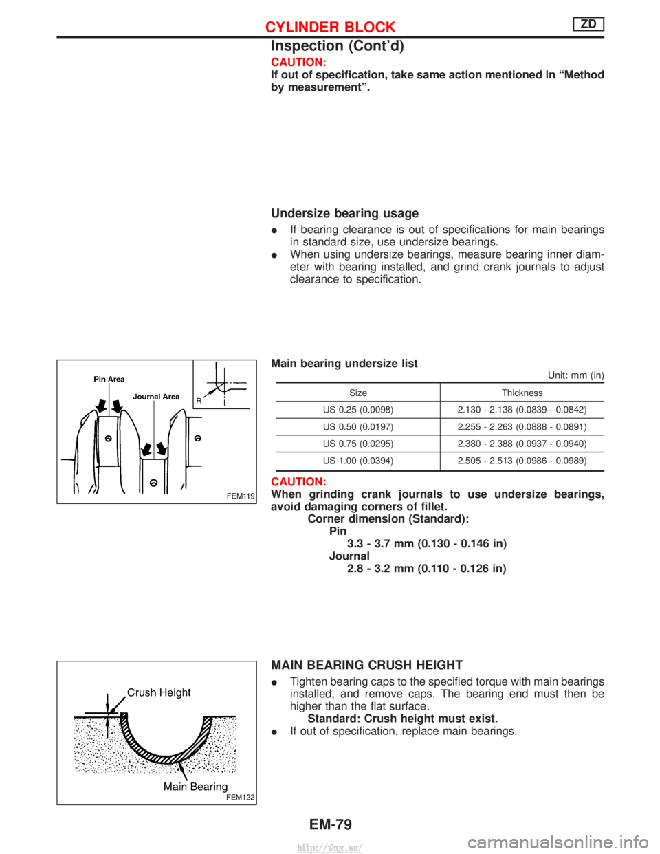
CAUTION:
If out of specification, take same action mentioned in ªMethod
by measurementº.
Undersize bearing usage
IIf bearing clearance is out of specifications for main bearings
in standard size, use undersize bearings.
I When using undersize bearings, measure bearing inner diam-
eter with bearing installed, and grind crank journals to adjust
clearance to specification.
Main bearing undersize list
Unit: mm (in)
Size Thickness
US 0.25 (0.0098) 2.130 - 2.138 (0.0839 - 0.0842)
US 0.50 (0.0197) 2.255 - 2.263 (0.0888 - 0.0891)
US 0.75 (0.0295) 2.380 - 2.388 (0.0937 - 0.0940)
US 1.00 (0.0394) 2.505 - 2.513 (0.0986 - 0.0989)
CAUTION:
When grinding crank journals to use undersize bearings,
avoid damaging corners of fillet.
Corner dimension (Standard):Pin3.3 - 3.7 mm (0.130 - 0.146 in)
Journal 2.8 - 3.2 mm (0.110 - 0.126 in)
MAIN BEARING CRUSH HEIGHT
I Tighten bearing caps to the specified torque with main bearings
installed, and remove caps. The bearing end must then be
higher than the flat surface.
Standard: Crush height must exist.
I If out of specification, replace main bearings.
FEM119
FEM122
CYLINDER BLOCKZD
Inspection (Cont'd)
EM-79
http://vnx.su/
Page 177 of 1833
VALVE SPRING
Free heightmm (in)55.43 (2.1823)
Pressure N (kg, lb) at height mm (in) 354 (36.1, 79.6) at 32.3 (1.2717)
Out-of-square mm (in) 2.4 (0.094)
VALVE LIFTER
Unit: mm (in)
Valve lifter outer diameter 34.455 - 34.465 (1.3565 - 1.3569)
Lifter guide inner diameter 34.495 - 34.515 (1.3581 - 1.3589)
Clearance between lifter and lifter guide 0.030 - 0.060 (0.0012 - 0.0024)
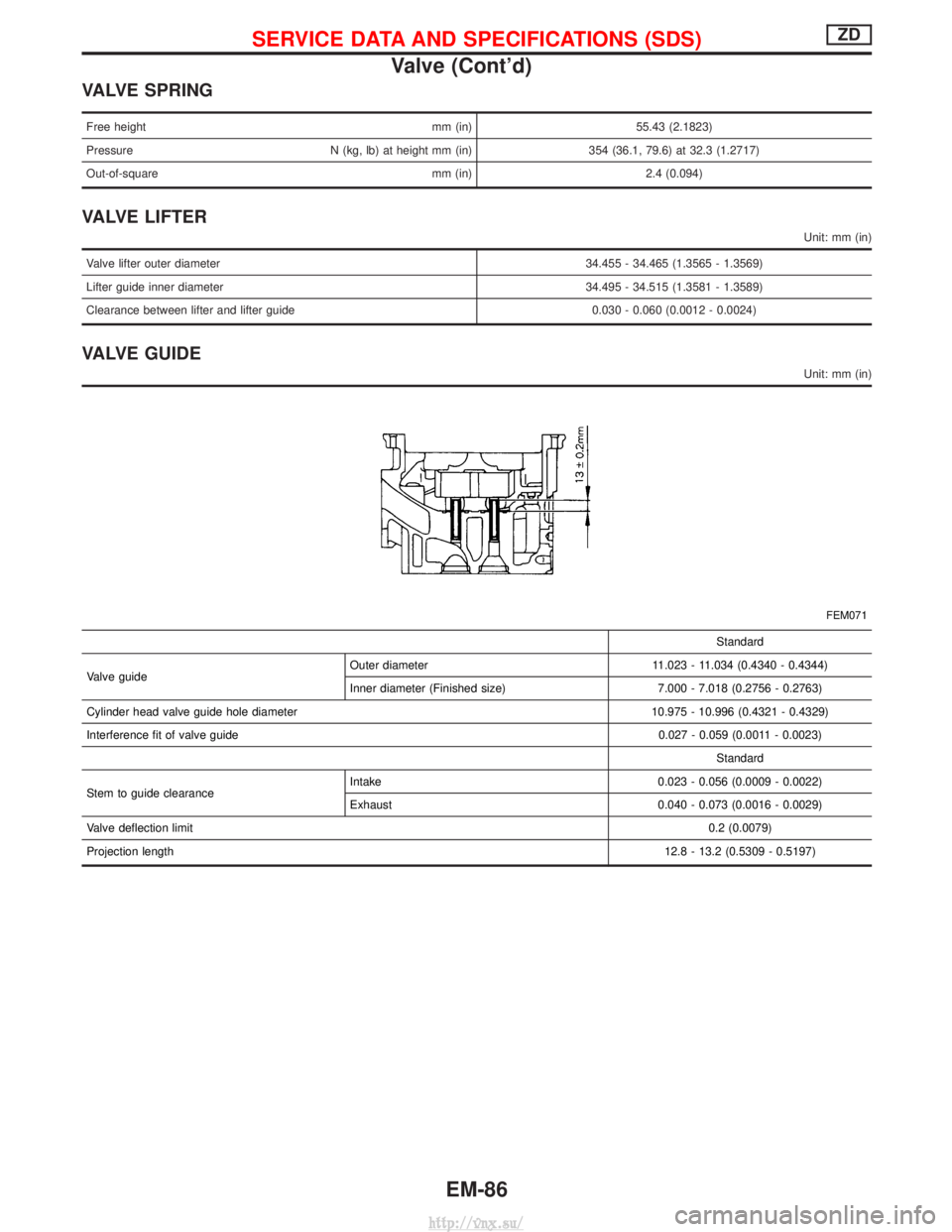
VALVE GUIDE
Unit: mm (in)
FEM071
Standard
Valve guide Outer diameter 11.023 - 11.034 (0.4340 - 0.4344)
Inner diameter (Finished size) 7.000 - 7.018 (0.2756 - 0.2763)
Cylinder head valve guide hole diameter 10.975 - 10.996 (0.4321 - 0.4329)
Interference fit of valve guide 0.027 - 0.059 (0.0011 - 0.0023)
Standard
Stem to guide clearance Intake 0.023 - 0.056 (0.0009 - 0.0022)
Exhaust 0.040 - 0.073 (0.0016 - 0.0029)
Valve deflection limit 0.2 (0.0079)
Projection length 12.8 - 13.2 (0.5309 - 0.5197)
SERVICE DATA AND SPECIFICATIONS (SDS)ZD
Valve (Cont'd)
EM-86
http://vnx.su/