height NISSAN TERRANO 2004 Service Owner's Manual
[x] Cancel search | Manufacturer: NISSAN, Model Year: 2004, Model line: TERRANO, Model: NISSAN TERRANO 2004Pages: 1833, PDF Size: 53.42 MB
Page 768 of 1833
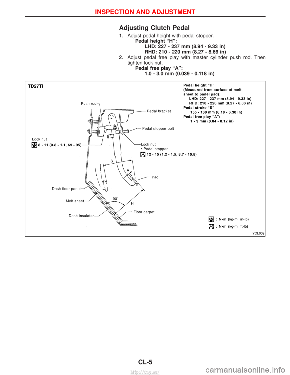
Adjusting Clutch Pedal
1. Adjust pedal height with pedal stopper.Pedal height ªHº:LHD: 227 - 237 mm (8.94 - 9.33 in)
RHD: 210 - 220 mm (8.27 - 8.66 in)
2. Adjust pedal free play with master cylinder push rod. Then tighten lock nut.Pedal free play ªAº: 1.0 - 3.0 mm (0.039 - 0.118 in)
YCL009
INSPECTION AND ADJUSTMENT
CL-5
http://vnx.su/
Page 775 of 1833
Clutch Cover and Flywheel
INSPECTION AND ADJUSTMENT
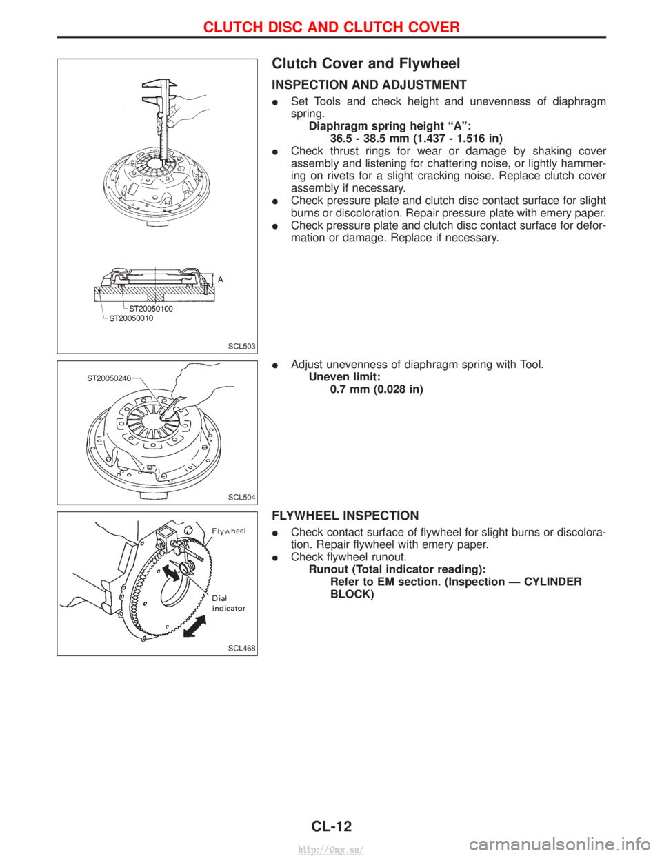
ISet Tools and check height and unevenness of diaphragm
spring.
Diaphragm spring height ªAº: 36.5 - 38.5 mm (1.437 - 1.516 in)
I Check thrust rings for wear or damage by shaking cover
assembly and listening for chattering noise, or lightly hammer-
ing on rivets for a slight cracking noise. Replace clutch cover
assembly if necessary.
I Check pressure plate and clutch disc contact surface for slight
burns or discoloration. Repair pressure plate with emery paper.
I Check pressure plate and clutch disc contact surface for defor-
mation or damage. Replace if necessary.
I Adjust unevenness of diaphragm spring with Tool.
Uneven limit: 0.7 mm (0.028 in)
FLYWHEEL INSPECTION
ICheck contact surface of flywheel for slight burns or discolora-
tion. Repair flywheel with emery paper.
I Check flywheel runout.
Runout (Total indicator reading): Refer to EM section. (Inspection Ð CYLINDER
BLOCK)
SCL503
SCL504
SCL468
CLUTCH DISC AND CLUTCH COVER
CL-12
http://vnx.su/
Page 777 of 1833
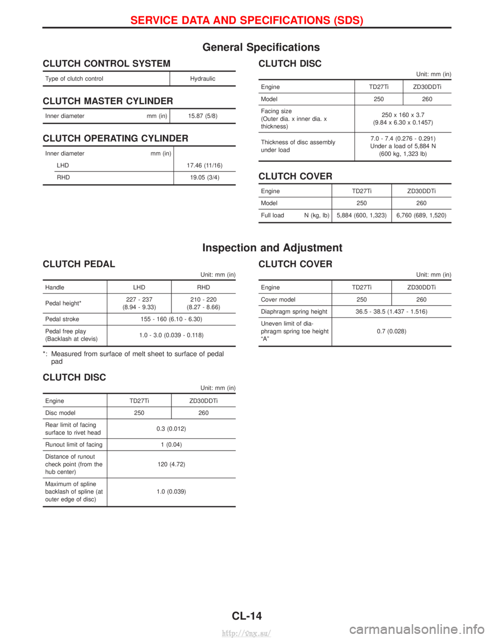
General Specifications
CLUTCH CONTROL SYSTEM
Type of clutch controlHydraulic
CLUTCH MASTER CYLINDER
Inner diametermm (in) 15.87 (5/8)
CLUTCH OPERATING CYLINDER
Inner diameter mm (in)
LHD 17.46 (11/16)
RHD 19.05 (3/4)
CLUTCH DISC
Unit: mm (in)
EngineTD27Ti ZD30DDTi
Model 250 260
Facing size
(Outer dia. x inner dia. x
thickness) 250 x 160 x 3.7
(9.84 x 6.30 x 0.1457)
Thickness of disc assembly
under load 7.0 - 7.4 (0.276 - 0.291)
Under a load of 5,884 N (600 kg, 1,323 lb)
CLUTCH COVER
Engine TD27TiZD30DDTi
Model 250 260
Full load N (kg, lb) 5,884 (600, 1,323) 6,760 (689, 1,520)
Inspection and Adjustment
CLUTCH PEDAL
Unit: mm (in)
Handle LHDRHD
Pedal height* 227 - 237
(8.94 - 9.33) 210 - 220
(8.27 - 8.66)
Pedal stroke 155 - 160 (6.10 - 6.30)
Pedal free play
(Backlash at clevis) 1.0 - 3.0 (0.039 - 0.118)
*: Measured from surface of melt sheet to surface of pedal
pad
CLUTCH DISC
Unit: mm (in)
Engine TD27TiZD30DDTi
Disc model 250 260
Rear limit of facing
surface to rivet head 0.3 (0.012)
Runout limit of facing 1 (0.04)
Distance of runout
check point (from the
hub center) 120 (4.72)
Maximum of spline
backlash of spline (at
outer edge of disc) 1.0 (0.039)
CLUTCH COVER
Unit: mm (in)
Engine
TD27TiZD30DDTi
Cover model 250 260
Diaphragm spring height 36.5 - 38.5 (1.437 - 1.516)
Uneven limit of dia-
phragm spring toe height
ªAº 0.7 (0.028)
SERVICE DATA AND SPECIFICATIONS (SDS)
CL-14
http://vnx.su/
Page 1052 of 1833
PROPELLER SHAFT &
DIFFERENTIAL CARRIER
SECTION
PD
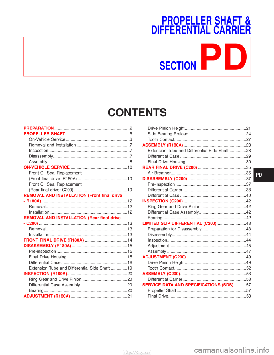
CONTENTS
PREPARATION ................................................................2
PROPELLER SHAFT ......................................................5
On-Vehicle Service ......................................................6
Removal and Installation .............................................7
Inspection.....................................................................7
Disassembly.................................................................7
Assembly .....................................................................8
ON-VEHICLE SERVICE ................................................10
Front Oil Seal Replacement
(Front final drive: R180A) ..........................................10
Front Oil Seal Replacement
(Rear final drive: C200) .............................................10
REMOVAL AND INSTALLATION (Front final drive
- R180A) ........................................................................\
.12
Removal .....................................................................12
Installation ..................................................................12
REMOVAL AND INSTALLATION (Rear final drive
- C200) ........................................................................\
...13
Removal .....................................................................13
Installation ..................................................................13
FRONT FINAL DRIVE (R180A) ....................................14
DISASSEMBLY (R180A) ...............................................15
Pre-inspection ............................................................15
Final Drive Housing ...................................................15
Differential Case ........................................................18
Extension Tube and Differential Side Shaft ..............19
INSPECTION (R180A) ...................................................20
Ring Gear and Drive Pinion ......................................20
Differential Case Assembly........................................20
Bearing.......................................................................20
ADJUSTMENT (R180A) ................................................21 Drive Pinion Height ....................................................21
Side Bearing Preload.................................................24
Tooth Contact.............................................................27
ASSEMBLY (R180A) .....................................................28
Extension Tube and Differential Side Shaft ..............28
Differential Case ........................................................29
Final Drive Housing ...................................................30
REAR FINAL DRIVE (C200) .........................................35
Air Breather................................................................36
DISASSEMBLY (C200) ..................................................37
Pre-inspection ............................................................37
Differential Carrier......................................................38
Differential Case ........................................................40
INSPECTION (C200) .....................................................42
Ring Gear and Drive Pinion ......................................42
Differential Case Assembly........................................42
Bearing.......................................................................42
LIMITED SLIP DIFFERENTIAL (C200) .........................43
Preparation for Disassembly .....................................43
Disassembly...............................................................44
Inspection...................................................................44
Adjustment .................................................................45
Assembly ...................................................................47
ADJUSTMENT (C200) ...................................................49
Drive Pinion Height ....................................................49
Tooth Contact.............................................................52
ASSEMBLY (C200) ........................................................53
Differential Carrier......................................................53
SERVICE DATA AND SPECIFICATIONS (SDS) ..........57
Propeller Shaft ...........................................................57
Final Drive..................................................................58
http://vnx.su/
Page 1053 of 1833
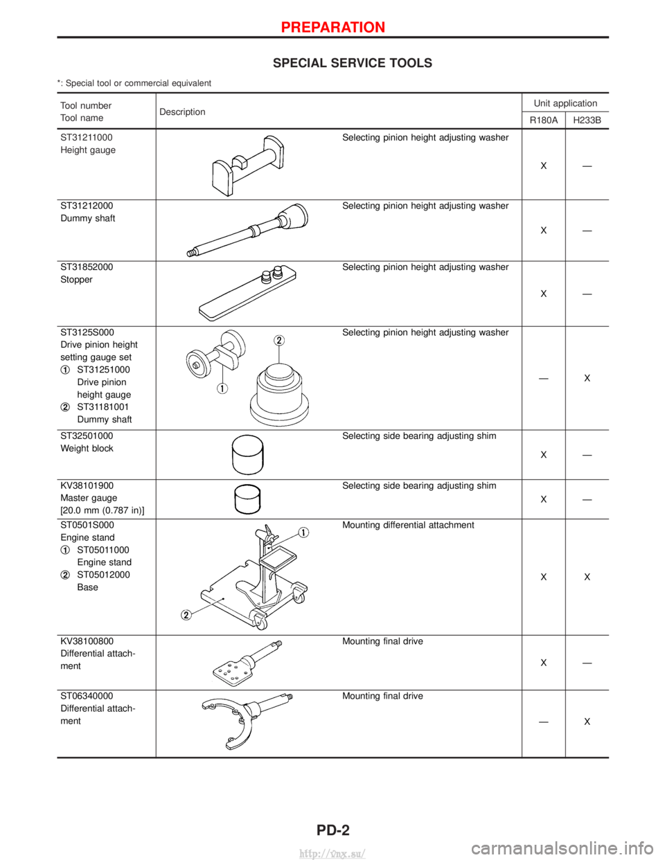
SPECIAL SERVICE TOOLS
*: Special tool or commercial equivalent
Tool number
Tool nameDescription Unit application
R180A H233B
ST31211000
Height gauge
Selecting pinion height adjusting washer
XÐ
ST31212000
Dummy shaft
Selecting pinion height adjusting washer XÐ
ST31852000
Stopper
Selecting pinion height adjusting washer XÐ
ST3125S000
Drive pinion height
setting gauge set
q
1ST31251000
Drive pinion
height gauge
q
2ST31181001
Dummy shaft
Selecting pinion height adjusting washer
ÐX
ST32501000
Weight block
Selecting side bearing adjusting shim XÐ
KV38101900
Master gauge
[20.0 mm (0.787 in)]
Selecting side bearing adjusting shim XÐ
ST0501S000
Engine stand
q
1ST05011000
Engine stand
q
2ST05012000
Base
Mounting differential attachment
XX
KV38100800
Differential attach-
ment
Mounting final drive XÐ
ST06340000
Differential attach-
ment
Mounting final drive ÐX
PREPARATION
PD-2
http://vnx.su/
Page 1072 of 1833
To avoid confusion while calculating bearing shims, it is absolutely
necessary to stay with the metric system. If you measure anything
in inches, the results MUST be converted to the metric system.
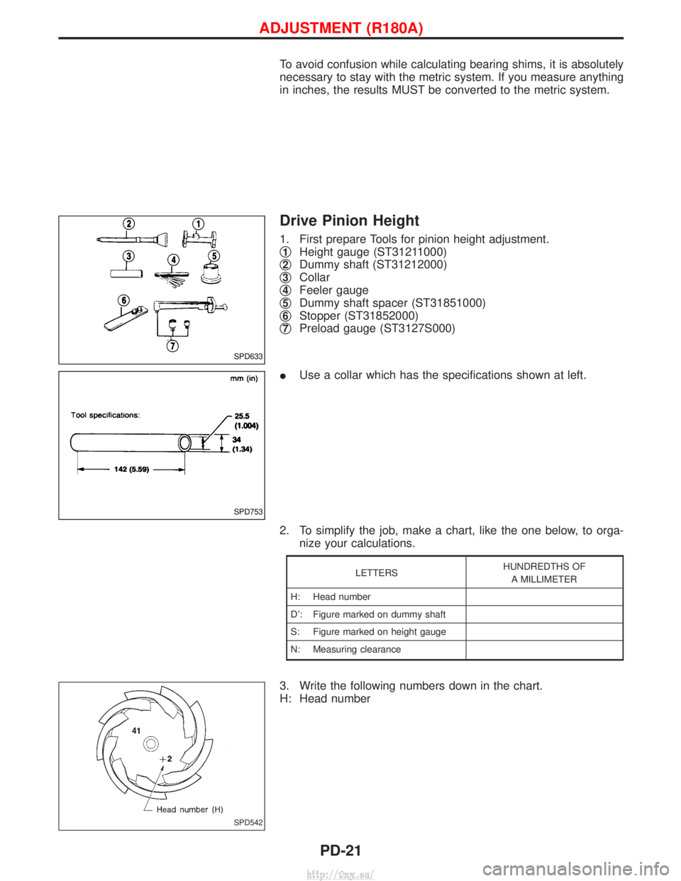
Drive Pinion Height
1. First prepare Tools for pinion height adjustment.
q
1Height gauge (ST31211000)
q
2Dummy shaft (ST31212000)
q
3Collar
q
4Feeler gauge
q
5Dummy shaft spacer (ST31851000)
q
6Stopper (ST31852000)
q
7Preload gauge (ST3127S000)
I Use a collar which has the specifications shown at left.
2. To simplify the job, make a chart, like the one below, to orga- nize your calculations.
LETTERS HUNDREDTHS OF
A MILLIMETER
H: Head number
D¢ : Figure marked on dummy shaft
S: Figure marked on height gauge
N: Measuring clearance
3. Write the following numbers down in the chart.
H: Head number
SPD633
SPD753
SPD542
ADJUSTMENT (R180A)
PD-21
http://vnx.su/
Page 1073 of 1833
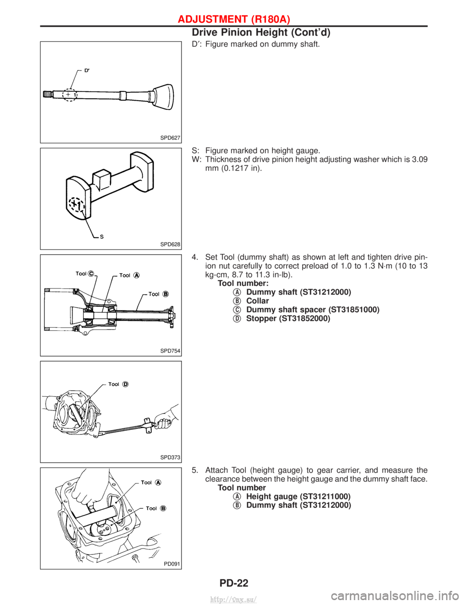
D¢: Figure marked on dummy shaft.
S: Figure marked on height gauge.
W: Thickness of drive pinion height adjusting washer which is 3.09 mm (0.1217 in).
4. Set Tool (dummy shaft) as shown at left and tighten drive pin- ion nut carefully to correct preload of 1.0 to 1.3 N ×m (10 to 13
kg-cm, 8.7 to 11.3 in-lb). Tool number: q
ADummy shaft (ST31212000)
q
BCollar
q
CDummy shaft spacer (ST31851000)
q
DStopper (ST31852000)
5. Attach Tool (height gauge) to gear carrier, and measure the clearance between the height gauge and the dummy shaft face.Tool number q
AHeight gauge (ST31211000)
q
BDummy shaft (ST31212000)
SPD627
SPD628
SPD754
SPD373
PD091
ADJUSTMENT (R180A)
Drive Pinion Height (Cont'd)
PD-22
http://vnx.su/
Page 1074 of 1833
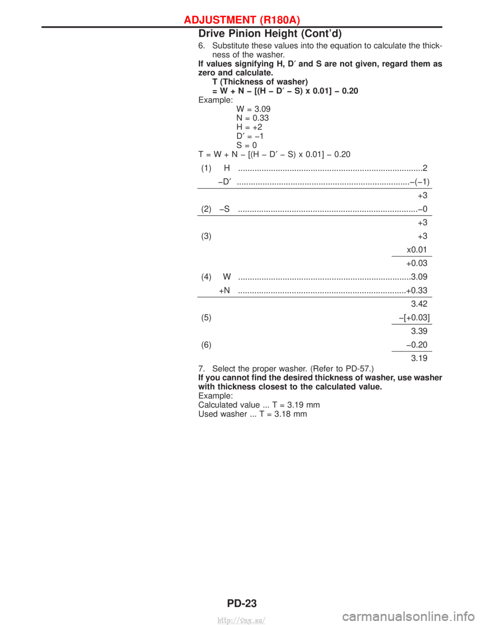
6. Substitute these values into the equation to calculate the thick-ness of the washer.
If values signifying H, D¢ and S are not given, regard them as
zero and calculate. T (Thickness of washer)
=W+Nþ[(HþD ¢þ S) x 0.01] þ 0.20
Example: W = 3.09
N = 0.33
H=+2
D¢=þ1
S=0
T=W+Nþ[(HþD ¢þ S) x 0.01] þ 0.20
(1) H ........................................................................\
.......2
þD¢ ........................................................................\
..þ(þ1)
+3
(2) þS ........................................................................\
.....þ0 +3
(3) +3 x0.01
+0.03
(4) W ........................................................................\
..3.09 +N ........................................................................\
+0.33 3.42
(5) þ[+0.03] 3.39
(6) þ0.20 3.19
7. Select the proper washer. (Refer to PD-57.)
If you cannot find the desired thickness of washer, use washer
with thickness closest to the calculated value.
Example:
Calculated value ... T = 3.19 mm
Used washer ... T = 3.18 mm
ADJUSTMENT (R180A)
Drive Pinion Height (Cont'd)
PD-23
http://vnx.su/
Page 1081 of 1833
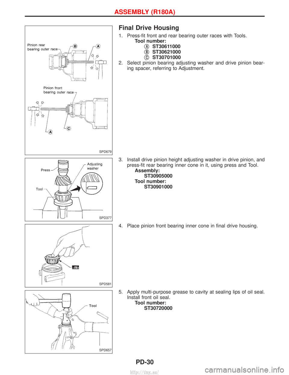
Final Drive Housing
1. Press-fit front and rear bearing outer races with Tools.Tool number:q
AST30611000
q
BST30621000
q
CST30701000
2. Select pinion bearing adjusting washer and drive pinion bear- ing spacer, referring to Adjustment.
3. Install drive pinion height adjusting washer in drive pinion, and press-fit rear bearing inner cone in it, using press and Tool.Assembly: ST30905000
Tool number: ST30901000
4. Place pinion front bearing inner cone in final drive housing.
5. Apply multi-purpose grease to cavity at sealing lips of oil seal. Install front oil seal.Tool number: ST30720000
SPD679
SPD377
SPD581
SPD657
ASSEMBLY (R180A)
PD-30
http://vnx.su/
Page 1100 of 1833
To avoid confusion while calculating bearing shims, it is absolutely
necessary to stay with the metric system. If you measure anything
in inches, the results MUST be converted to the metric system.
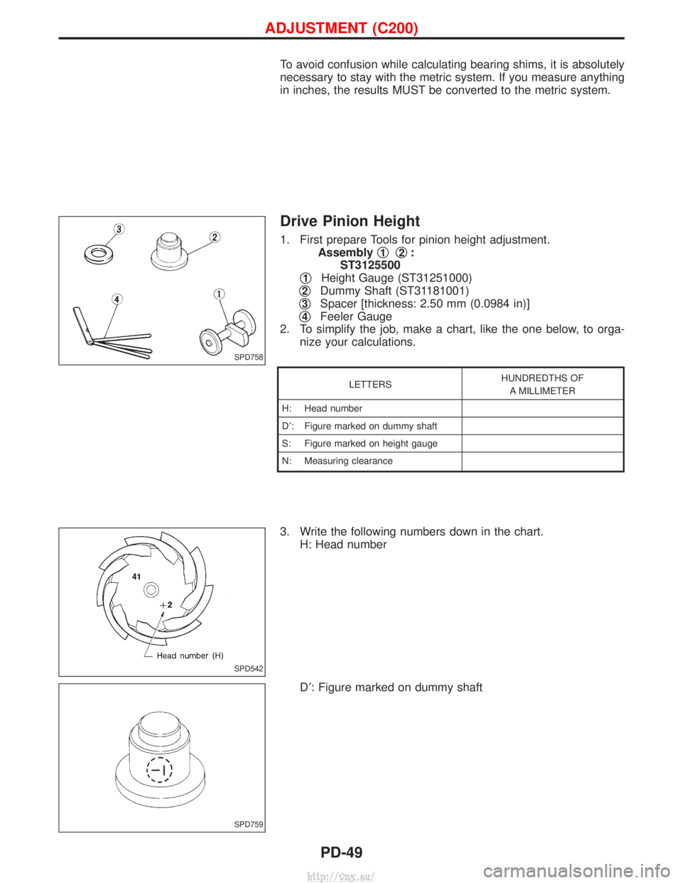
Drive Pinion Height
1. First prepare Tools for pinion height adjustment.Assembly q
1q2:
ST3125500
q
1Height Gauge (ST31251000)
q
2Dummy Shaft (ST31181001)
q
3Spacer [thickness: 2.50 mm (0.0984 in)]
q
4Feeler Gauge
2. To simplify the job, make a chart, like the one below, to orga- nize your calculations.
LETTERS HUNDREDTHS OF
A MILLIMETER
H: Head number
D¢ : Figure marked on dummy shaft
S: Figure marked on height gauge
N: Measuring clearance
3. Write the following numbers down in the chart. H: Head number
D¢: Figure marked on dummy shaft
SPD758
SPD542
SPD759
ADJUSTMENT (C200)
PD-49
http://vnx.su/