bulb NISSAN TERRANO 2004 Service Repair Manual
[x] Cancel search | Manufacturer: NISSAN, Model Year: 2004, Model line: TERRANO, Model: NISSAN TERRANO 2004Pages: 1833, PDF Size: 53.42 MB
Page 309 of 1833
IIf the battery is disconnected, the emission-related diagnostic information will be lost after approx.
24 hours.
I Erasing the emission-related diagnostic information using CONSULT-II is easier and quicker than
switching the diagnostic test mode using the data link connector.
NATS (Nissan Anti-Theft System)
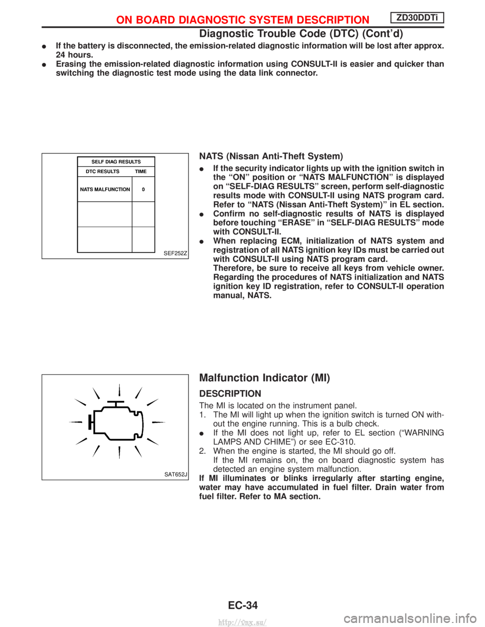
IIf the security indicator lights up with the ignition switch in
the ªONº position or ªNATS MALFUNCTIONº is displayed
on ªSELF-DIAG RESULTSº screen, perform self-diagnostic
results mode with CONSULT-II using NATS program card.
Refer to ªNATS (Nissan Anti-Theft System)º in EL section.
I Confirm no self-diagnostic results of NATS is displayed
before touching ªERASEº in ªSELF-DIAG RESULTSº mode
with CONSULT-II.
I When replacing ECM, initialization of NATS system and
registration of all NATS ignition key IDs must be carried out
with CONSULT-II using NATS program card.
Therefore, be sure to receive all keys from vehicle owner.
Regarding the procedures of NATS initialization and NATS
ignition key ID registration, refer to CONSULT-II operation
manual, NATS.
Malfunction Indicator (MI)
DESCRIPTION
The MI is located on the instrument panel.
1. The MI will light up when the ignition switch is turned ON with-
out the engine running. This is a bulb check.
I If the MI does not light up, refer to EL section (ªWARNING
LAMPS AND CHIMEº) or see EC-310.
2. When the engine is started, the MI should go off. If the MI remains on, the on board diagnostic system has
detected an engine system malfunction.
If MI illuminates or blinks irregularly after starting engine,
water may have accumulated in fuel filter. Drain water from
fuel filter. Refer to MA section.
SEF252Z
SAT652J
ON BOARD DIAGNOSTIC SYSTEM DESCRIPTIONZD30DDTi
Diagnostic Trouble Code (DTC) (Cont'd)
EC-34
http://vnx.su/
Page 310 of 1833
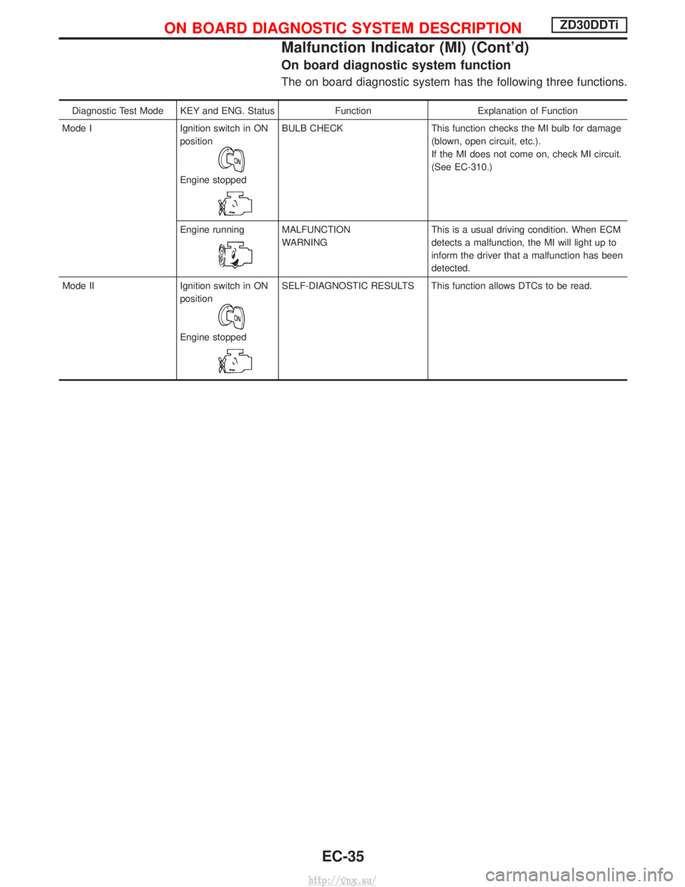
On board diagnostic system function
The on board diagnostic system has the following three functions.
Diagnostic Test Mode KEY and ENG. StatusFunctionExplanation of Function
Mode I Ignition switch in ON
position
Engine stopped
BULB CHECK This function checks the MI bulb for damage
(blown, open circuit, etc.).
If the MI does not come on, check MI circuit.
(See EC-310.)
Engine running
MALFUNCTION
WARNING This is a usual driving condition. When ECM
detects a malfunction, the MI will light up to
inform the driver that a malfunction has been
detected.
Mode II Ignition switch in ON position
Engine stopped
SELF-DIAGNOSTIC RESULTS This function allows DTCs to be read.
ON BOARD DIAGNOSTIC SYSTEM DESCRIPTIONZD30DDTi
Malfunction Indicator (MI) (Cont'd)
EC-35
http://vnx.su/
Page 312 of 1833
Diagnostic test mode I Ð Bulb check
In this mode, the MI on the instrument panel should stay ON. If it remains OFF, check the bulb. Refer to EL
section, ªWARNING LAMPS AND CHIMEº or see EC-310.
Diagnostic test mode I Ð Malfunction warning
MICondition
ON When the malfunction is detected or the ECM's CPU is malfunctioning.
OFF No malfunction.
Diagnostic test mode II Ð Self-diagnostic results
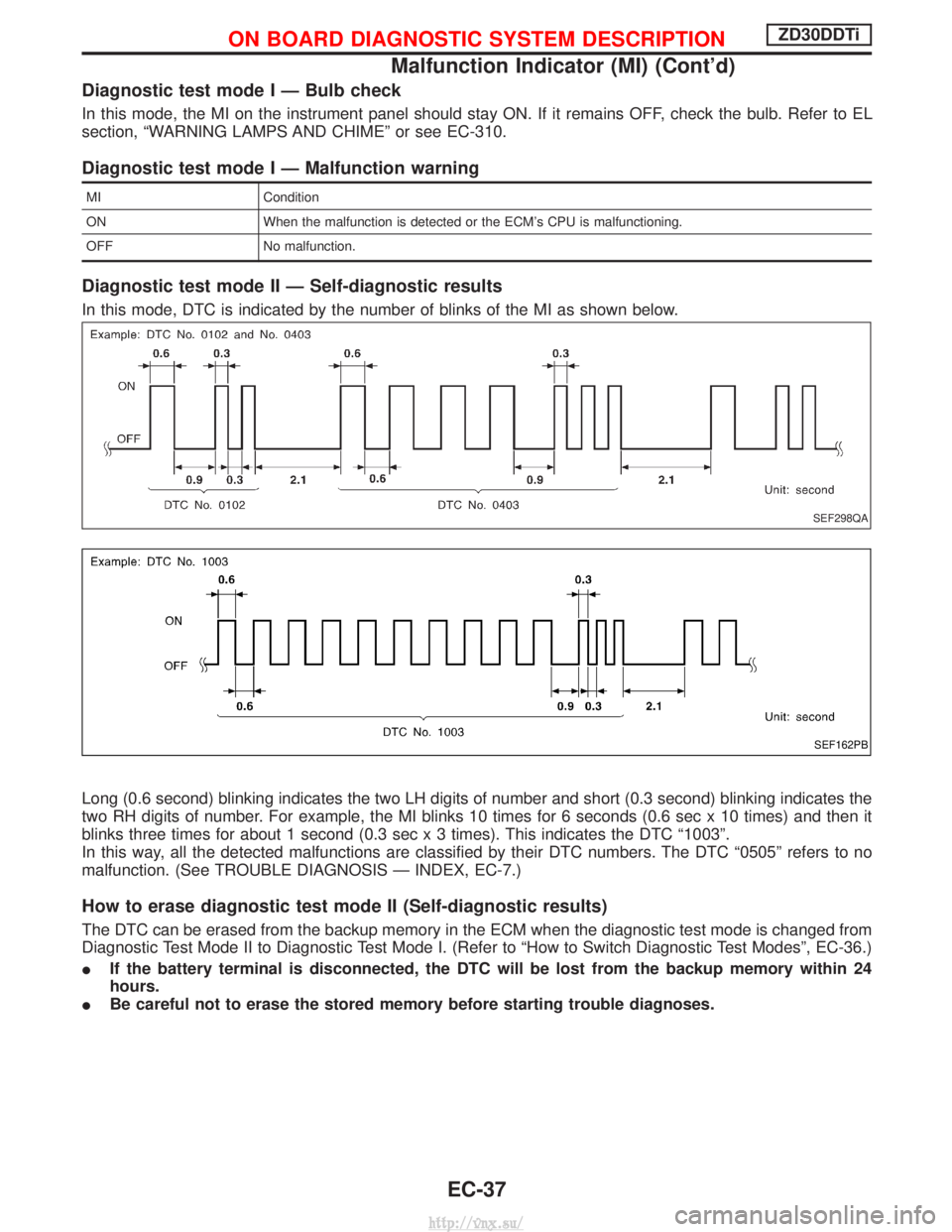
In this mode, DTC is indicated by the number of blinks of the MI as shown below.
Long (0.6 second) blinking indicates the two LH digits of number and short (0.3 second) blinking indicates the
two RH digits of number. For example, the MI blinks 10 times for 6 seconds (0.6 sec x 10 times) and then it
blinks three times for about 1 second (0.3 sec x 3 times). This indicates the DTC ª1003º.
In this way, all the detected malfunctions are classified by their DTC numbers. The DTC ª0505º refers to no
malfunction. (See TROUBLE DIAGNOSIS Ð INDEX, EC-7.)
How to erase diagnostic test mode II (Self-diagnostic results)
The DTC can be erased from the backup memory in the ECM when the diagnostic test mode is changed from
Diagnostic Test Mode II to Diagnostic Test Mode I. (Refer to ªHow to Switch Diagnostic Test Modesº, EC-36.)
I If the battery terminal is disconnected, the DTC will be lost from the backup memory within 24
hours.
I Be careful not to erase the stored memory before starting trouble diagnoses.
SEF298QA
SEF162PB
ON BOARD DIAGNOSTIC SYSTEM DESCRIPTIONZD30DDTi
Malfunction Indicator (MI) (Cont'd)
EC-37
http://vnx.su/
Page 620 of 1833
How to Erase DTC (Without CONSULT-II)
1. If the ignition switch stays ªONº after repair work, be sure to turn ignition switch ªOFFº once. Wait at least5 seconds and then turn it ªONº (engine stopped) again.
2. Change the diagnostic test mode from Mode II to Mode I by using the data link connector. (See EC-346.)
The emission related diagnostic information in the ECM can be erased by changing the diagnostic test mode.
I If the battery is disconnected, the emission-related diagnostic information will be lost after approx.
24 hours.
I Erasing the emission-related diagnostic information using CONSULT-II is easier and quicker than
switching the diagnostic test mode using the data link connector.
Malfunction Indicator (MI)
1. The malfunction indicator will light up when the ignition switch
is turned ON without the engine running. This is a bulb check.
I If the malfunction indicator does not light up, refer to EL sec-
tion (ªWARNING LAMPS/WIRING DIAGRAMº) or see MI &
DATA LINK CONNECTORS.
2. When the engine is started, the malfunction indicator should go off.
If the lamp remains on, the on board diagnostic system has
detected an engine system malfunction.
If MI illuminates or flashes irregularly after starting engine,
water may have accumulated in fuel filter. Drain water from
fuel filter.
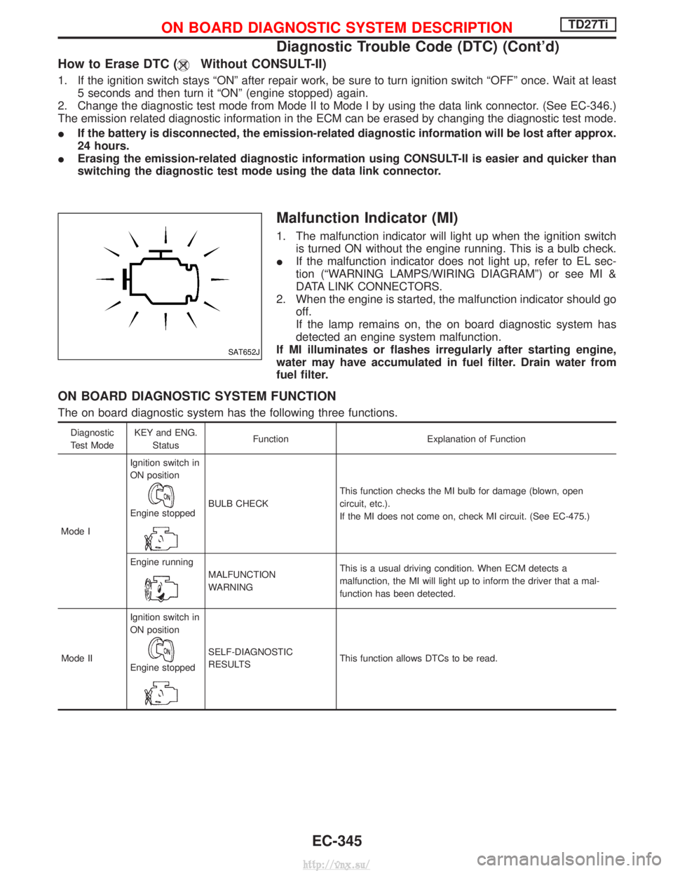
ON BOARD DIAGNOSTIC SYSTEM FUNCTION
The on board diagnostic system has the following three functions.
Diagnostic
Test Mode KEY and ENG.
Status Function Explanation of Function
Mode I Ignition switch in
ON position
Engine stoppedBULB CHECK
This function checks the MI bulb for damage (blown, open
circuit, etc.).
If the MI does not come on, check MI circuit. (See EC-475.)
Engine running
MALFUNCTION
WARNING This is a usual driving condition. When ECM detects a
malfunction, the MI will light up to inform the driver that a mal-
function has been detected.
Mode II Ignition switch in
ON position
Engine stopped
SELF-DIAGNOSTIC
RESULTS
This function allows DTCs to be read.
SAT652J
ON BOARD DIAGNOSTIC SYSTEM DESCRIPTIONTD27Ti
Diagnostic Trouble Code (DTC) (Cont'd)
EC-345
http://vnx.su/
Page 622 of 1833
DIAGNOSTIC TEST MODE IÐBULB CHECK
In this mode, the MALFUNCTION INDICATOR on the instrument panel should stay ON. If it remains OFF,
check the bulb. Refer to EL section (ªWARNING LAMPS/WIRING DIAGRAMº) or see EC-475.
DIAGNOSTIC TEST MODE IÐMALFUNCTION WARNING
MICondition
ON When a malfunction is detected or the ECM's CPU is malfunctioning.
OFF No malfunction.
I These Diagnostic Trouble Code Numbers are clarified in Diagnostic Test Mode II (SELF-DIAGNOSTIC
RESULTS).
DIAGNOSTIC TEST MODE IIÐSELF-DIAGNOSTIC RESULTS
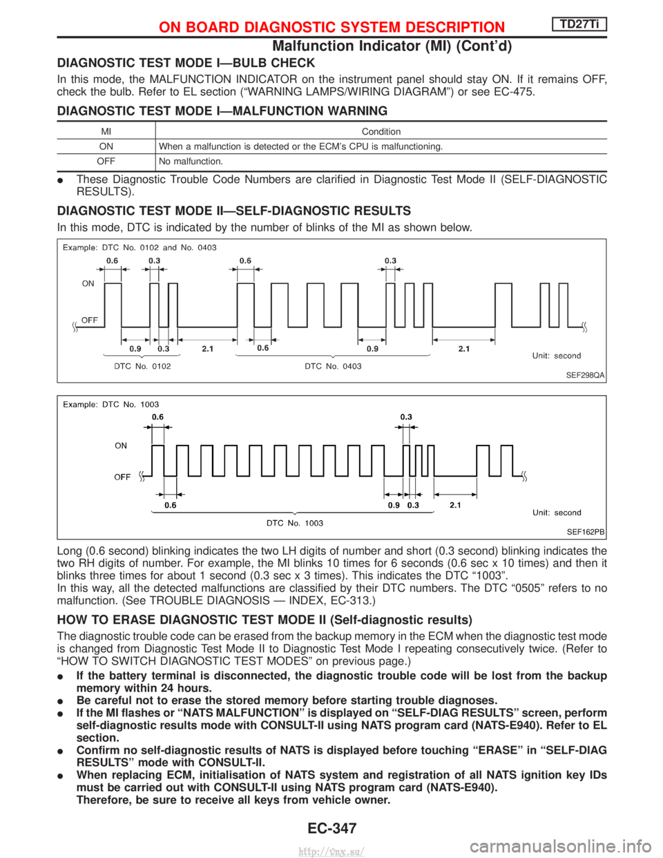
In this mode, DTC is indicated by the number of blinks of the MI as shown below.
Long (0.6 second) blinking indicates the two LH digits of number and short (0.3 second) blinking indicates the
two RH digits of number. For example, the MI blinks 10 times for 6 seconds (0.6 sec x 10 times) and then it
blinks three times for about 1 second (0.3 sec x 3 times). This indicates the DTC ª1003º.
In this way, all the detected malfunctions are classified by their DTC numbers. The DTC ª0505º refers to no
malfunction. (See TROUBLE DIAGNOSIS Ð INDEX, EC-313.)
HOW TO ERASE DIAGNOSTIC TEST MODE II (Self-diagnostic results)
The diagnostic trouble code can be erased from the backup memory in the ECM when the diagnostic test mode
is changed from Diagnostic Test Mode II to Diagnostic Test Mode I repeating consecutively twice. (Refer to
ªHOW TO SWITCH DIAGNOSTIC TEST MODESº on previous page.)
IIf the battery terminal is disconnected, the diagnostic trouble code will be lost from the backup
memory within 24 hours.
I Be careful not to erase the stored memory before starting trouble diagnoses.
I If the MI flashes or ªNATS MALFUNCTIONº is displayed on ªSELF-DIAG RESULTSº screen, perform
self-diagnostic results mode with CONSULT-II using NATS program card (NATS-E940). Refer to EL
section.
I Confirm no self-diagnostic results of NATS is displayed before touching ªERASEº in ªSELF-DIAG
RESULTSº mode with CONSULT-II.
I When replacing ECM, initialisation of NATS system and registration of all NATS ignition key IDs
must be carried out with CONSULT-II using NATS program card (NATS-E940).
Therefore, be sure to receive all keys from vehicle owner.
SEF298QA
SEF162PB
ON BOARD DIAGNOSTIC SYSTEM DESCRIPTIONTD27Ti
Malfunction Indicator (MI) (Cont'd)
EC-347
http://vnx.su/
Page 702 of 1833
Component Description
Malfunction Indicator (MI) is located on the instrument panel. When the ignition switch is turned ON without
engine running, MI will light up. This is a bulb check. When the engine is started, MI should go off. If MI remains
on, the on board diagnostic system has detected an engine system malfunction.
On Board Diagnosis Logic
DTC No.Trouble diagnosis name DTC detecting condition Possible cause
P0650
0907 Malfunction indicator (MI) control cir-
cuit I
An excessively high voltage is sent
to ECM through the MI circuit
under the condition that calls for MI
light up.
I An excessively low voltage is sent
to ECM through the MI circuit
under the condition that calls for MI
not to light up. I
Harness or connectors
(MI circuit is open or shorted.)
I MI
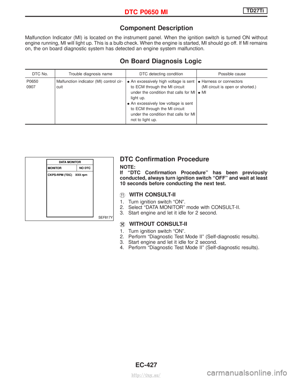
DTC Confirmation Procedure
NOTE:
If ªDTC Confirmation Procedureº has been previously
conducted, always turn ignition switch ªOFFº and wait at least
10 seconds before conducting the next test.
WITH CONSULT-II
1. Turn ignition switch ªONº.
2. Select ªDATA MONITORº mode with CONSULT-II.
3. Start engine and let it idle for 2 second.
WITHOUT CONSULT-II
1. Turn ignition switch ªONº.
2. Perform ªDiagnostic Test Mode IIº (Self-diagnostic results).
3. Start engine and let it idle for 2 second.
4. Perform ªDiagnostic Test Mode IIº (Self-diagnostic results).
SEF817Y
DTC P0650 MITD27Ti
EC-427
http://vnx.su/
Page 1233 of 1833
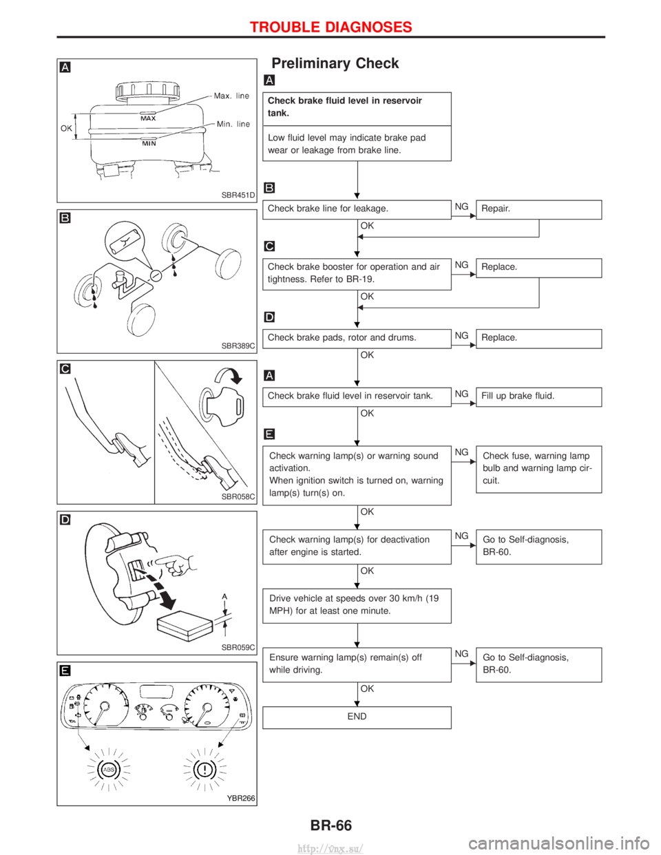
Preliminary Check
Check brake fluid level in reservoir
tank.
---------------------------------------------------------------------------------------------------------------------------------------------------------------------------------------------------------------------------------------------------------------------------------------------------------------- Low fluid level may indicate brake pad
wear or leakage from brake line.
Check brake line for leakage.
OKENG Repair.
F
Check brake booster for operation and air
tightness. Refer to BR-19.
OK
ENGReplace.
F
Check brake pads, rotor and drums.
OKENGReplace.
Check brake fluid level in reservoir tank.
OKENGFill up brake fluid.
Check warning lamp(s) or warning sound
activation.
When ignition switch is turned on, warning
lamp(s) turn(s) on.
OK
ENG
Check fuse, warning lamp
bulb and warning lamp cir-
cuit.
Check warning lamp(s) for deactivation
after engine is started.
OK
ENGGo to Self-diagnosis,
BR-60.
Drive vehicle at speeds over 30 km/h (19
MPH) for at least one minute.
Ensure warning lamp(s) remain(s) off
while driving.
OK
ENGGo to Self-diagnosis,
BR-60.
END
SBR451D
SBR389C
SBR058C
SBR059C
YBR266
H
H
H
H
H
H
H
H
H
TROUBLE DIAGNOSES
BR-66
http://vnx.su/
Page 1235 of 1833
Diagnostic Procedure 1 (Not self-diagnostic
item)
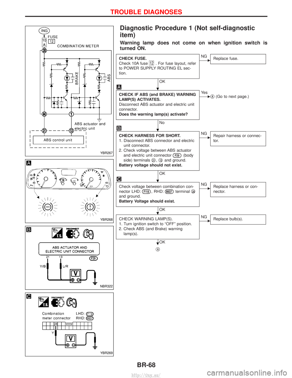
Warning lamp does not come on when ignition switch is
turned ON.
CHECK FUSE.
Check 10A fuse
12. For fuse layout, refer
to POWER SUPPLY ROUTING EL sec-
tion.
OK
ENG Replace fuse.
CHECK IF ABS (and BRAKE) WARNING
LAMP(S) ACTIVATES.
Disconnect ABS actuator and electric unit
connector.
Does the warning lamp(s) activate?
No
EYe s
qA(Go to next page.)
CHECK HARNESS FOR SHORT.
1. Disconnect ABS connector and electric
unit connector.
2. Check voltage between ABS actuator and electric unit connector
F29(body
side) terminals q
21,q13and ground.
Battery voltage should not exist.
OK
ENG Repair harness or connec-
tor.
Check voltage between combination con-
nector LHD:
F118, RHD:M837terminal q28
and ground.
Battery Voltage should exist.
OK
ENG
Replace harness or con-
nector.
CHECK WARNING LAMP(S).
1. Turn ignition switch to ªOFFº position.
2. Check ABS (and Brake) warning lamp(s).
OK
ENG Replace bulb(s).
qA
YBR267
YBR268
NBR322
YBR269
H
H
H
H
H
TROUBLE DIAGNOSES
BR-68
http://vnx.su/
Page 1494 of 1833
ELECTRICAL SYSTEMSECTION
EL
When you read wiring diagrams:
I Read GI section, ªHOW TO READ WIRING DIAGRAMSº.
CONTENTS
PRECAUTIONS ...............................................................4
Supplemental Restraint System (SRS) ²AIR
BAG² and²SEAT BELT PRE-TENSIONER² ...............4
Wiring Diagrams and Trouble Diagnoses....................4
HARNESS CONNECTOR ................................................5
Description ...................................................................5
STANDARDIZED RELAYS ..............................................6
Description ...................................................................6
POWER SUPPLY ROUTING ...........................................8
Schematic ....................................................................8
Wiring Diagram - POWER - ......................................10
Fuse ........................................................................\
...19
Fusible Link................................................................19
Circuit Breaker Inspection .........................................19
GROUND DISTRIBUTION .............................................20
COMBINATION SWITCH ...............................................25
Check ........................................................................\
.25
Replacement ..............................................................26
STEERING SWITCH ......................................................27
Check ........................................................................\
.27
HEADLAMP - Without Daytime Light System - .........28
Wiring Diagram - H/LAMP -.......................................28
Trouble Diagnoses.....................................................31
HEADLAMP - Daytime Light System - .......................32
Operation ...................................................................32
System Description ....................................................32
Schematic ..................................................................33
Wiring Diagram - DTRL - ...........................................34
Trouble Diagnoses.....................................................40
HEADLAMP - Headlamp Aiming Control - .................41
Description .................................................................41
Replacing Headlamp Aiming Actuator .......................42
Wiring Diagram - H/AIM - ..........................................43
Trouble Diagnoses.....................................................46 HEADLAMP
...................................................................47
Bulb Replacement .....................................................47
Aiming Adjustment .....................................................47
EXTERIOR LAMP ..........................................................49
Wiring Diagram - TAIL/L - ..........................................49
Wiring Diagram - STOP/L - .......................................52
Wiring Diagram - BACK/L - .......................................53
Wiring Diagram - F/FOG - .........................................55
Front Fog Lamp Aiming Adjustment ..........................57
Wiring Diagram - R/FOG -.........................................58
System Description ....................................................59
Schematic ..................................................................61
Wiring Diagram - TURN - ..........................................62
Trouble Diagnoses.....................................................66
INTERIOR LAMP ...........................................................67
Schematic ..................................................................67
Wiring Diagram - ILL - ...............................................68
System Description ....................................................72
Wiring Diagram - INT/L - ...........................................74
Trouble Diagnoses.....................................................78
METER AND GAUGES .................................................82
System Description ....................................................82
Combination Meter ....................................................84
Schematic ..................................................................85
Wiring Diagram - METER - .......................................86
Combination Meter Self-Diagnosis ............................90
Trouble Diagnoses.....................................................92
Components Inspection .............................................97
Fuel Level Sensor Unit Check...................................98
Thermal Transmitter Check .......................................98
WARNING LAMPS AND CHIME ...................................99
Schematic ..................................................................99
Wiring Diagram - WARN - .......................................100
Electrical Components Inspection ........................... 110
http://vnx.su/
Page 1495 of 1833
Oil Pressure Switch Check ...................................... 110
Wiring Diagram - CHIME - ...................................... 111
WIPER AND WASHER ................................................ 112
Wiring Diagram - WIPER - ...................................... 112
Wiring Diagram - WIP/R -........................................ 114
Installation ................................................................ 116
Washer Nozzle Adjustment ..................................... 117
Check Valve ............................................................. 117
Wiring Diagram - HLC - ........................................... 118
HORN, CIGARETTE LIGHTER AND CLOCK ............122
Wiring Diagram - HORN - .......................................122
Wiring Diagram - CIGAR -.......................................123
Wiring Diagram - CLOCK -......................................124
REAR WINDOW DEFOGGER AND DOOR
MIRROR DEFOGGER .................................................125
System Description ..................................................125
Wiring Diagram - DEF - ...........................................126
Trouble Diagnoses...................................................128
Filament Check ........................................................132
Filament Repair .......................................................133
AUDIO ........................................................................\
..134
System Description ..................................................134
Schematic ................................................................136
Wiring Diagram - AUDIO - .......................................138
Wiring Diagram - REMOTE -...................................145
Trouble Diagnoses...................................................147
Inspection.................................................................149
Location of Roof Mounted Antenna .........................150
HEATED SEAT ............................................................151
Wiring Diagram - HSEAT - ......................................151
SUNROOF ....................................................................153
Wiring Diagram - SROOF - .....................................153
DOOR MIRROR ...........................................................154
Wiring Diagram - MIRROR - ...................................154
POWER WINDOW .......................................................156
System Description ..................................................156
Schematic ................................................................158
Wiring Diagram - WINDOW - ..................................159
Trouble Diagnoses...................................................162
POWER DOOR LOCK .................................................163
System Description ..................................................163
Schematic ................................................................164
Wiring Diagram - D/LOCK -.....................................166
Trouble Diagnoses...................................................171
POWER DOOR LOCK - SUPER LOCK - ...................179
Component Parts Location ......................................179
System Description ..................................................180
Schematic ................................................................182 Wiring Diagram - S/LOCK - .....................................184
Trouble Diagnoses...................................................192
MULTI-REMOTE CONTROL SYSTEM .......................202
System Description ..................................................202
Schematic ................................................................204
Wiring Diagram - MULTI - .......................................205
Trouble Diagnoses...................................................213
ID Code Entry Procedure ........................................215
TIME CONTROL UNIT (TCU) .....................................216
System Description ..................................................216
Trouble Diagnosis ....................................................218
Schematic ................................................................220
NATS (Nissan Anti-Theft System) .............................222
System Description ..................................................222
System Composition ................................................223
Component Parts Location ......................................224
Wiring Diagram - NATS -.........................................225
CONSULT-II .............................................................229
Trouble Diagnoses...................................................231
How to Replace NATS IMMU ..................................242
THEFT WARNING SYSTEM .......................................243
Components Parts and Harness Connector
Location ...................................................................243
System Description ..................................................244
Theft Warning System/Schematic ...........................247
Wiring Diagram - THEFT -.......................................248
Trouble Diagnoses...................................................264
LOCATION OF ELECTRICAL UNITS .........................275
Engine Compartment ...............................................275
Passenger Compartment/LHD Models ....................276
Passenger Compartment/RHD Models ...................278
HARNESS LAYOUT ....................................................280
How to Read Harness Layout .................................280
Outline......................................................................281
Main Harness...........................................................282
EFC Harness ...........................................................298
Engine Harness .......................................................310
Body Harness ..........................................................312
Chassis Harness......................................................320
Room Lamp Harness...............................................321
Tailgate Harness ......................................................322
Door Harness (LH side)...........................................323
Door Harness (RH side) ..........................................324
BULB SPECIFICATIONS ............................................325
Headlamps ...............................................................325
Exterior Lamps.........................................................325
Interior Lamps ..........................................................325
WIRING DIAGRAM CODES (CELL CODES) .............326
CONTENTS(Cont'd)
EL-2
http://vnx.su/