tires NISSAN TERRANO 2004 Service Repair Manual
[x] Cancel search | Manufacturer: NISSAN, Model Year: 2004, Model line: TERRANO, Model: NISSAN TERRANO 2004Pages: 1833, PDF Size: 53.42 MB
Page 4 of 1833
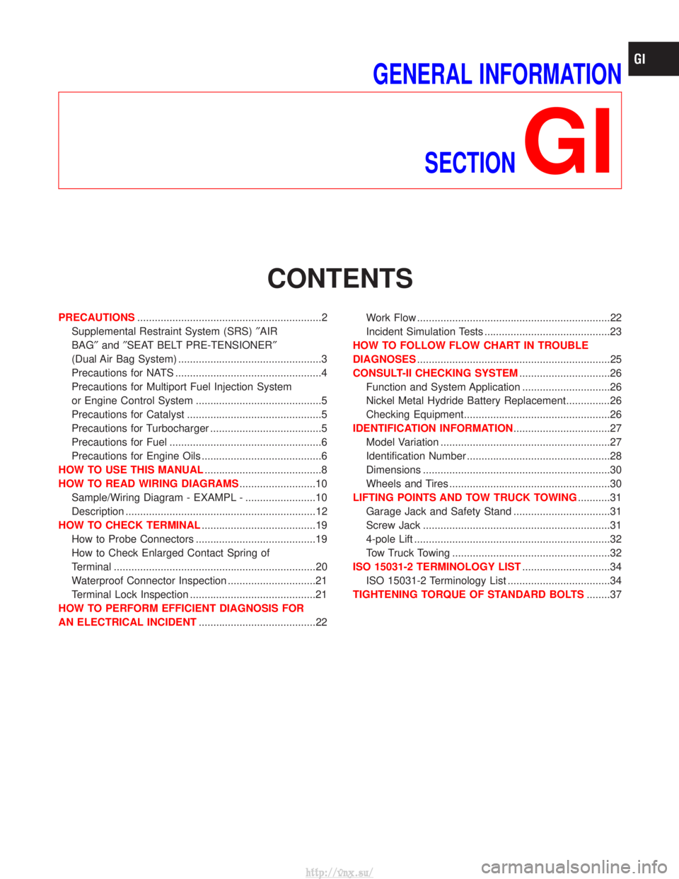
GENERAL INFORMATIONSECTION
GI
CONTENTS
PRECAUTIONS ...............................................................2
Supplemental Restraint System (SRS) ²AIR
BAG² and²SEAT BELT PRE-TENSIONER²
(Dual Air Bag System) .................................................3
Precautions for NATS ..................................................4
Precautions for Multiport Fuel Injection System
or Engine Control System ...........................................5
Precautions for Catalyst ..............................................5
Precautions for Turbocharger ......................................5
Precautions for Fuel ....................................................6
Precautions for Engine Oils .........................................6
HOW TO USE THIS MANUAL ........................................8
HOW TO READ WIRING DIAGRAMS ..........................10
Sample/Wiring Diagram - EXAMPL - ........................10
Description .................................................................12
HOW TO CHECK TERMINAL .......................................19
How to Probe Connectors .........................................19
How to Check Enlarged Contact Spring of
Terminal .....................................................................20
Waterproof Connector Inspection ..............................21
Terminal Lock Inspection ...........................................21
HOW TO PERFORM EFFICIENT DIAGNOSIS FOR
AN ELECTRICAL INCIDENT ........................................22 Work Flow ..................................................................22
Incident Simulation Tests ...........................................23
HOW TO FOLLOW FLOW CHART IN TROUBLE
DIAGNOSES ..................................................................25
CONSULT-II CHECKING SYSTEM ...............................26
Function and System Application ..............................26
Nickel Metal Hydride Battery Replacement...............26
Checking Equipment..................................................26
IDENTIFICATION INFORMATION .................................27
Model Variation ..........................................................27
Identification Number .................................................28
Dimensions ................................................................30
Wheels and Tires .......................................................30
LIFTING POINTS AND TOW TRUCK TOWING ...........31
Garage Jack and Safety Stand .................................31
Screw Jack ................................................................31
4-pole Lift ...................................................................32
Tow Truck Towing ......................................................32
ISO 15031-2 TERMINOLOGY LIST ..............................34
ISO 15031-2 Terminology List ...................................34
TIGHTENING TORQUE OF STANDARD BOLTS ........37
http://vnx.su/
Page 33 of 1833
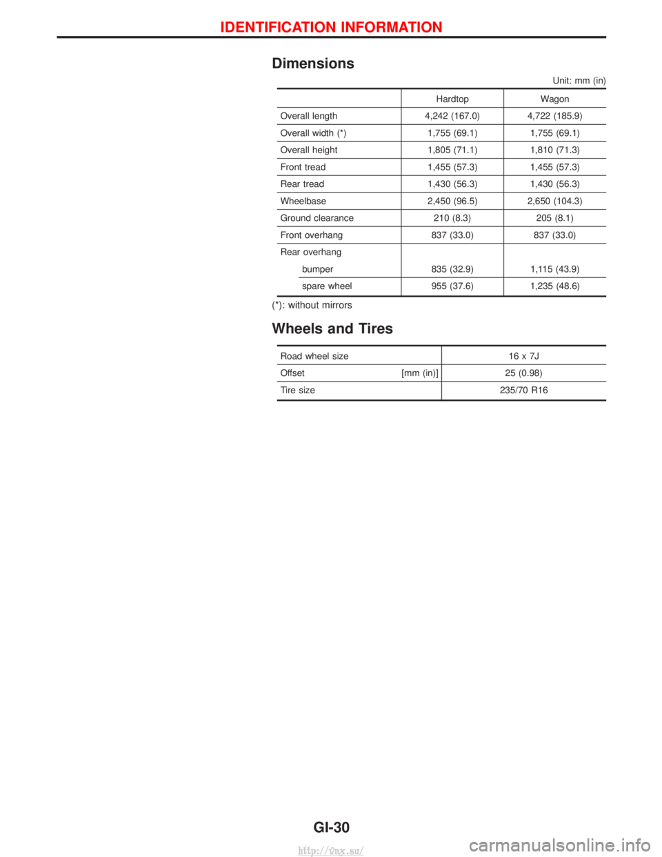
Dimensions
Unit: mm (in)
HardtopWagon
Overall length 4,242 (167.0) 4,722 (185.9)
Overall width (*) 1,755 (69.1) 1,755 (69.1)
Overall height 1,805 (71.1) 1,810 (71.3)
Front tread 1,455 (57.3) 1,455 (57.3)
Rear tread 1,430 (56.3) 1,430 (56.3)
Wheelbase 2,450 (96.5) 2,650 (104.3)
Ground clearance 210 (8.3) 205 (8.1)
Front overhang 837 (33.0) 837 (33.0)
Rear overhang bumper 835 (32.9) 1,115 (43.9)
spare wheel 955 (37.6) 1,235 (48.6)
(*): without mirrors
Wheels and Tires
Road wheel size 16 x 7J
Offset [mm (in)]25 (0.98)
Tire size 235/70 R16
IDENTIFICATION INFORMATION
GI-30
http://vnx.su/
Page 45 of 1833
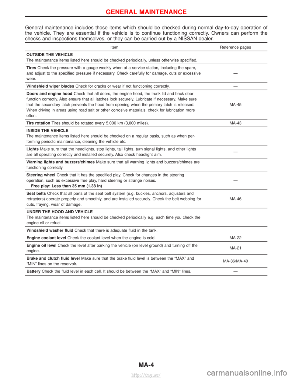
General maintenance includes those items which should be checked during normal day-to-day operation of
the vehicle. They are essential if the vehicle is to continue functioning correctly. Owners can perform the
checks and inspections themselves, or they can be carried out by a NISSAN dealer.
ItemReference pages
OUTSIDE THE VEHICLE
The maintenance items listed here should be checked periodically, unless otherwise specified.
Tires Check the pressure with a gauge weekly when at a service station, including the spare,
and adjust to the specified pressure if necessary. Check carefully for damage, cuts or excessive
wear. Ð
Windshield wiper blades Check for cracks or wear if not functioning correctly. Ð
Doors and engine hood Check that all doors, the engine hood, the trunk lid and back door
function correctly. Also ensure that all latches lock securely. Lubricate if necessary. Make sure
that the secondary latch prevents the hood from opening when the primary latch is released.
When driving in areas using road salt or other corrosive materials, check for lubrication more
often. MA-45
Tire rotation Tires should be rotated every 5,000 km (3,000 miles). MA-43
INSIDE THE VEHICLE
The maintenance items listed here should be checked on a regular basis, such as when per-
forming periodic maintenance, cleaning the vehicle etc.
Lights Make sure that the headlights, stop lights, tail lights, turn signal lights, and other lights
are all operating correctly and installed securely. Also check headlight aim. Ð
Warning lights and buzzers/chimes Make sure that all warning lights and buzzers/chimes are
functioning correctly. Ð
Steering wheel Check that it has the specified play. Check for changes in the steering
operation, such as excessive free play, hard steering or strange noises. Free play: Less than 35 mm (1.38 in) Ð
Seat belts Check that all parts of the seat belt system (e.g. buckles, anchors, adjusters and
retractors) operate properly and smoothly, and are installed securely. Check the belt webbing for
cuts, fraying, wear of damage. MA-46
UNDER THE HOOD AND VEHICLE
The maintenance items listed here should be checked periodically e.g. each time you check the
engine oil or refuel.
Windshield washer fluid Check that there is adequate fluid in the tank.
Engine coolant level Check the coolant level when the engine is cold. MA-22
Engine oil level Check the level after parking the vehicle (on level ground) and turning off the
engine. MA-21
Brake and clutch fluid level Make sure that the brake fluid level is between the ªMAXº and
ªMINº lines on the reservoir. MA-36/MA-40
Battery Check the fluid level in each cell. It should be between the ªMAXº and ªMINº lines. Ð
GENERAL MAINTENANCE
MA-4
http://vnx.su/
Page 1113 of 1833
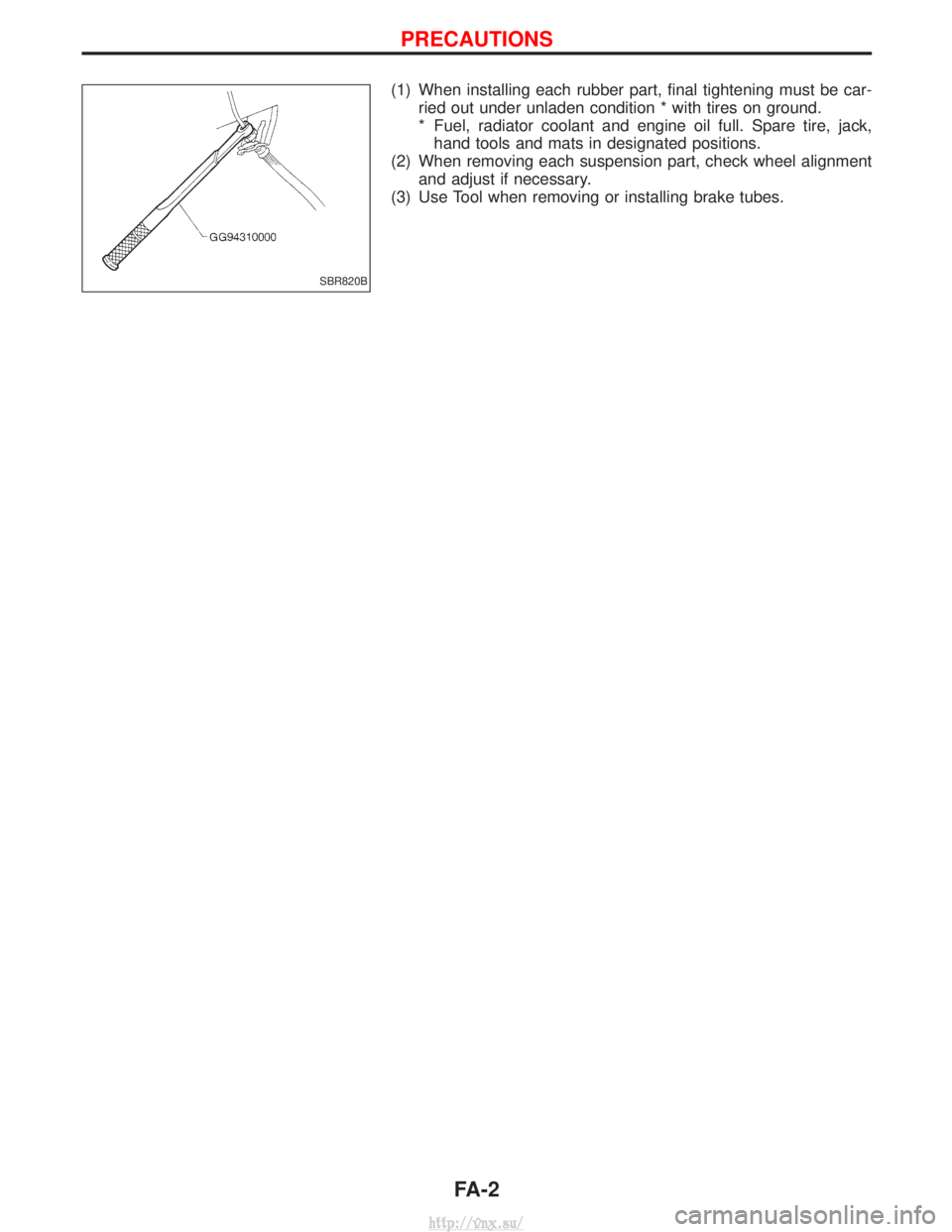
(1) When installing each rubber part, final tightening must be car-ried out under unladen condition * with tires on ground.
* Fuel, radiator coolant and engine oil full. Spare tire, jack,hand tools and mats in designated positions.
(2) When removing each suspension part, check wheel alignment and adjust if necessary.
(3) Use Tool when removing or installing brake tubes.
SBR820B
PRECAUTIONS
FA-2
http://vnx.su/
Page 1119 of 1833
Front Wheel Alignment
Before checking front wheel alignment, be sure to make a prelimi-
nary inspection.
PRELIMINARY INSPECTION
1. Check the tires for wear and proper inflation.
2. Check the wheel runout.Wheel runout:Refer to SDS, FA-39.
3. Check the front wheel bearings for looseness.
4. Check the front suspension for looseness.
5. Check the steering linkage for looseness.
6. Check that the front shock absorbers work properly by using the standard bounce test.
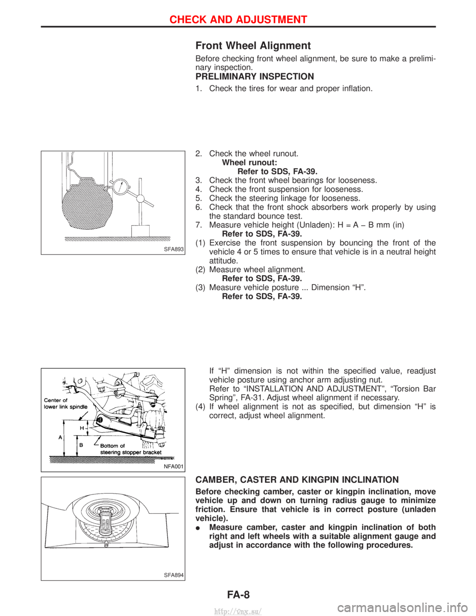
7. Measure vehicle height (Unladen): H = A þ B mm (in) Refer to SDS, FA-39.
(1) Exercise the front suspension by bouncing the front of the vehicle 4 or 5 times to ensure that vehicle is in a neutral height
attitude.
(2) Measure wheel alignment. Refer to SDS, FA-39.
(3) Measure vehicle posture ... Dimension ªHº. Refer to SDS, FA-39.
If ªHº dimension is not within the specified value, readjust
vehicle posture using anchor arm adjusting nut.
Refer to ªINSTALLATION AND ADJUSTMENTº, ªTorsion Bar
Springº, FA-31. Adjust wheel alignment if necessary.
(4) If wheel alignment is not as specified, but dimension ªHº is correct, adjust wheel alignment.
CAMBER, CASTER AND KINGPIN INCLINATION
Before checking camber, caster or kingpin inclination, move
vehicle up and down on turning radius gauge to minimize
friction. Ensure that vehicle is in correct posture (unladen
vehicle).
IMeasure camber, caster and kingpin inclination of both
right and left wheels with a suitable alignment gauge and
adjust in accordance with the following procedures.
SFA893
NFA001
SFA894
CHECK AND ADJUSTMENT
FA-8
http://vnx.su/
Page 1127 of 1833
qA
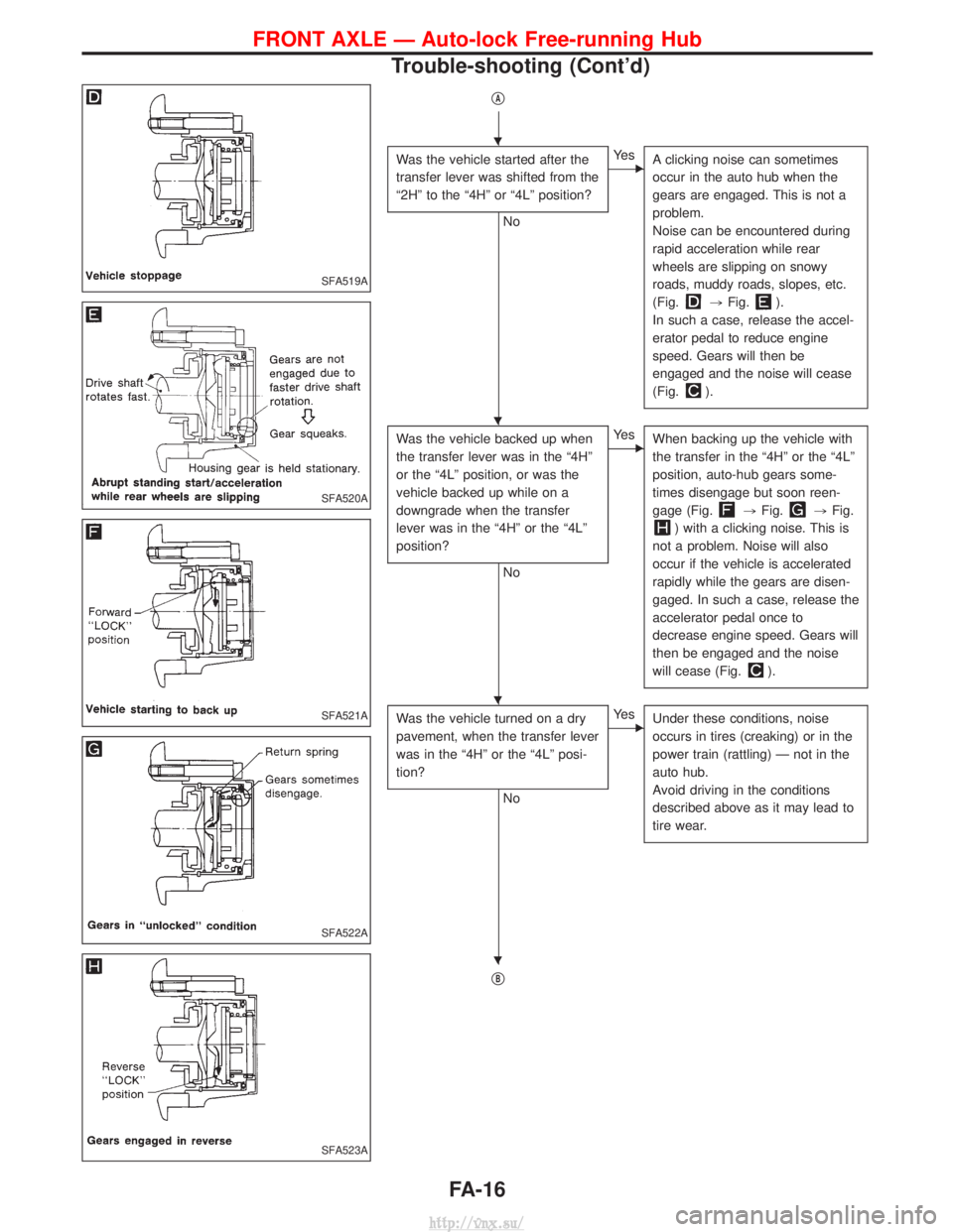
Was the vehicle started after the
transfer lever was shifted from the
ª2Hº to the ª4Hº or ª4Lº position?
No
EYe sA clicking noise can sometimes
occur in the auto hub when the
gears are engaged. This is not a
problem.
Noise can be encountered during
rapid acceleration while rear
wheels are slipping on snowy
roads, muddy roads, slopes, etc.
(Fig.
,Fig.).
In such a case, release the accel-
erator pedal to reduce engine
speed. Gears will then be
engaged and the noise will cease
(Fig.
).
Was the vehicle backed up when
the transfer lever was in the ª4Hº
or the ª4Lº position, or was the
vehicle backed up while on a
downgrade when the transfer
lever was in the ª4Hº or the ª4Lº
position?
No
EYe s When backing up the vehicle with
the transfer in the ª4Hº or the ª4Lº
position, auto-hub gears some-
times disengage but soon reen-
gage (Fig.
,Fig.,Fig.
) with a clicking noise. This is
not a problem. Noise will also
occur if the vehicle is accelerated
rapidly while the gears are disen-
gaged. In such a case, release the
accelerator pedal once to
decrease engine speed. Gears will
then be engaged and the noise
will cease (Fig.
).
Was the vehicle turned on a dry
pavement, when the transfer lever
was in the ª4Hº or the ª4Lº posi-
tion?
No
EYe s Under these conditions, noise
occurs in tires (creaking) or in the
power train (rattling) Ð not in the
auto hub.
Avoid driving in the conditions
described above as it may lead to
tire wear.
qB
SFA519A
SFA520A
SFA521A
SFA522A
SFA523A
H
H
H
H
FRONT AXLE Ð Auto-lock Free-running Hub
Trouble-shooting (Cont'd)
FA-16
http://vnx.su/
Page 1143 of 1833
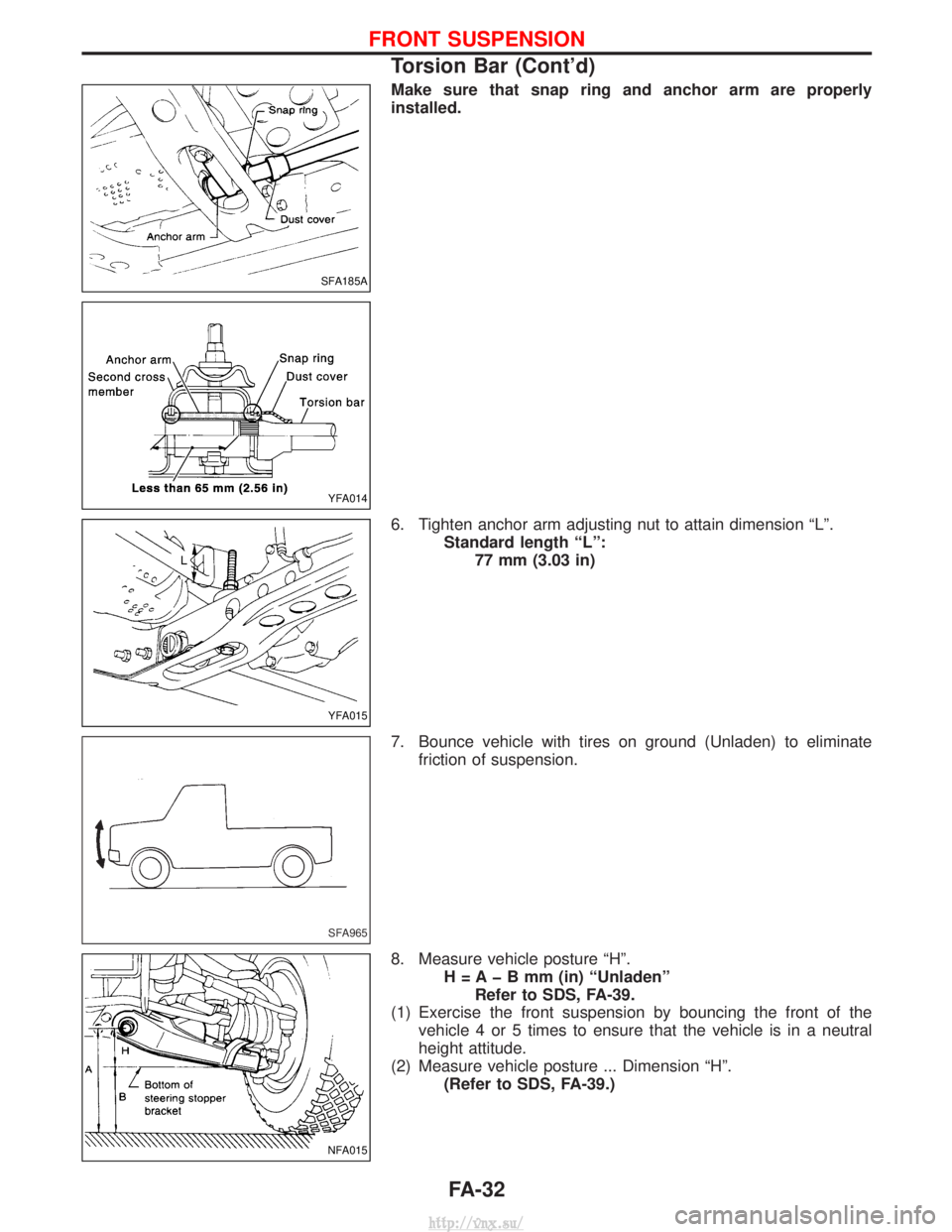
Make sure that snap ring and anchor arm are properly
installed.
6. Tighten anchor arm adjusting nut to attain dimension ªLº.Standard length ªLº:77 mm (3.03 in)
7. Bounce vehicle with tires on ground (Unladen) to eliminate friction of suspension.
8. Measure vehicle posture ªHº. H = A þ B mm (in) ªUnladenºRefer to SDS, FA-39.
(1) Exercise the front suspension by bouncing the front of the vehicle 4 or 5 times to ensure that the vehicle is in a neutral
height attitude.
(2) Measure vehicle posture ... Dimension ªHº. (Refer to SDS, FA-39.)
SFA185A
YFA014
YFA015
SFA965
NFA015
FRONT SUSPENSION
Torsion Bar (Cont'd)
FA-32
http://vnx.su/
Page 1145 of 1833
INSTALLATION
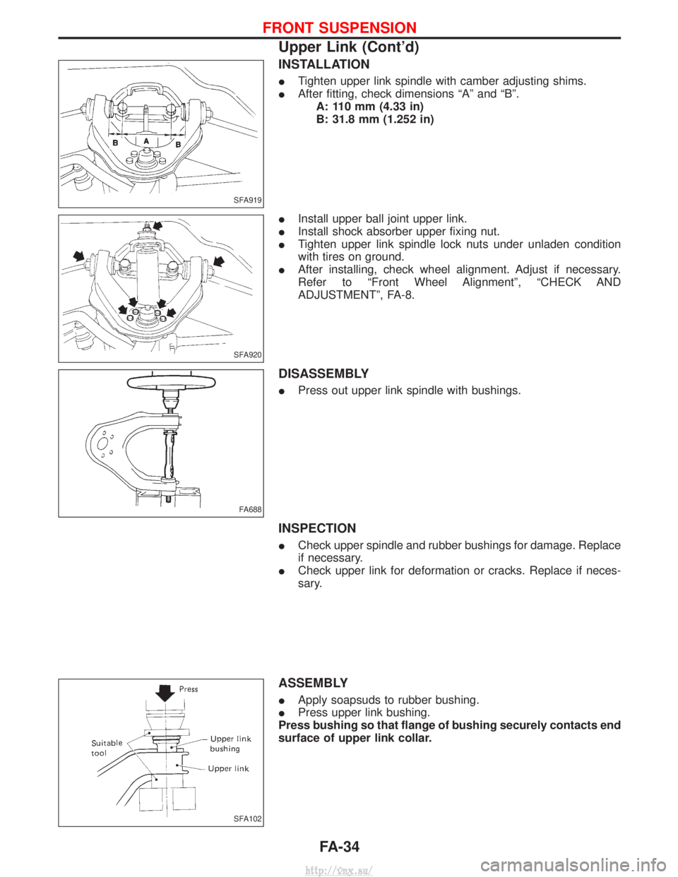
ITighten upper link spindle with camber adjusting shims.
I After fitting, check dimensions ªAº and ªBº.
A: 110 mm (4.33 in)
B: 31.8 mm (1.252 in)
I Install upper ball joint upper link.
I Install shock absorber upper fixing nut.
I Tighten upper link spindle lock nuts under unladen condition
with tires on ground.
I After installing, check wheel alignment. Adjust if necessary.
Refer to ªFront Wheel Alignmentº, ªCHECK AND
ADJUSTMENTº, FA-8.
DISASSEMBLY
IPress out upper link spindle with bushings.
INSPECTION
ICheck upper spindle and rubber bushings for damage. Replace
if necessary.
I Check upper link for deformation or cracks. Replace if neces-
sary.
ASSEMBLY
IApply soapsuds to rubber bushing.
I Press upper link bushing.
Press bushing so that flange of bushing securely contacts end
surface of upper link collar.
SFA919
SFA920
FA688
SFA102
FRONT SUSPENSION
Upper Link (Cont'd)
FA-34
http://vnx.su/
Page 1153 of 1833
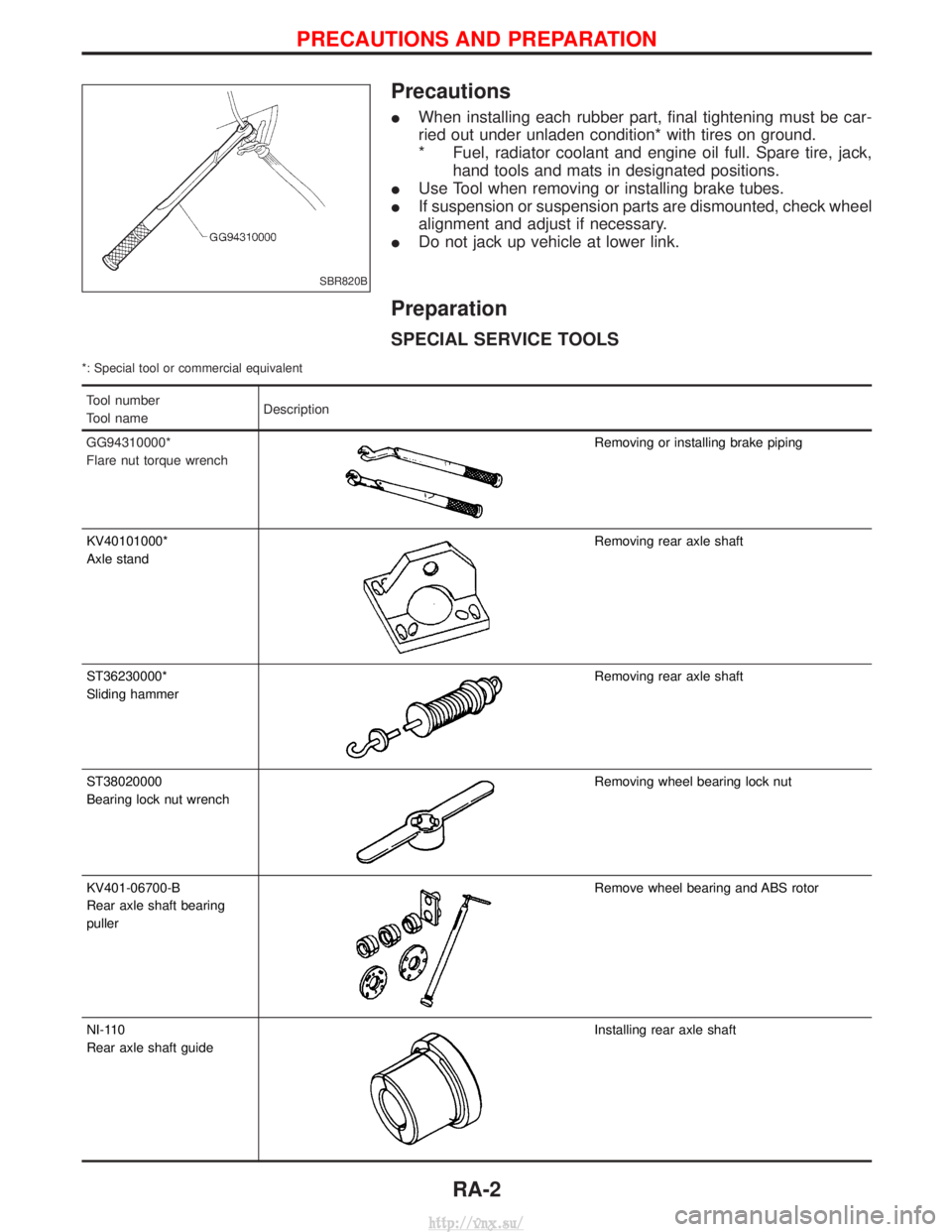
Precautions
IWhen installing each rubber part, final tightening must be car-
ried out under unladen condition* with tires on ground.
* Fuel, radiator coolant and engine oil full. Spare tire, jack,
hand tools and mats in designated positions.
I Use Tool when removing or installing brake tubes.
I If suspension or suspension parts are dismounted, check wheel
alignment and adjust if necessary.
I Do not jack up vehicle at lower link.
Preparation
SPECIAL SERVICE TOOLS
*: Special tool or commercial equivalent
Tool number
Tool name Description
GG94310000*
Flare nut torque wrench
Removing or installing brake piping
KV40101000*
Axle stand
Removing rear axle shaft
ST36230000*
Sliding hammer
Removing rear axle shaft
ST38020000
Bearing lock nut wrench
Removing wheel bearing lock nut
KV401-06700-B
Rear axle shaft bearing
puller
Remove wheel bearing and ABS rotor
NI-110
Rear axle shaft guide
Installing rear axle shaft
SBR820B
PRECAUTIONS AND PREPARATION
RA-2
http://vnx.su/
Page 1163 of 1833
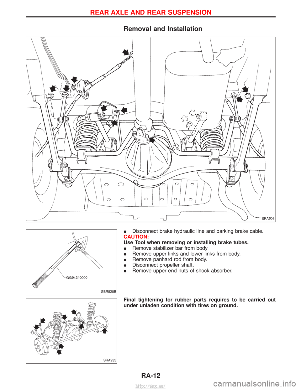
Removal and Installation
IDisconnect brake hydraulic line and parking brake cable.
CAUTION:
Use Tool when removing or installing brake tubes.
I Remove stabilizer bar from body
I Remove upper links and lower links from body.
I Remove panhard rod from body.
I Disconnect propeller shaft.
I Remove upper end nuts of shock absorber.
Final tightening for rubber parts requires to be carried out
under unladen condition with tires on ground.
SRA906
SBR820B
SRA935
REAR AXLE AND REAR SUSPENSION
RA-12
http://vnx.su/