turn signal relay NISSAN TERRANO 2004 Service Repair Manual
[x] Cancel search | Manufacturer: NISSAN, Model Year: 2004, Model line: TERRANO, Model: NISSAN TERRANO 2004Pages: 1833, PDF Size: 53.42 MB
Page 297 of 1833
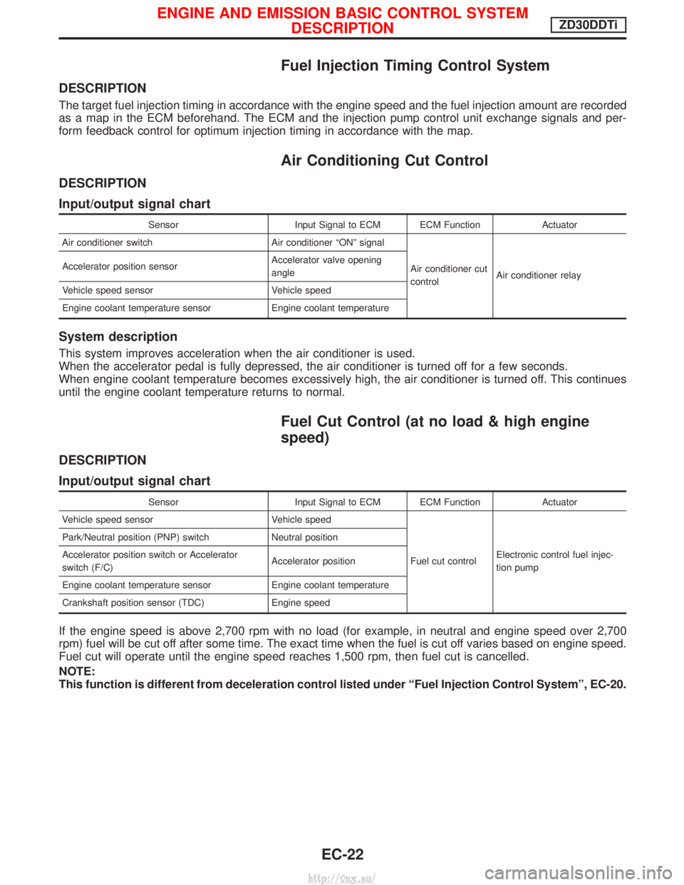
Fuel Injection Timing Control System
DESCRIPTION
The target fuel injection timing in accordance with the engine speed and the fuel injection amount are recorded
as a map in the ECM beforehand. The ECM and the injection pump control unit exchange signals and per-
form feedback control for optimum injection timing in accordance with the map.
Air Conditioning Cut Control
DESCRIPTION
Input/output signal chart
SensorInput Signal to ECM ECM Function Actuator
Air conditioner switch Air conditioner ªONº signal
Air conditioner cut
controlAir conditioner relay
Accelerator position sensor
Accelerator valve opening
angle
Vehicle speed sensor Vehicle speed
Engine coolant temperature sensor Engine coolant temperature
System description
This system improves acceleration when the air conditioner is used.
When the accelerator pedal is fully depressed, the air conditioner is turned off for a few seconds.
When engine coolant temperature becomes excessively high, the air conditioner is turned off. This continues
until the engine coolant temperature returns to normal.
Fuel Cut Control (at no load & high engine
speed)
DESCRIPTION
Input/output signal chart
SensorInput Signal to ECM ECM Function Actuator
Vehicle speed sensor Vehicle speed
Fuel cut controlElectronic control fuel injec-
tion pump
Park/Neutral position (PNP) switch
Neutral position
Accelerator position switch or Accelerator
switch (F/C) Accelerator position
Engine coolant temperature sensor Engine coolant temperature
Crankshaft position sensor (TDC) Engine speed
If the engine speed is above 2,700 rpm with no load (for example, in neutral and engine speed over 2,700
rpm) fuel will be cut off after some time. The exact time when the fuel is cut off varies based on engine speed.
Fuel cut will operate until the engine speed reaches 1,500 rpm, then fuel cut is cancelled.
NOTE:
This function is different from deceleration control listed under ªFuel Injection Control Systemº, EC-20.
ENGINE AND EMISSION BASIC CONTROL SYSTEM
DESCRIPTIONZD30DDTi
EC-22
http://vnx.su/
Page 345 of 1833
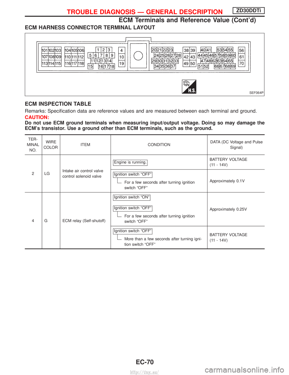
ECM HARNESS CONNECTOR TERMINAL LAYOUT
ECM INSPECTION TABLE
Remarks: Specification data are reference values and are measured between each terminal and ground.
CAUTION:
Do not use ECM ground terminals when measuring input/output voltage. Doing so may damage the
ECM's transistor. Use a ground other than ECM terminals, such as the ground.
TER-
MINAL NO. WIRE
COLOR ITEM CONDITION DATA (DC Voltage and Pulse
Signal)
2LG Intake air control valve
control solenoid valve Engine is running.
BATTERY VOLTAGE
(11 - 14V)
Ignition switch ªOFFº
For a few seconds after turning ignition
switch ªOFFº Approximately 0.1V
4 G ECM relay (Self-shutoff) Ignition switch ªONº
Ignition switch ªOFFº
For a few seconds after turning ignition
switch ªOFFº
Approximately 0.25V
Ignition switch ªOFFº
More than a few seconds after turning igni-
tion switch ªOFFº BATTERY VOLTAGE
(11 - 14V)
SEF064P
TROUBLE DIAGNOSIS Ð GENERAL DESCRIPTIONZD30DDTi
ECM Terminals and Reference Value (Cont'd)
EC-70
http://vnx.su/
Page 391 of 1833

6 CHECK COOLING FAN GROUND CIRCUIT FOR OPEN AND SHORT
1. Turn ignition switch ªOFFº.
2. Disconnect cooling fan motor harness connector.
MEC024E
3. Check harness continuity as follows. Refer to Wiring Diagram.
MTBL13224. Also check harness for short to ground and short to power.OK or NG
OK EGO TO 8.
NG EGO TO 7.
7 DETECT MALFUNCTIONING PART
Check the following.
IHarness connectors M785, F67 (M/T models)
I Harness for open or short between cooling fan relay and cooling fan motor
I Harness for open or short between cooling fan relay and condenser
I Harness for open or short between cooling fan motor and ground
I Harness for open or short between condenser and ground
ERepair open circuit or short to ground or short to power in harness or connectors.
8 CHECK COOLING FAN OUTPUT SIGNAL CIRCUIT FOR OPEN AND SHORT
1. Disconnect ECM harness connector.
2. Check harness continuity between ECM terminal 14 and cooling fan relay terminal 1. Refer to Wiring Diagram.
Continuity should exist.
3. Also check harness for short to ground and short to power.
OK or NG
OK EGO TO 10.
NG EGO TO 9.
9 DETECT MALFUNCTIONING PART
Check the following.
IHarness connectors M787, F66
I Harness for open or short between cooling fan relay and ECM
ERepair open circuit or short to ground or short to power in harness or connectors.
DTC 0208 OVER HEATZD30DDTi
Diagnostic Procedure (Cont'd)
EC-116
http://vnx.su/
Page 489 of 1833
ECM Terminals and Reference Value
Specification data are reference values and are measured between each terminal and ground.
CAUTION:
Do not use ECM ground terminals when measuring input/output voltage. Doing so may damage the
ECM's transistor. Use a ground other than ECM terminals, such as the ground.
TER-
MINAL NO. WIRE
COLOR ITEM CONDITION DATA (DC Voltage)
4 G ECM relay (Self-shutoff) Ignition switch ªONº
Ignition switch ªOFFº
For a few seconds after turning ignition switch
ªOFFº
Approximately 0.25V
Ignition switch ªOFFº
More than a few seconds after turning ignition
switch ªOFFº BATTERY VOLTAGE
(11 - 14V)
38 B/W Ignition switch Ignition switch ªOFFº
0V
Ignition switch ªONº
BATTERY VOLTAGE
(11 - 14V)
56
61
11 6 B/W
B/W
B/W
Power supply for ECM Ignition switch ªONº
BATTERY VOLTAGE
(11 - 14V)
On Board Diagnosis Logic
Malfunction is detected when ....
Check Items (Possible Cause)
I An irregular voltage signal from the ECM relay is sent to ECM. IHarness or connectors
(ECM relay circuit is open or shorted.)
I ECM relay
DTC Confirmation Procedure
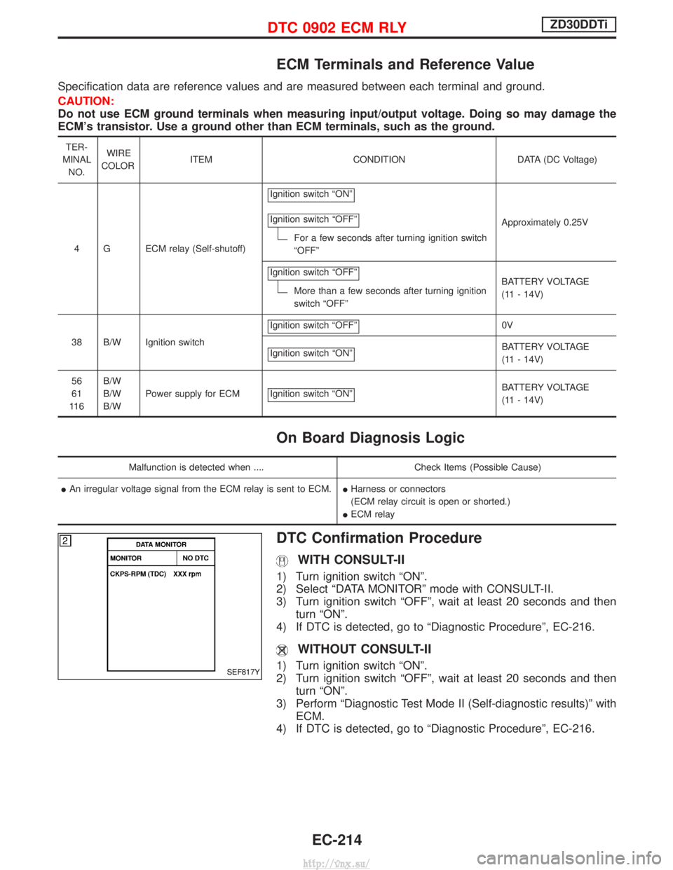
WITH CONSULT-II
1) Turn ignition switch ªONº.
2) Select ªDATA MONITORº mode with CONSULT-II.
3) Turn ignition switch ªOFFº, wait at least 20 seconds and then
turn ªONº.
4) If DTC is detected, go to ªDiagnostic Procedureº, EC-216.
WITHOUT CONSULT-II
1) Turn ignition switch ªONº.
2) Turn ignition switch ªOFFº, wait at least 20 seconds and then turn ªONº.
3) Perform ªDiagnostic Test Mode II (Self-diagnostic results)º with ECM.
4) If DTC is detected, go to ªDiagnostic Procedureº, EC-216.SEF817Y
DTC 0902 ECM RLYZD30DDTi
EC-214
http://vnx.su/
Page 491 of 1833

Diagnostic Procedure
1 CHECK ECM POWER SUPPLY CIRCUIT
1. Turn ignition switch ªOFFº.
2. Disconnect ECM relay.
MEC021E
3. Check voltage between ECM relay terminals 2, 3 and ground with CONSULT-II or tester.
MEC978DVoltage: Battery voltageOK or NG
OK EGO TO 3.
NG EGO TO 2.
2 DETECT MALFUNCTIONING PART
Check the following.
I10A fuse
I 15A fuse
I Harness for open and short between ECM relay and battery
ERepair open circuit or short to ground or short to power in harness or connectors.
3 CHECK ECM INPUT SIGNAL CIRCUIT FOR OPEN AND SHORT
1. Turn ignition switch ªOFFº.
2. Disconnect ECM harness connector.
3. Check harness continuity between ECM terminals 56, 61, 116 and ECM relay terminal 5. Refer to Wiring Diagram.
Continuity should exist.
4. Also check harness for short to ground and short to power.
OK or NG
OK EGO TO 5.
NG EGO TO 4.
DTC 0902 ECM RLYZD30DDTi
EC-216
http://vnx.su/
Page 509 of 1833
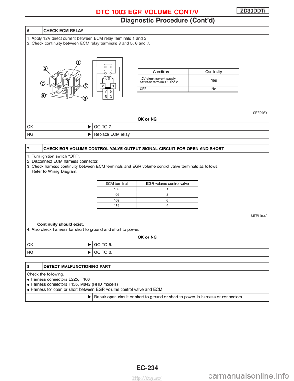
6 CHECK ECM RELAY
1. Apply 12V direct current between ECM relay terminals 1 and 2.
2. Check continuity between ECM relay terminals 3 and 5, 6 and 7.
SEF296X
OK or NG
OK EGO TO 7.
NG EReplace ECM relay.
7 CHECK EGR VOLUME CONTROL VALVE OUTPUT SIGNAL CIRCUIT FOR OPEN AND SHORT
1. Turn ignition switch ªOFFº.
2. Disconnect ECM harness connector.
3. Check harness continuity between ECM terminals and EGR volume control valve terminals as follows.
Refer to Wiring Diagram.
MTBL0442
Continuity should exist.
4. Also check harness for short to ground and short to power.
OK or NG
OK EGO TO 9.
NG EGO TO 8.
8 DETECT MALFUNCTIONING PART
Check the following.
IHarness connectors E225, F108
I Harness connectors F135, M842 (RHD models)
I Harness for open or short between EGR volume control valve and ECM
ERepair open circuit or short to ground or short to power in harness or connectors.
DTC 1003 EGR VOLUME CONT/VZD30DDTi
Diagnostic Procedure (Cont'd)
EC-234
http://vnx.su/
Page 519 of 1833
Description
SYSTEM DESCRIPTION
Sensor Input Signal to ECMECM
Function Actuator
Crankshaft position
sensor (TDC) Engine speed
Glow
control Glow lamp,
Glow relay "
Glow plugs
Engine coolant tem-
perature sensor Engine coolant tem-
perature
When engine coolant temperature is more than approximately 75ÉC
(167ÉF), the glow relay turns off, inactivating the quick-glow control
until coolant temperature drops below approximately 55ÉC (131ÉF).
When coolant temperature is lower than approximately 75ÉC
(167ÉF):
I
Ignition switch ON
After ignition switch has turned to ON, the glow relay turns ON
for a certain period of time in relation to engine coolant
temperature, allowing current to flow through glow plug.
I Cranking
The glow relay turns ON, allowing current to flow through glow
plug.
I Starting
After engine has started, current continues to flow through glow
plug (after-glow mode) for a certain period in relation to engine
coolant temperature.
When engine speed exceeds approximately 4,800 rpm, current
flow through glow plug is interrupted.
The glow indicator lamp turns ON for a certain period of time in
relation to engine coolant temperature at the time glow relay is
turned ON.
COMPONENT DESCRIPTION
Glow plug
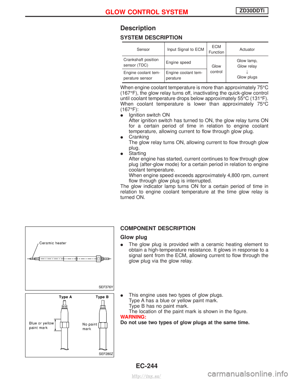
I The glow plug is provided with a ceramic heating element to
obtain a high-temperature resistance. It glows in response to a
signal sent from the ECM, allowing current to flow through the
glow plug via the glow relay.
I This engine uses two types of glow plugs.
Type A has a blue or yellow paint mark.
Type B has no paint mark.
The location of the paint mark is shown in the figure.
WARNING:
Do not use two types of glow plugs at the same time.
SEF376Y
SEF280Z
GLOW CONTROL SYSTEMZD30DDTi
EC-244
http://vnx.su/
Page 525 of 1833
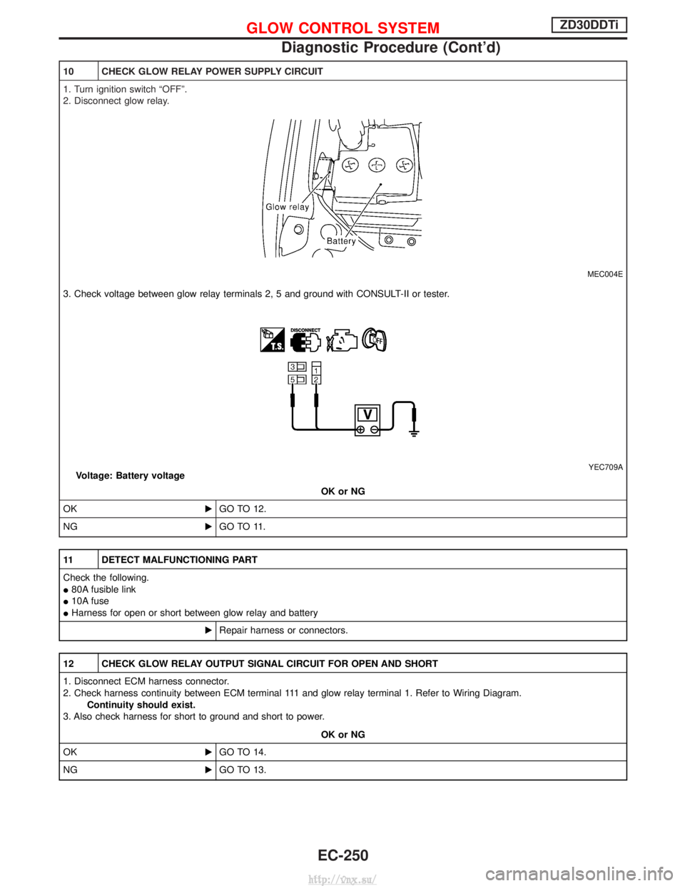
10 CHECK GLOW RELAY POWER SUPPLY CIRCUIT
1. Turn ignition switch ªOFFº.
2. Disconnect glow relay.
MEC004E
3. Check voltage between glow relay terminals 2, 5 and ground with CONSULT-II or tester.
YEC709AVoltage: Battery voltageOK or NG
OK EGO TO 12.
NG EGO TO 11.
11 DETECT MALFUNCTIONING PART
Check the following.
I80A fusible link
I 10A fuse
I Harness for open or short between glow relay and battery
ERepair harness or connectors.
12 CHECK GLOW RELAY OUTPUT SIGNAL CIRCUIT FOR OPEN AND SHORT
1. Disconnect ECM harness connector.
2. Check harness continuity between ECM terminal 111 and glow relay terminal 1. Refer to Wiring Diagram.
Continuity should exist.
3. Also check harness for short to ground and short to power.
OK or NG
OK EGO TO 14.
NG EGO TO 13.
GLOW CONTROL SYSTEMZD30DDTi
Diagnostic Procedure (Cont'd)
EC-250
http://vnx.su/
Page 538 of 1833
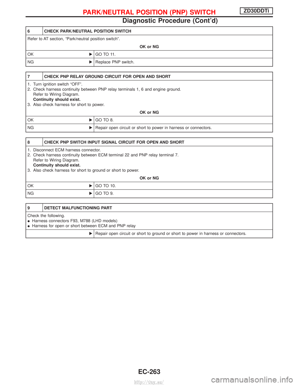
6 CHECK PARK/NEUTRAL POSITION SWITCH
Refer to AT section, ªPark/neutral position switchº.OK or NG
OK EGO TO 11.
NG EReplace PNP switch.
7 CHECK PNP RELAY GROUND CIRCUIT FOR OPEN AND SHORT
1. Turn ignition switch ªOFFº.
2. Check harness continuity between PNP relay terminals 1, 6 and engine ground.
Refer to Wiring Diagram.
Continuity should exist.
3. Also check harness for short to power.
OK or NG
OK EGO TO 8.
NG ERepair open circuit or short to power in harness or connectors.
8 CHECK PNP SWITCH INPUT SIGNAL CIRCUIT FOR OPEN AND SHORT
1. Disconnect ECM harness connector.
2. Check harness continuity between ECM terminal 22 and PNP relay terminal 7.
Refer to Wiring Diagram.
Continuity should exist.
3. Also check harness for short to ground or short to power.
OK or NG
OK EGO TO 10.
NG EGO TO 9.
9 DETECT MALFUNCTIONING PART
Check the following.
IHarness connectors F93, M788 (LHD models)
I Harness for open or short between ECM and PNP relay
ERepair open circuit or short to ground or short to power in harness or connectors.
PARK/NEUTRAL POSITION (PNP) SWITCHZD30DDTi
Diagnostic Procedure (Cont'd)
EC-263
http://vnx.su/
Page 562 of 1833
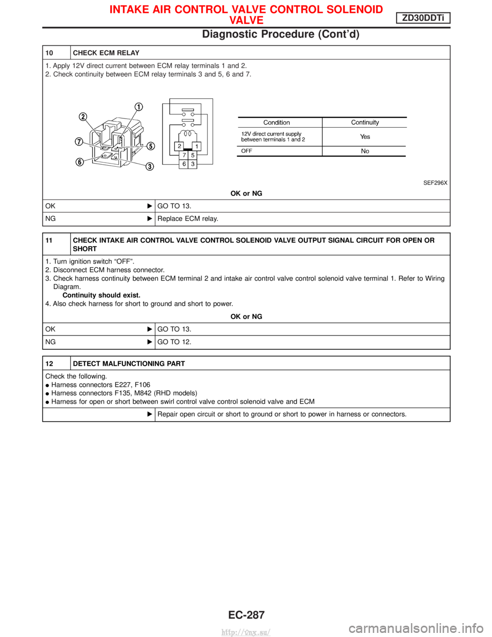
10 CHECK ECM RELAY
1. Apply 12V direct current between ECM relay terminals 1 and 2.
2. Check continuity between ECM relay terminals 3 and 5, 6 and 7.
SEF296X
OK or NG
OK EGO TO 13.
NG EReplace ECM relay.
11 CHECK INTAKE AIR CONTROL VALVE CONTROL SOLENOID VALVE OUTPUT SIGNAL CIRCUIT FOR OPEN OR
SHORT
1. Turn ignition switch ªOFFº.
2. Disconnect ECM harness connector.
3. Check harness continuity between ECM terminal 2 and intake air control valve control solenoid valve terminal 1. Refer to Wiring Diagram. Continuity should exist.
4. Also check harness for short to ground and short to power.
OK or NG
OK EGO TO 13.
NG EGO TO 12.
12 DETECT MALFUNCTIONING PART
Check the following.
IHarness connectors E227, F106
I Harness connectors F135, M842 (RHD models)
I Harness for open or short between swirl control valve control solenoid valve and ECM
ERepair open circuit or short to ground or short to power in harness or connectors.
INTAKE AIR CONTROL VALVE CONTROL SOLENOID
VA LV EZD30DDTi
Diagnostic Procedure (Cont'd)
EC-287
http://vnx.su/