drain bolt NISSAN TERRANO 2004 Service Repair Manual
[x] Cancel search | Manufacturer: NISSAN, Model Year: 2004, Model line: TERRANO, Model: NISSAN TERRANO 2004Pages: 1833, PDF Size: 53.42 MB
Page 42 of 1833
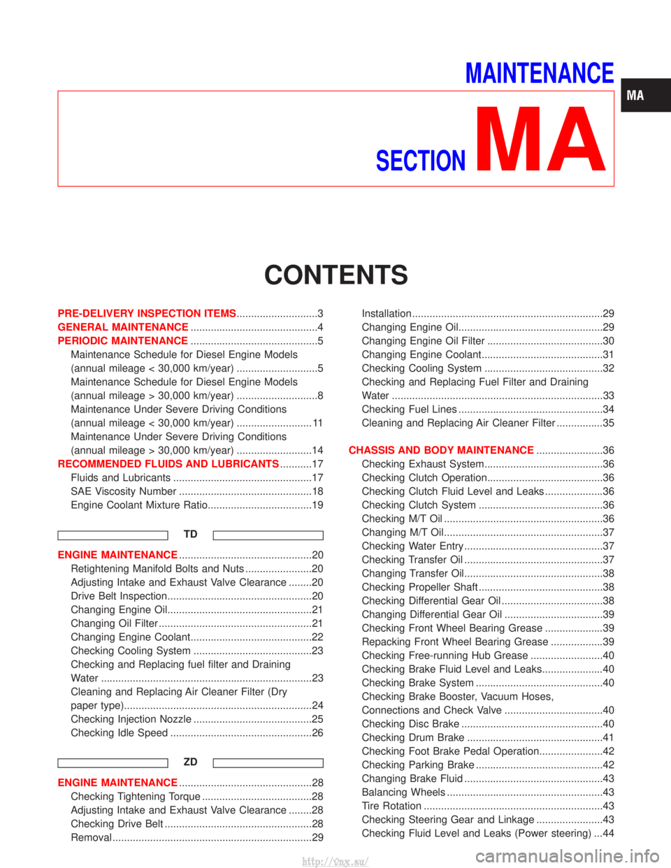
MAINTENANCE
SECTION
MA
CONTENTS
PRE-DELIVERY INSPECTION ITEMS ............................3
GENERAL MAINTENANCE ............................................4
PERIODIC MAINTENANCE ............................................5
Maintenance Schedule for Diesel Engine Models
(annual mileage < 30,000 km/year) ............................5
Maintenance Schedule for Diesel Engine Models
(annual mileage > 30,000 km/year) ............................8
Maintenance Under Severe Driving Conditions
(annual mileage < 30,000 km/year) .......................... 11
Maintenance Under Severe Driving Conditions
(annual mileage > 30,000 km/year) ..........................14
RECOMMENDED FLUIDS AND LUBRICANTS ...........17
Fluids and Lubricants ................................................17
SAE Viscosity Number ..............................................18
Engine Coolant Mixture Ratio....................................19
TD
ENGINE MAINTENANCE ..............................................20
Retightening Manifold Bolts and Nuts .......................20
Adjusting Intake and Exhaust Valve Clearance ........20
Drive Belt Inspection..................................................20
Changing Engine Oil..................................................21
Changing Oil Filter .....................................................21
Changing Engine Coolant..........................................22
Checking Cooling System .........................................23
Checking and Replacing fuel filter and Draining
Water ........................................................................\
.23
Cleaning and Replacing Air Cleaner Filter (Dry
paper type).................................................................24
Checking Injection Nozzle .........................................25
Checking Idle Speed .................................................26
ZD
ENGINE MAINTENANCE ..............................................28
Checking Tightening Torque ......................................28
Adjusting Intake and Exhaust Valve Clearance ........28
Checking Drive Belt ...................................................28
Removal .....................................................................29 Installation ..................................................................29
Changing Engine Oil..................................................29
Changing Engine Oil Filter ........................................30
Changing Engine Coolant..........................................31
Checking Cooling System .........................................32
Checking and Replacing Fuel Filter and Draining
Water ........................................................................\
.33
Checking Fuel Lines ..................................................34
Cleaning and Replacing Air Cleaner Filter ................35
CHASSIS AND BODY MAINTENANCE .......................36
Checking Exhaust System.........................................36
Checking Clutch Operation........................................36
Checking Clutch Fluid Level and Leaks ....................36
Checking Clutch System ...........................................36
Checking M/T Oil .......................................................36
Changing M/T Oil.......................................................37
Checking Water Entry ................................................37
Checking Transfer Oil ................................................37
Changing Transfer Oil................................................38
Checking Propeller Shaft ...........................................38
Checking Differential Gear Oil ...................................38
Changing Differential Gear Oil ..................................39
Checking Front Wheel Bearing Grease ....................39
Repacking Front Wheel Bearing Grease ..................39
Checking Free-running Hub Grease .........................40
Checking Brake Fluid Level and Leaks.....................40
Checking Brake System ............................................40
Checking Brake Booster, Vacuum Hoses,
Connections and Check Valve ..................................40
Checking Disc Brake .................................................40
Checking Drum Brake ...............................................41
Checking Foot Brake Pedal Operation......................42
Checking Parking Brake ............................................42
Changing Brake Fluid ................................................43
Balancing Wheels ......................................................43
Tire Rotation ..............................................................43
Checking Steering Gear and Linkage .......................43
Checking Fluid Level and Leaks (Power steering) ...44
http://vnx.su/
Page 70 of 1833
Removal
WATER PUMP, ALTERNATOR AND AIR CONDITIONER
BELT
1. Remove radiator shroud.
2. Contract and hold the auto tensioner using the following proce-dure.
a. Securely hold the 19 mm (0.75 in) hexagonal portion A of auto tensioner with a closed wrench.
I Preferably use a tool with a handhold of 500 mm (19.69 in) or
more in length.
I No bolts or nuts are required to be loosened during the opera-
tion.
b. Turn the hexagonal portion A in the direction shown by the arrow to contract the damper unit of the auto tensioner.
CAUTION:
I Because the tensioner has a high tension, it shall be
securely held and turned with a closed wrench.
I Because the hexagonal portion A of the tensioner is made
of aluminum and may be damaged by sudden input, turn
it slowly according to the contraction of the damper unit.
3. Remove the belt from the alternator pulley first, and then remove it from the other pulleys.
I If the tensioner is not held firmly, your finger may get caught
between the belt and the pulleys. Confirm the holding of the
tensioner, and then hold the belt side in the place away from
the pulleys to attach or remove the belt, paying attention to
prevent your finger from being caught.
CAUTION:
I When handling the belt, pay attention to prevent the oil or
coolant from adhering to the belt.
I Do not distort or bend the belt intensively.
Installation
IInstall the belt in the reverse order of removal.
I After installation of the belt, confirm that the belt engages the
pulleys securely.
I Depending on the engagement between the belt and the idler
pulley, noise (belt noise) may be heard when the engine is
started just after installation. This noise will stop with time.
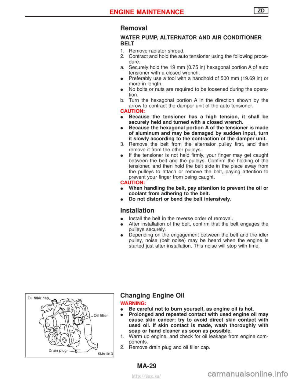
Changing Engine Oil
WARNING:
IBe careful not to burn yourself, as engine oil is hot.
I Prolonged and repeated contact with used engine oil may
cause skin cancer; try to avoid direct skin contact with
used oil. If skin contact is made, wash thoroughly with
soap or hand cleaner as soon as possible.
1. Warm up engine, and check for oil leakage from engine com- ponents.
2. Remove drain plug and oil filler cap.
SMA101D
ENGINE MAINTENANCEZD
MA-29
http://vnx.su/
Page 113 of 1833
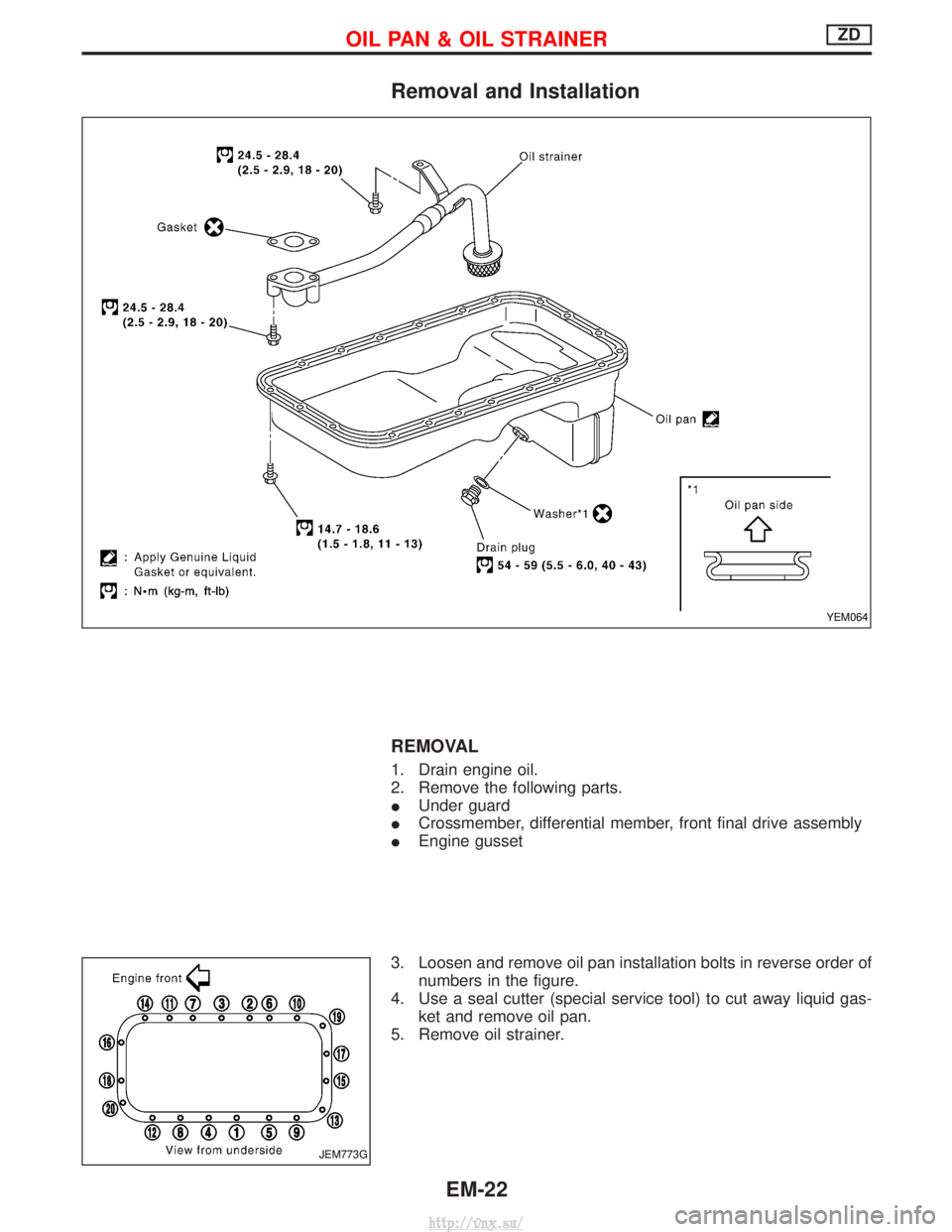
Removal and Installation
REMOVAL
1. Drain engine oil.
2. Remove the following parts.
IUnder guard
I Crossmember, differential member, front final drive assembly
I Engine gusset
3. Loosen and remove oil pan installation bolts in reverse order of numbers in the figure.
4. Use a seal cutter (special service tool) to cut away liquid gas- ket and remove oil pan.
5. Remove oil strainer.
YEM064
JEM773G
OIL PAN & OIL STRAINERZD
EM-22
http://vnx.su/
Page 117 of 1833
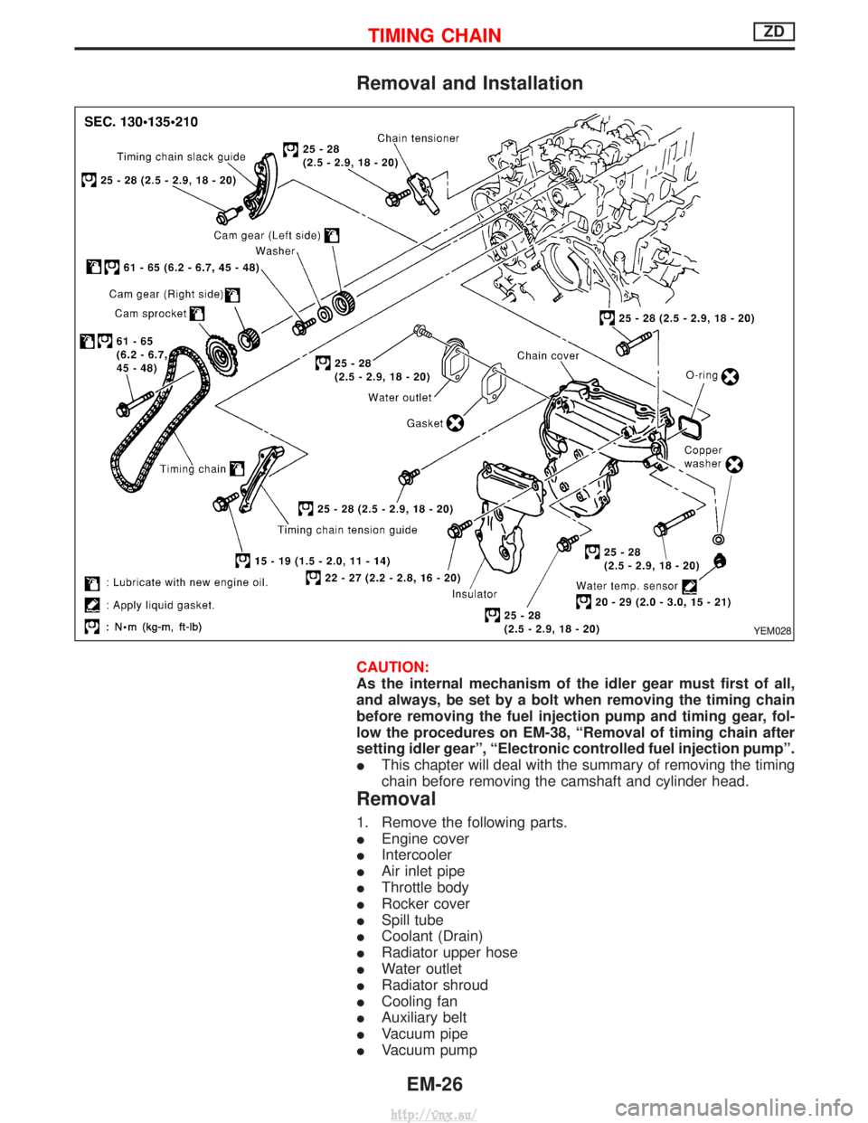
Removal and Installation
CAUTION:
As the internal mechanism of the idler gear must first of all,
and always, be set by a bolt when removing the timing chain
before removing the fuel injection pump and timing gear, fol-
low the procedures on EM-38, ªRemoval of timing chain after
setting idler gearº, ªElectronic controlled fuel injection pumpº.
IThis chapter will deal with the summary of removing the timing
chain before removing the camshaft and cylinder head.
Removal
1. Remove the following parts.
IEngine cover
I Intercooler
I Air inlet pipe
I Throttle body
I Rocker cover
I Spill tube
I Coolant (Drain)
I Radiator upper hose
I Water outlet
I Radiator shroud
I Cooling fan
I Auxiliary belt
I Vacuum pipe
I Vacuum pump
YEM028
TIMING CHAINZD
EM-26
http://vnx.su/
Page 143 of 1833
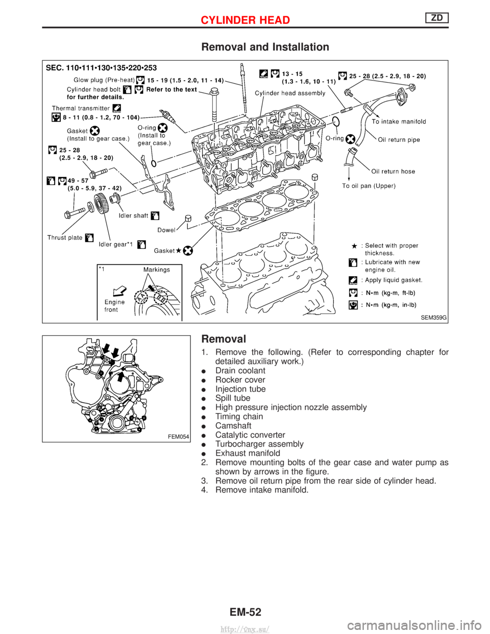
Removal and Installation
Removal
1. Remove the following. (Refer to corresponding chapter fordetailed auxiliary work.)
I Drain coolant
I Rocker cover
I Injection tube
I Spill tube
I High pressure injection nozzle assembly
I Timing chain
I Camshaft
I Catalytic converter
I Turbocharger assembly
I Exhaust manifold
2. Remove mounting bolts of the gear case and water pump as shown by arrows in the figure.
3. Remove oil return pipe from the rear side of cylinder head.
4. Remove intake manifold.
SEM359G
FEM054
CYLINDER HEADZD
EM-52
http://vnx.su/
Page 159 of 1833
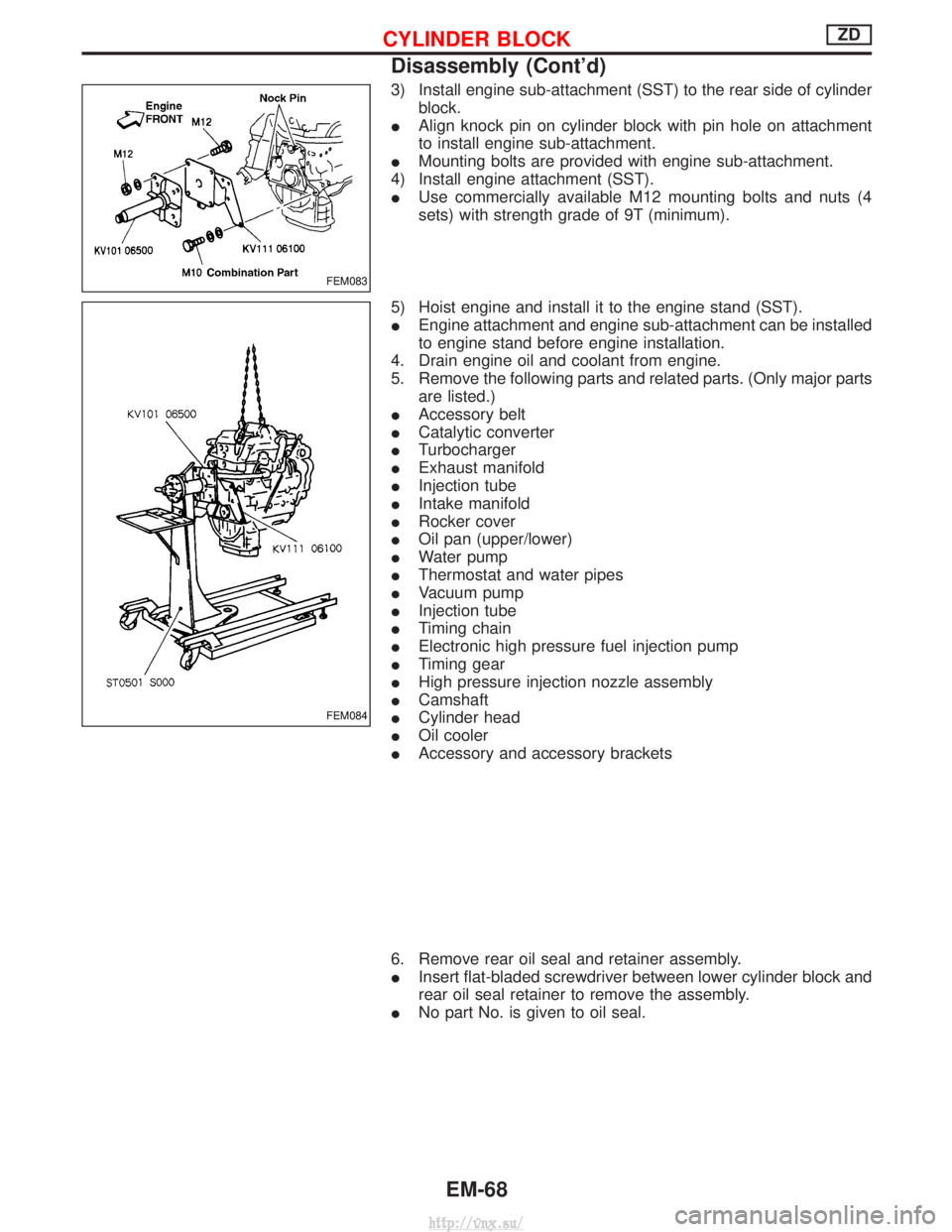
3) Install engine sub-attachment (SST) to the rear side of cylinderblock.
I Align knock pin on cylinder block with pin hole on attachment
to install engine sub-attachment.
I Mounting bolts are provided with engine sub-attachment.
4) Install engine attachment (SST).
I Use commercially available M12 mounting bolts and nuts (4
sets) with strength grade of 9T (minimum).
5) Hoist engine and install it to the engine stand (SST).
I Engine attachment and engine sub-attachment can be installed
to engine stand before engine installation.
4. Drain engine oil and coolant from engine.
5. Remove the following parts and related parts. (Only major parts are listed.)
I Accessory belt
I Catalytic converter
I Turbocharger
I Exhaust manifold
I Injection tube
I Intake manifold
I Rocker cover
I Oil pan (upper/lower)
I Water pump
I Thermostat and water pipes
I Vacuum pump
I Injection tube
I Timing chain
I Electronic high pressure fuel injection pump
I Timing gear
I High pressure injection nozzle assembly
I Camshaft
I Cylinder head
I Oil cooler
I Accessory and accessory brackets
6. Remove rear oil seal and retainer assembly.
I Insert flat-bladed screwdriver between lower cylinder block and
rear oil seal retainer to remove the assembly.
I No part No. is given to oil seal.
FEM083
FEM084
CYLINDER BLOCKZD
Disassembly (Cont'd)
EM-68
http://vnx.su/
Page 196 of 1833
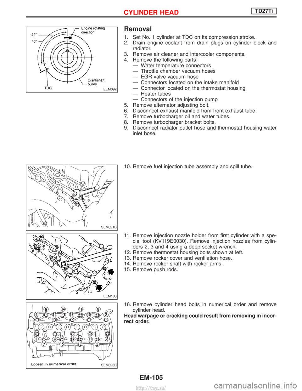
Removal
1. Set No. 1 cylinder at TDC on its compression stroke.
2. Drain engine coolant from drain plugs on cylinder block andradiator.
3. Remove air cleaner and intercooler components.
4. Remove the following parts: Ð Water temperature connectors
Ð Throttle chamber vacuum hoses
Ð EGR valve vacuum hose
Ð Connectors located on the intake manifold
Ð Connector located on the thermostat housing
Ð Heater tubes
Ð Connectors of the injection pump
5. Remove alternator adjusting bolt.
6. Disconnect exhaust manifold from front exhaust tube.
7. Remove turbocharger oil and water tubes.
8. Remove turbocharger bracket bolts.
9. Disconnect radiator outlet hose and thermostat housing water inlet hose.
10. Remove fuel injection tube assembly and spill tube.
11. Remove injection nozzle holder from first cylinder with a spe- cial tool (KV119E0030). Remove injection nozzles from cylin-
ders 2, 3 and 4 using a deep socket wrench.
12. Remove thermostat housing bolts shown at left.
13. Remove rocker cover and ventilation hose.
14. Remove rocker shaft with rocker arms.
15. Remove push rods.
16. Remove cylinder head bolts in numerical order and remove cylinder head.
Head warpage or cracking could result from removing in incor-
rect order.
EEM092
SEM621B
EEM103
SEM623B
CYLINDER HEADTD27Ti
EM-105
http://vnx.su/
Page 210 of 1833
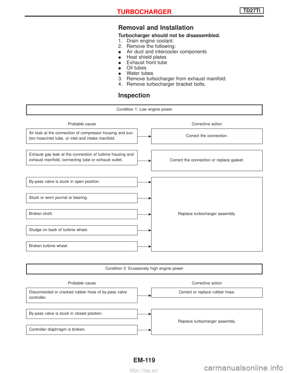
Removal and Installation
Turbocharger should not be disassembled.
1. Drain engine coolant.
2. Remove the following:
IAir duct and intercooler components
I Heat shield plates
I Exhaust front tube
I Oil tubes
I Water tubes
3. Remove turbocharger from exhaust manifold.
4. Remove turbocharger bracket bolts.
Inspection
Condition 1: Low engine power
Probable cause Corrective action
Air leak at the connection of compressor housing and suc-
tion hose/inlet tube, or inlet and intake manifold.
ECorrect the connection.
Exhaust gas leak at the connection of turbine housing and
exhaust manifold, connecting tube or exhaust outlet.
ECorrect the connection or replace gasket.
By-pass valve is stuck in open position.E
Replace turbocharger assembly.
Stuck or worn journal or bearing.E
Broken shaft.E
Sludge on back of turbine wheel.E
Broken turbine wheel.E
Condition 2: Excessively high engine power
Probable cause Corrective action
Disconnected or cracked rubber hose of by-pass valve
controller.
ECorrect or replace rubber hose.
By-pass valve is stuck in closed position.E
Replace turbocharger assembly.
Controller diaphragm is broken.E
TURBOCHARGERTD27Ti
EM-119
http://vnx.su/
Page 249 of 1833
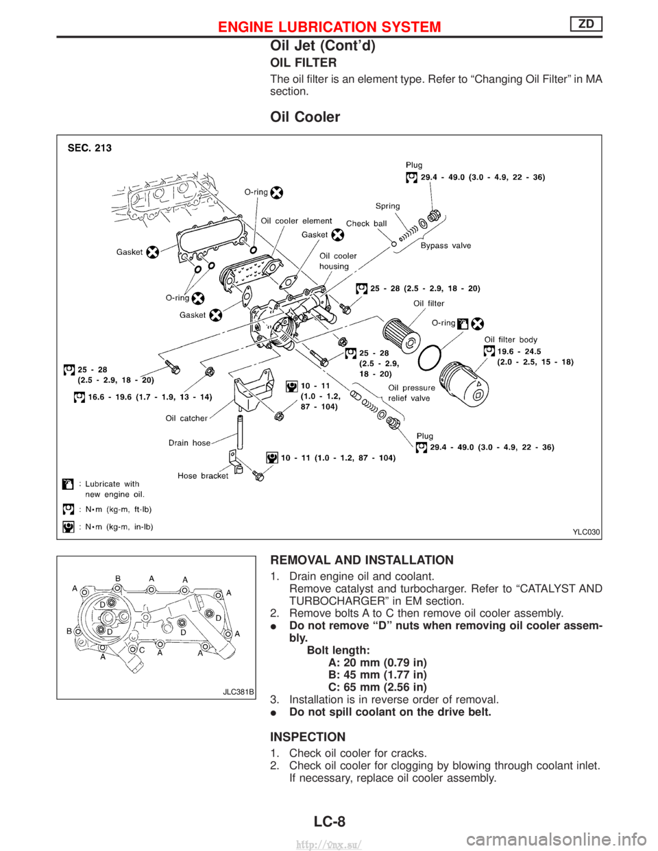
OIL FILTER
The oil filter is an element type. Refer to ªChanging Oil Filterº in MA
section.
Oil Cooler
REMOVAL AND INSTALLATION
1. Drain engine oil and coolant.Remove catalyst and turbocharger. Refer to ªCATALYST AND
TURBOCHARGERº in EM section.
2. Remove bolts A to C then remove oil cooler assembly.
I Do not remove ªDº nuts when removing oil cooler assem-
bly.
Bolt length: A: 20 mm (0.79 in)
B: 45 mm (1.77 in)
C: 65 mm (2.56 in)
3. Installation is in reverse order of removal.
I Do not spill coolant on the drive belt.
INSPECTION
1. Check oil cooler for cracks.
2. Check oil cooler for clogging by blowing through coolant inlet.
If necessary, replace oil cooler assembly.
YLC030
JLC381B
ENGINE LUBRICATION SYSTEMZD
Oil Jet (Cont'd)
LC-8
http://vnx.su/
Page 303 of 1833
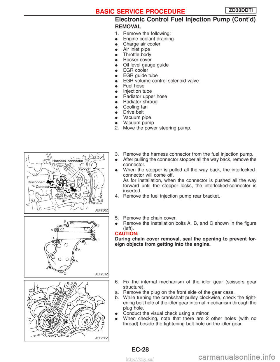
REMOVAL
1. Remove the following:
IEngine coolant draining
I Charge air cooler
I Air inlet pipe
I Throttle body
I Rocker cover
I Oil level gauge guide
I EGR cooler
I EGR guide tube
I EGR volume control solenoid valve
I Fuel hose
I Injection tube
I Radiator upper hose
I Radiator shroud
I Cooling fan
I Drive belt
I Vacuum pipe
I Vacuum pump
2. Move the power steering pump.
3. Remove the harness connector from the fuel injection pump.
I After pulling the connector stopper all the way back, remove the
connector.
I When the stopper is pulled all the way back, the interlocked-
connector will come off.
As for installation, when the connector is pushed all the way
forward until the stopper locks, the interlocked-connector is
inserted.
4. Remove the fuel injection pump rear bracket.
5. Remove the chain cover.
I Remove the installation bolts A, B, and C shown in the figure
(left).
CAUTION:
During chain cover removal, seal the opening to prevent for-
eign objects from getting into the engine.
6. Fix the internal mechanism of the idler gear (scissors gear structure).
a. Remove the plug on the front side of the gear case.
b. While turning the crankshaft pulley clockwise, check the tight- ening bolt hole of the idler gear internal mechanism through the
plug hole.
I Conduct the visual check using a mirror.
I When checking, note that there are 2 other holes (with no
thread) beside the tightening bolt hole on the idler gear.
JEF260Z
JEF261Z
JEF262Z
BASIC SERVICE PROCEDUREZD30DDTi
Electronic Control Fuel Injection Pump (Cont'd)
EC-28
http://vnx.su/