radiator NISSAN TIIDA 2007 Service Owners Manual
[x] Cancel search | Manufacturer: NISSAN, Model Year: 2007, Model line: TIIDA, Model: NISSAN TIIDA 2007Pages: 5883, PDF Size: 78.95 MB
Page 2824 of 5883

TIMING CHAIN
EM-177
< ON-VEHICLE REPAIR >[MR18DE]
C
D
E
F
G
H
I
J
K
L
MA
EM
N
P ORemoval and InstallationINFOID:0000000001337796
CAUTION:
The rotating direction indicated in the text indicates all directions seen from the engine front.
REMOVAL
1. Remove front RH wheel. Refer to WT-6, "Rotation".
2. Remove front fender protector (RH). Refer to EXT-22, "
Removal and Installation".
3. Drain engine oil. Refer to LU-16, "
Changing Engine Oil".
NOTE:
Perform this step when engine is cold.
4. Remove the following parts.
Rocker cover: Refer to EM-173, "
Removal and Installation".
Drive belt: Refer to EM-142, "
Component".
Water pump pulley: Refer to CO-44, "
Component".
Ground cable (between engine bracket (RH) and radiator core support)
5. Support the bottom surface of engine using a transmission jack, and then remove the engine bracket and
insulator (RH). Refer to EM-207
.
6. Set No. 1 cylinder at TDC on its compression stroke with the following procedure:
a. Rotate crankshaft pulley (1) clockwise and align TDC mark (no paint) (B) to timing indicator (A) on front
cover.
b. At the same time, make sure that the cam noses of the No.1 cyl-
inder are located ( ) as shown.
If not, rotate crankshaft pulley one revolution (360 degrees)
and align as shown.
16. Oil pump drive chain 17. Camshaft sprocket (INT) 18. Timing chain tension guide
19. O-ring 20. Chain tensioner (for oil pump)
A. Refer to EM-177
B. Refer to EM-186
C : White paint mark (Not use for service)
PBIC3960E
1 : Camshaft (INT)
2 : Camshaft (EXH)
: Engine front
PBIC3359J
Page 2855 of 5883

EM-208
< REMOVAL AND INSTALLATION >[MR18DE]
ENGINE ASSEMBLY
Always use the support point specified for lifting.
Use either 2-pole lift type or separate type lift as best you can. If board-on type is used for unavoid-
able reasons, support at the rear axle jacking point with a transmission jack or similar tool before
starting work, in preparation for the backward shift of center of gravity.
For supporting points for lifting and jacking point at rear axle, refer to GI-48, "
Garage Jack and
Safety Stand and 2-Pole Lift".
REMOVAL
Remove the engine and the transaxle assembly from the vehicle downward. Separate the engine and the tran-
saxle.
1. Remove engine undercover
2. Drain engine coolant from radiator. Refer to CO-35, "
Changing Engine Coolant".
CAUTION:
Perform this step when the engine is cold.
Do not spill engine coolant on drive belt.
3. Remove front fender protector (RH and LH); Refer to EXT-22, "
Removal and Installation".
4. Remove exhaust front tube; Refer to EX-10, "
Component".
5. Remove drive shafts (LH and RH) from steering knuckle. Refer to FA X - 7 , "
Removal and Installation".
6. Remove transaxle joint bolts which pierce at oil pan (upper) lower rear side. Refer to EM-207, "
Compo-
nent".
7. Remove rear torque rod (1).
8. Remove hood assembly. Refer to DLK-214, "
Removal and Installation".
9. Remove cowl top cover and cowl top extension assembly. Refer to EXT-20, "
Removal and Installation".
10. Release fuel pressure. Refer to EC-1035, "
Inspection".
11. Remove battery and battery tray; Refer to PG-6, "
Removal and Installation".
12. Remove drive belt; Refer to EM-142, "
Component".
13. Remove air duct and air cleaner case assembly; Refer to EM-154
.
14. Remove cooling fan assembly.
15. Remove radiator hose (upper and lower). Refer to CO-40, "
Component".
16. Disconnect all connections of engine harness around the engine mounting insulator (LH), and then tem-
porarily secure the engine harness into the engine side.
CAUTION:
Protect connectors using a resin bag to protect against foreign materials during the operation.
17. Disconnect fuel feed hose at engine side. Refer to EM-162, "
Component".
18. Disconnect heater hoses, and install plugs them to prevent engine coolant from draining. Refer to CO-47,
"Component".
19. Disconnect control cable from transaxle. Refer to TM-674, "
Exploded View".
20. Remove ground cable at transaxle side.
21. Remove ground cable between front cover and vehicle.
22. Remove generator. Refer to CHG-29, "
Removal and Installation".
23. Remove A/C compressor with piping connected from the engine. Temporarily secure it on the vehicle side
with a rope to avoid putting load on it. Refer to HA-32, "
Removal and Installation of Compressor -
MR18DE".
LBIA0460E
Page 2918 of 5883

CHARGE AIR COOLER
EM-271
< ON-VEHICLE REPAIR >[K9K]
C
D
E
F
G
H
I
J
K
L
MA
EM
N
P O
4. Remove air inlet hoses.
5. Release the clamp (A) securing the charge air cooler (1) to radi-
ator (2) and pull to release charge air cooler from the radiator
lower core support (3).
6. Remove charge air cooler (1) from underbody as shown.
CAUTION:
Avoid interference between the charge air cooler and con-
denser.
When removing charge air cooler, close opening on turbo
charger and throttle with shop cloth or other suitable
material.
INSTALLATION
Installation is in the reverse order of removal.
Apply a neutral detergent (fluid) to the joint between hoses and pipes (oil is not permissible).
Pay attention to identification mark and direction.
InspectionINFOID:0000000001381473
INSPECTION AFTER REMOVAL
1. Check that the charge air cooler is not full of oil. In that case, clean it with cleaning agent and then let it
dry.
2. Check air passages of charge air cooler core and fins for clogging, leaks or deformation. Clean or replace
charge air cooler in necessary.
Be careful not to deform core fins.
MBIB9031E
MBIB9020E
Page 2919 of 5883

EM-272
< ON-VEHICLE REPAIR >[K9K]
EGR SYSTEM
EGR SYSTEM
Exploded ViewINFOID:0000000001381474
Removal and InstallationINFOID:0000000001381475
REMOVAL
1. Remove battery ground cable.
2. Remove engine undercover using power tool.
3. Drain engine coolant. Refer to CO-58, "
Draining".
4. Remove lower radiator hose. Refer to CO-62, "
Exploded View".
5. Remove cowl top cover and cowl top extension assembly. Refer to EXT-20, "
Removal and Installation".
6. Remove air cleaner and air duct assembly. Refer to EM-269, "
Removal and Installation".
7. Remove charge air cooler inlet tubes at EGR assembly. Refer to EM-270, "
Exploded View".
8. Disconnect EGR volume control valve and electronic throttle control actuator connectors.
9. Disconnect heater hoses from EGR cooler cover.
10. Remove EGR cooler cover.
11. Remove front engine slinger.
12. Remove air inlet tube.
13. Remove RH fender protector. Refer to EXT-22, "
Removal and Installation".
1. Air inlet tube 2. Engine slinger 3. O-ring
4. Bracket 5. EGR tube 6. Gasket
7. EGR cooler 8. Gasket 9. EGR volume control valve
10. Gasket 11. EGR volume control valve housing 12. Clamp
13. EGR tube 14. Gasket 15. Gasket
16. Electronic throttle control actuator 17. O-ring 18. EGR cooler cover
A. To intake manifold B. To exhaust manifold
E1BIA0025GB
Page 2950 of 5883

ENGINE ASSEMBLY
EM-303
< REMOVAL AND INSTALLATION >[K9K]
C
D
E
F
G
H
I
J
K
L
MA
EM
N
P O
Remove engine and transaxle assembly from vehicle down ward. Separate engine and transaxle.
Preparation
Remove the following parts.
Battery ground cable.
Engine undercover.
LH and RH front wheels. Refer to WT-6, "
Rotation".
LH and RH fender protectors. Refer to EXT-22, "
Removal and Installation".
Engine Room
1. Drain engine coolant. Refer to CO-58, "Draining".
CAUTION:
Perform when engine is cold.
2. Remove lower radiator hose. Refer to CO-62, "
Exploded View".
3. Drain transaxle fluid. Refer to TM-672, "
Draining".
4. Disconnect clutch tube at clutch housing and drain clutch fluid.
NOTE:
Cover clutch tube ends to prevent contamination.
5. Remove hood. Refer to DLK-214, "
Removal and Installation".
6. Remove cowl top cover and cowl top extension assembly. Refer to EXT-20, "
Removal and Installation".
7. Remove battery and battery trap. Refer to PG-6, "
Removal and Installation".
8. Disconnect engine room harness from the engine side and position aside.
9. Remove the air duct (inlet). Refer to EM-269, "
Exploded View".
10. Remove engine cover.
11. Remove blow-by hose.
12. Remove air cleaner case and air duct (suction). Refer to EM-269, "
Removal and Installation".
13. Remove reservoir tank and hoses. Refer to CO-62, "
Exploded View".
14. Remove charge air cooler hoses and tubes. Refer to EM-270, "
Exploded View".
15. Remove vacuum hose. Refer to EM-280, "
Removal and Installation".
16. Disconnect fuel feed and return hoses, and plug it to prevent fuel from draining.
17. Remove radiator upper hose. Refer to CO-62, "
Exploded View".
18. Disconnect heater hoses.
19. Disconnect transaxle side harness.
20. Disconnect breather hose transaxle side.
21. Disconnect shift cable and select cable. Refer to TM-674, "
Exploded View".
22. Remove cooling fan. Refer to CO-64, "
Removal and Installation".
23. Remove radiator. Refer to CO-62, "
Exploded View".
24. Disconnect all the body-side vacuum hoses and air hoses at engine side.
Vehicle Underbody
1. Remove drive shaft assembly RH and LH. Refer to Removal and Installation.
2. Remove exhaust front tube. Refer to EX-14, "
Component".
3. Remove drive belt. Refer to EM-263, "
Removal and Installation".
4. Remove A/C compressor and position aside.
NOTE:
Secure it to body with a rope to avoid putting load on A/C lines.
5. Remove lower torque rod. Refer to EM-302, "
Exploded View".
Removal
Page 3111 of 5883
SQUEAK AND RATTLE TROUBLE DIAGNOSIS
EXT-7
< ON-VEHICLE MAINTENANCE >
C
D
E
F
G
H
I
J
L
MA
B
EXT
N
O
P
4. A loose license plate or bracket
Most of these incidents can be repaired by adjusting, securing or insulating the item(s) or component(s) caus-
ing the noise.
SUNROOF/HEADLINING
Noises in the sunroof/headlining area can often be traced to one of the following:
1. Sunroof lid, rail, linkage or seals making a rattle or light knocking noise
2. Sun visor shaft shaking in the holder
3. Front or rear windshield touching headliner and squeaking
Again, pressing on the components to stop the noise while duplicating the conditions can isolate most of these
incidents. Repairs usually consist of insulating with felt cloth tape.
OVERHEAD CONSOLE (FRONT AND REAR)
Overhead console noises are often caused by the console panel clips not being engaged correctly. Most of
these incidents are repaired by pushing up on the console at the clip locations until the clips engage.
In addition look for:
1. Loose harness or harness connectors.
2. Front console map/reading lamp lens loose.
3. Loose screws at console attachment points.
SEATS
When isolating seat noise it's important to note the position the seat is in and the load placed on the seat when
the noise is present. These conditions should be duplicated when verifying and isolating the cause of the
noise.
Cause of seat noise include:
1. Headrest rods and holder
2. A squeak between the seat pad cushion and frame
3. The rear seatback lock and bracket
These noises can be isolated by moving or pressing on the suspected components while duplicating the con-
ditions under which the noise occurs. Most of these incidents can be repaired by repositioning the component
or applying urethane tape to the contact area.
UNDERHOOD
Some interior noise may be caused by components under the hood or on the engine wall. The noise is then
transmitted into the passenger compartment.
Causes of transmitted underhood noise include:
1. Any component installed on the engine wall
2. Components that pass through the engine wall
3. Engine wall mounts and connectors
4. Loose radiator pins
5. Hood bumpers out of adjustment
6. Hood striker out of adjustment
These noises can be difficult to isolate since they cannot be reached from the interior of the vehicle. The best
method is to secure, move or insulate one component at a time and test drive the vehicle. Also, engine RPM
or load can be changed to isolate the noise. Repairs can usually be made by moving, adjusting, securing, or
insulating the component causing the noise.
Page 3123 of 5883

FRONT GRILLE
EXT-19
< ON-VEHICLE REPAIR >
C
D
E
F
G
H
I
J
L
MA
B
EXT
N
O
P
FRONT GRILLE
Removal and InstallationINFOID:0000000001568929
REMOVAL
1. Open hood assembly.
2. Remove the clips, then remove upper radiator cover.
3. Remove the upper clips and release the lower pawls, then pull outward to remove the front grille.
INSTALLATION
Installation is in the reverse order of removal.
LIIA2564E
1. Upper radiator cover 2. Front grille 3. Front bumper fascia
4. Clip C205 Pawl
Page 3238 of 5883
GI-44
< PRECAUTION >
PRECAUTIONS
General Precaution
INFOID:0000000001606118
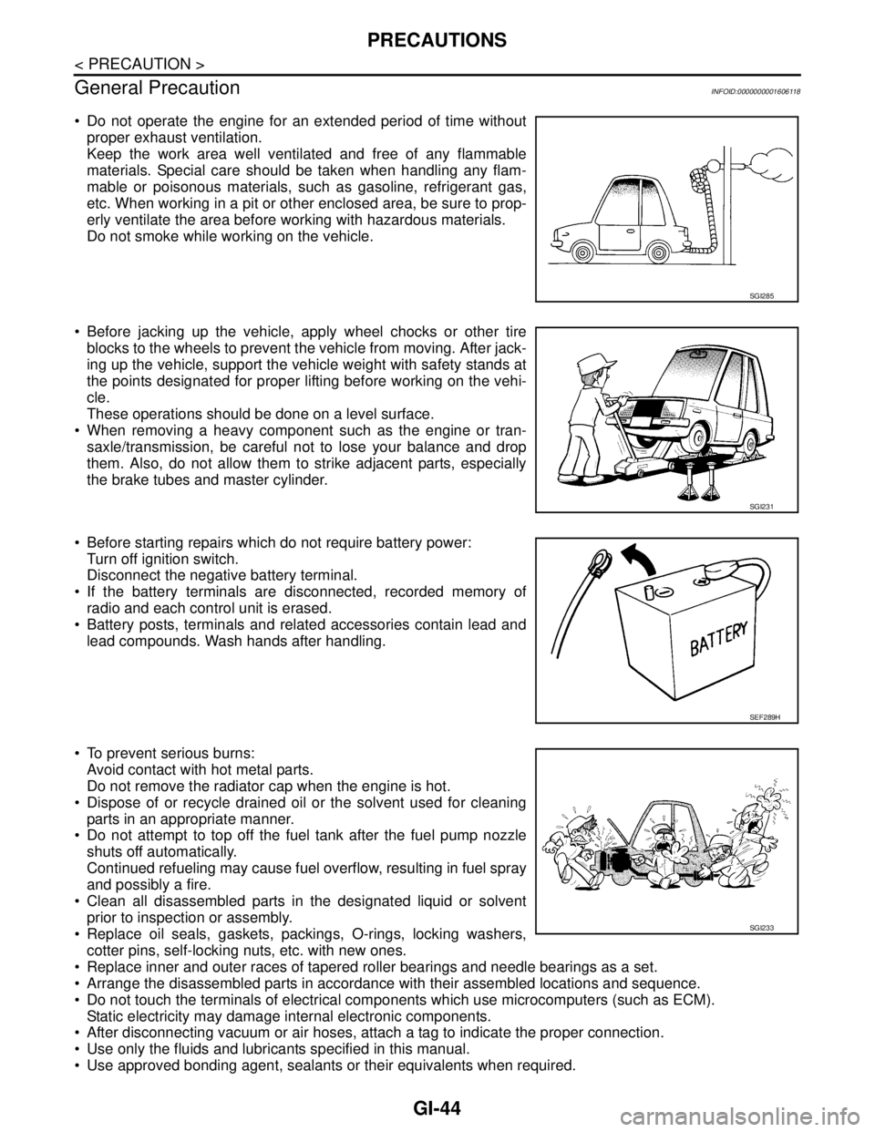
Do not operate the engine for an extended period of time without
proper exhaust ventilation.
Keep the work area well ventilated and free of any flammable
materials. Special care should be taken when handling any flam-
mable or poisonous materials, such as gasoline, refrigerant gas,
etc. When working in a pit or other enclosed area, be sure to prop-
erly ventilate the area before working with hazardous materials.
Do not smoke while working on the vehicle.
Before jacking up the vehicle, apply wheel chocks or other tire
blocks to the wheels to prevent the vehicle from moving. After jack-
ing up the vehicle, support the vehicle weight with safety stands at
the points designated for proper lifting before working on the vehi-
cle.
These operations should be done on a level surface.
When removing a heavy component such as the engine or tran-
saxle/transmission, be careful not to lose your balance and drop
them. Also, do not allow them to strike adjacent parts, especially
the brake tubes and master cylinder.
Before starting repairs which do not require battery power:
Turn off ignition switch.
Disconnect the negative battery terminal.
If the battery terminals are disconnected, recorded memory of
radio and each control unit is erased.
Battery posts, terminals and related accessories contain lead and
lead compounds. Wash hands after handling.
To prevent serious burns:
Avoid contact with hot metal parts.
Do not remove the radiator cap when the engine is hot.
Dispose of or recycle drained oil or the solvent used for cleaning
parts in an appropriate manner.
Do not attempt to top off the fuel tank after the fuel pump nozzle
shuts off automatically.
Continued refueling may cause fuel overflow, resulting in fuel spray
and possibly a fire.
Clean all disassembled parts in the designated liquid or solvent
prior to inspection or assembly.
Replace oil seals, gaskets, packings, O-rings, locking washers,
cotter pins, self-locking nuts, etc. with new ones.
Replace inner and outer races of tapered roller bearings and needle bearings as a set.
Arrange the disassembled parts in accordance with their assembled locations and sequence.
Do not touch the terminals of electrical components which use microcomputers (such as ECM).
Static electricity may damage internal electronic components.
After disconnecting vacuum or air hoses, attach a tag to indicate the proper connection.
Use only the fluids and lubricants specified in this manual.
Use approved bonding agent, sealants or their equivalents when required.
SGI285
SGI231
SEF289H
SGI233
Page 3264 of 5883
SQUEAK AND RATTLE TROUBLE DIAGNOSES
GW-5
< SYMPTOM DIAGNOSIS >
C
D
E
F
G
H
I
J
L
MA
B
GW
N
O
P
2. Trunk lid striker out of adjustment
3. The trunk lid torsion bars knocking together
4. A loose license plate or bracket
Most of these incidents can be repaired by adjusting, securing or insulating the item(s) or component(s) caus-
ing the noise.
SUNROOF/HEADLINING
Noises in the sunroof/headlining area can often be traced to one of the following:
1. Sunroof lid, rail, linkage or seals making a rattle or light knocking noise
2. Sun visor shaft shaking in the holder
3. Front or rear windshield touching headliner and squeaking
Again, pressing on the components to stop the noise while duplicating the conditions can isolate most of these
incidents. Repairs usually consist of insulating with felt cloth tape.
OVERHEAD CONSOLE (FRONT AND REAR)
Overhead console noises are often caused by the console panel clips not being engaged correctly. Most of
these incidents are repaired by pushing up on the console at the clip locations until the clips engage.
In addition look for:
1. Loose harness or harness connectors.
2. Front console map/reading lamp lense loose.
3. Loose screws at console attachment points.
SEATS
When isolating seat noise it's important to note the position the seat is in and the load placed on the seat when
the noise is present. These conditions should be duplicated when verifying and isolating the cause of the
noise.
Cause of seat noise include:
1. Headrest rods and holder
2. A squeak between the seat pad cushion and frame
3. The rear seatback lock and bracket
These noises can be isolated by moving or pressing on the suspected components while duplicating the con-
ditions under which the noise occurs. Most of these incidents can be repaired by repositioning the component
or applying urethane tape to the contact area.
UNDERHOOD
Some interior noise may be caused by components under the hood or on the engine wall. The noise is then
transmitted into the passenger compartment.
Causes of transmitted underhood noise include:
1. Any component mounted to the engine wall
2. Components that pass through the engine wall
3. Engine wall mounts and connectors
4. Loose radiator mounting pins
5. Hood bumpers out of adjustment
6. Hood striker out of adjustment
These noises can be difficult to isolate since they cannot be reached from the interior of the vehicle. The best
method is to secure, move or insulate one component at a time and test drive the vehicle. Also, engine RPM
or load can be changed to isolate the noise. Repairs can usually be made by moving, adjusting, securing, or
insulating the component causing the noise.
Page 3327 of 5883
CONDENSER
HA-45
< ON-VEHICLE REPAIR >
C
D
E
F
G
H
J
K
L
MA
B
HA
N
O
P
CONDENSER
Removal and Installation of Condenser - MR18DE, HR16DEINFOID:0000000001527646
REMOVAL
1. Use the recovery/recycling equipment to evacuate the refrigerant. Refer to HA-21, "HFC-134a (R-134a)
Service Procedure".
2. Remove the three upper headlamp bolts to reposition the headlamps out of the way
3. Remove the radiator core support upper.
4. Disconnect the high-pressure flexible hose and high-pressure pipe from condenser.
CAUTION:
Cap or wrap the joint of the pipe with suitable material such as vinyl tape to avoid the entry of air.
5. Disconnect refrigerant pressure sensor connector.
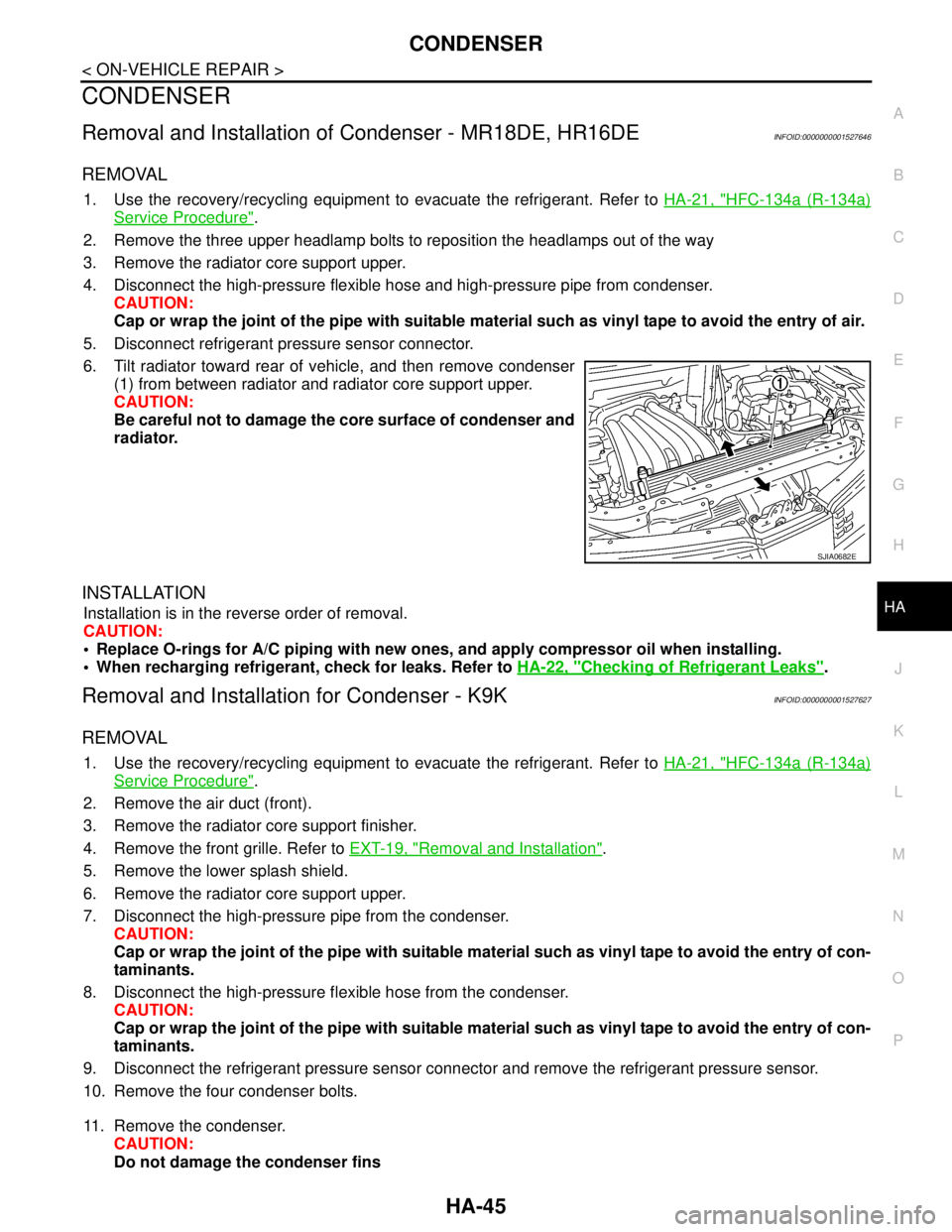
6. Tilt radiator toward rear of vehicle, and then remove condenser
(1) from between radiator and radiator core support upper.
CAUTION:
Be careful not to damage the core surface of condenser and
radiator.
INSTALLATION
Installation is in the reverse order of removal.
CAUTION:
Replace O-rings for A/C piping with new ones, and apply compressor oil when installing.
When recharging refrigerant, check for leaks. Refer to HA-22, "
Checking of Refrigerant Leaks".
Removal and Installation for Condenser - K9KINFOID:0000000001527627
REMOVAL
1. Use the recovery/recycling equipment to evacuate the refrigerant. Refer to HA-21, "HFC-134a (R-134a)
Service Procedure".
2. Remove the air duct (front).
3. Remove the radiator core support finisher.
4. Remove the front grille. Refer to EXT-19, "
Removal and Installation".
5. Remove the lower splash shield.
6. Remove the radiator core support upper.
7. Disconnect the high-pressure pipe from the condenser.
CAUTION:
Cap or wrap the joint of the pipe with suitable material such as vinyl tape to avoid the entry of con-
taminants.
8. Disconnect the high-pressure flexible hose from the condenser.
CAUTION:
Cap or wrap the joint of the pipe with suitable material such as vinyl tape to avoid the entry of con-
taminants.
9. Disconnect the refrigerant pressure sensor connector and remove the refrigerant pressure sensor.
10. Remove the four condenser bolts.
11. Remove the condenser.
CAUTION:
Do not damage the condenser fins
SJIA0682E