warning NISSAN TIIDA 2007 Service Repair Manual
[x] Cancel search | Manufacturer: NISSAN, Model Year: 2007, Model line: TIIDA, Model: NISSAN TIIDA 2007Pages: 5883, PDF Size: 78.95 MB
Page 1 of 5883

MODEL C11 SERIES
2007 NISSAN EUROPE S.A.S.
All rights reserved. No part of this Electronic Service Manual may be reproduced or stored in a retrieval system, or transmitted in any form,
or by any means, electronic, mechanical, photocopying, recording or otherwise, without the prior written permission of Nissan Europe
S.A.S., Paris, France.
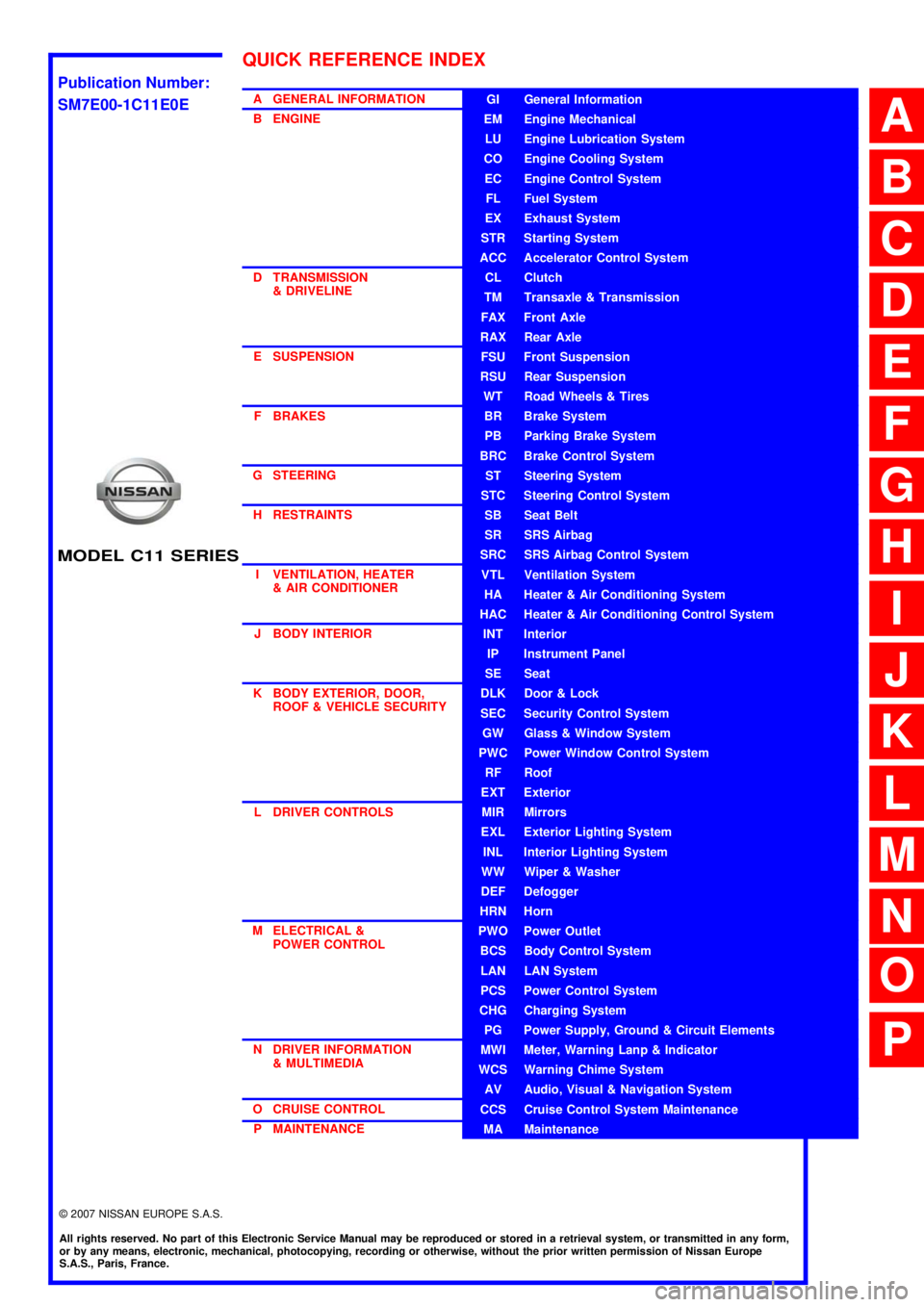
A GENERAL INFORMATION
B ENGINE
D TRANSMISSION& DRIVELINE
E SUSPENSION F BRAKES
G STEERING H RESTRAINTS
I VENTILATION, HEATER & AIR CONDITIONER
J BODY INTERIOR
K BODY EXTERIOR, DOOR, ROOF & VEHICLE SECURITY
L DRIVER CONTROLS
M ELECTRICAL & POWER CONTROL
N DRIVER INFORMATION & MULTIMEDIA
O CRUISE CONTROL P MAINTENANCEGI General Information
EM Engine Mechanical
LU Engine Lubrication System
CO Engine Cooling System
EC Engine Control System
FL Fuel System
EX Exhaust System
STR Starting System
ACC Accelerator Control System
CL Clutch
TM Transaxle & Transmission
FAX Front Axle
RAX Rear Axle
FSU Front Suspension
RSU Rear Suspension
WT Road Wheels & Tires
BR Brake System
PB Parking Brake System
BRC Brake Control System
ST Steering System
STC Steering Control System
SB Seat Belt
SR SRS Airbag
SRC SRS Airbag Control System
VTL Ventilation System
HA Heater & Air Conditioning System
HAC Heater & Air Conditioning Control System
INT Interior
IP Instrument Panel
SE Seat
DLK Door & Lock
SEC Security Control System
GW Glass & Window System
PWC Power Window Control System
RF Roof
EXT Exterior
MIR Mirrors
EXL Exterior Lighting System
INL Interior Lighting System
WW Wiper & Washer
DEF Defogger
HRN Horn
PWO Power Outlet
BCS Body Control System
LAN LAN System
PCS Power Control System
CHG Charging System
PG Power Supply, Ground & Circuit Elements
MWI Meter, Warning Lanp & Indicator
WCS Warning Chime System
AV Audio, Visual & Navigation System
CCS Cruise Control System Maintenance
MA Maintenance
QUICK REFERENCE INDEX
A
B
C
D
E
F
G
H
I
J
K
L
M
N
O
P
M
Publication Number:
SM7E00-1C11E0E
Page 4 of 5883

ACC-2
< PRECAUTION >
PRECAUTIONS
PRECAUTION
PRECAUTIONS
Precaution for Supplemental Restraint System (SRS) "AIR BAG" and "SEAT BELT
PRE-TENSIONER"
INFOID:0000000001724596
The Supplemental Restraint System such as “AIR BAG” and “SEAT BELT PRE-TENSIONER”, used along
with a front seat belt, helps to reduce the risk or severity of injury to the driver and front passenger for certain
types of collision. Information necessary to service the system safely is included in the SR and SB section of
this Service Manual.
WARNING:
• To avoid rendering the SRS inoperative, which could increase the risk of personal injury or death in
the event of a collision which would result in air bag inflation, all maintenance must be performed by
an authorized NISSAN/INFINITI dealer.
Improper maintenance, including incorrect removal and installation of the SRS, can lead to personal
injury caused by unintentional activation of the system. For removal of Spiral Cable and Air Bag
Module, see the SR section.
Do not use electrical test equipment on any circuit related to the SRS unless instructed to in this
Service Manual. SRS wiring harnesses can be identified by yellow and/or orange harnesses or har-
ness connectors.
Page 26 of 5883
![NISSAN TIIDA 2007 Service Repair Manual AV
PRECAUTIONS
AV-21
< PRECAUTION >[AUDIO WITHOUT NAVIGATION]
C
D
E
F
G
H
I
J
K
L
MB A
O
P
PRECAUTION
PRECAUTIONS
Precaution for Supplemental Restraint System (SRS) "AIR BAG" and "SEAT BELT
PRE-TENSI NISSAN TIIDA 2007 Service Repair Manual AV
PRECAUTIONS
AV-21
< PRECAUTION >[AUDIO WITHOUT NAVIGATION]
C
D
E
F
G
H
I
J
K
L
MB A
O
P
PRECAUTION
PRECAUTIONS
Precaution for Supplemental Restraint System (SRS) "AIR BAG" and "SEAT BELT
PRE-TENSI](/img/5/57395/w960_57395-25.png)
AV
PRECAUTIONS
AV-21
< PRECAUTION >[AUDIO WITHOUT NAVIGATION]
C
D
E
F
G
H
I
J
K
L
MB A
O
P
PRECAUTION
PRECAUTIONS
Precaution for Supplemental Restraint System (SRS) "AIR BAG" and "SEAT BELT
PRE-TENSIONER"
INFOID:0000000001731028
The Supplemental Restraint System such as “AIR BAG” and “SEAT BELT PRE-TENSIONER”, used along
with a front seat belt, helps to reduce the risk or severity of injury to the driver and front passenger for certain
types of collision. Information necessary to service the system safely is included in the “SRS AIRBAG” and
“SEAT BELT” of this Service Manual.
WARNING:
• To avoid rendering the SRS inoperative, which could increase the risk of personal injury or death in
the event of a collision which would result in air bag inflation, all maintenance must be performed by
an authorized NISSAN/INFINITI dealer.
Improper maintenance, including incorrect removal and installation of the SRS, can lead to personal
injury caused by unintentional activation of the system. For removal of Spiral Cable and Air Bag
Module, see the “SRS AIRBAG”.
Do not use electrical test equipment on any circuit related to the SRS unless instructed to in this
Service Manual. SRS wiring harnesses can be identified by yellow and/or orange harnesses or har-
ness connectors.
Page 113 of 5883
![NISSAN TIIDA 2007 Service Repair Manual AV-108
< SYMPTOM DIAGNOSIS >[AUDIO WITH NAVIGATION]
MULTI AV SYSTEM SYMPTOMS
SYMPTOM DIAGNOSIS
MULTI AV SYSTEM SYMPTOMS
Symptom TableINFOID:0000000001728767
RELATED TO NAVIGATION
NOTE:
Combined part o NISSAN TIIDA 2007 Service Repair Manual AV-108
< SYMPTOM DIAGNOSIS >[AUDIO WITH NAVIGATION]
MULTI AV SYSTEM SYMPTOMS
SYMPTOM DIAGNOSIS
MULTI AV SYSTEM SYMPTOMS
Symptom TableINFOID:0000000001728767
RELATED TO NAVIGATION
NOTE:
Combined part o](/img/5/57395/w960_57395-112.png)
AV-108
< SYMPTOM DIAGNOSIS >[AUDIO WITH NAVIGATION]
MULTI AV SYSTEM SYMPTOMS
SYMPTOM DIAGNOSIS
MULTI AV SYSTEM SYMPTOMS
Symptom TableINFOID:0000000001728767
RELATED TO NAVIGATION
NOTE:
Combined part of AV switch and audio unit.
RELATED TO REAR VIEW MONITOR
Symptoms Check items Possible malfunction location/Action to take
AV switch cannot be operated.
(All switches cannot be operated.)“MULTI AV” is displayed on “SELECT
SYSTEM” screen of CONSULT-III.Perform the self-diagnosis using CONSULT-III.
(AV- 4 8 , "
CONSULT - III Function (MULTI AV)")
“MULTI AV” is not displayed on “SE-
LECT SYSTEM” screen of CON-
SULT-III. NAVI control unit power supply and ground circuit
(AV- 8 0 , "
NAVI CONTROL UNIT : Diagnosis Proce-
dure")
Perform CAN diagnosis when “Please wait” is indi-
cated on the screen for approximately 120 seconds
after ignition switch ON.
AV switch cannot be operated.
(Only specified switch cannot be
operated.)CONSULT-III self-diagnosis detects
a malfunction.Perform the self-diagnosis using CONSULT-III.
(AV- 4 8 , "
CONSULT - III Function (MULTI AV)")
CONSULT-III self-diagnosis does not
detect a malfunction.Audio unit (XX-XX, "*****"
)
Map screen is not displayed.
(RGB image other than map is
normal.)–Perform the self-diagnosis using CONSULT-III.
(AV- 4 8 , "
CONSULT - III Function (MULTI AV)")
Fuel economy information display
is malfunctioning.–NAVI control unit power supply and ground circuit (Igni-
tion signal) (AV- 8 0 , "
NAVI CONTROL UNIT : Diagnosis
Procedure")
Voice guidance is not heard. – Voice guidance signal circuit
Traffic information (RDS-TMC) is
not received.Radio broadcasts are received. Audio unit (XX-XX, "*****"
)
Radio broadcasts are not received. Radio antenna (XX-XX, "*****"
)
Antenna feeder (XX-XX, "*****"
)
Symptoms Check items Possible malfunction location/Action to take
Warning message under the dis-
play is not displayed at rear view
monitor image.– Horizontal synchronizing (HP) signal circuit (AV- 8 7 ,
"Diagnosis Procedure")
Vertical synchronizing (VP) signal circuit (AV- 8 8 , "
Di-
agnosis Procedure")
RGB area (YS) signal circuit (AV- 8 6 , "
Diagnosis Pro-
cedure")
Camera image is not shown.
(Only warning message under the
display is displayed.)“REAR VIEW CAMERA” is displayed
on “SELECT SYSTEM” screen of
CONSULT-III. Camera image signal circuit (positive circuit)
(Between camera control unit and display unit)
(XX-XX, "*****"
)
Camera ON signal circuit (XX-XX, "*****"
)
Camera image signal circuit
(Between rear view camera and camera control unit)
(XX-XX, "*****"
)
“REAR VIEW CAMERA” is not dis-
played on “SELECT SYSTEM”
screen of CONSULT-III.Camera control unit power supply and ground circuit
(XX-XX, "*****"
)
Camera image is rolling. –Camera image signal circuit (negative circuit)
(Between camera control unit and display unit)
(XX-XX, "*****"
)
Page 124 of 5883
![NISSAN TIIDA 2007 Service Repair Manual AV
PRECAUTIONS
AV-119
< PRECAUTION >[AUDIO WITH NAVIGATION]
C
D
E
F
G
H
I
J
K
L
MB A
O
P
PRECAUTION
PRECAUTIONS
Precaution for Supplemental Restraint System (SRS) "AIR BAG" and "SEAT BELT
PRE-TENSION NISSAN TIIDA 2007 Service Repair Manual AV
PRECAUTIONS
AV-119
< PRECAUTION >[AUDIO WITH NAVIGATION]
C
D
E
F
G
H
I
J
K
L
MB A
O
P
PRECAUTION
PRECAUTIONS
Precaution for Supplemental Restraint System (SRS) "AIR BAG" and "SEAT BELT
PRE-TENSION](/img/5/57395/w960_57395-123.png)
AV
PRECAUTIONS
AV-119
< PRECAUTION >[AUDIO WITH NAVIGATION]
C
D
E
F
G
H
I
J
K
L
MB A
O
P
PRECAUTION
PRECAUTIONS
Precaution for Supplemental Restraint System (SRS) "AIR BAG" and "SEAT BELT
PRE-TENSIONER"
INFOID:0000000001731029
The Supplemental Restraint System such as “AIR BAG” and “SEAT BELT PRE-TENSIONER”, used along
with a front seat belt, helps to reduce the risk or severity of injury to the driver and front passenger for certain
types of collision. Information necessary to service the system safely is included in the “SRS AIRBAG” and
“SEAT BELT” of this Service Manual.
WARNING:
To avoid rendering the SRS inoperative, which could increase the risk of personal injury or death in
the event of a collision which would result in air bag inflation, all maintenance must be performed by
an authorized NISSAN/INFINITI dealer.
Improper maintenance, including incorrect removal and installation of the SRS, can lead to personal
injury caused by unintentional activation of the system. For removal of Spiral Cable and Air Bag
Module, see the “SRS AIRBAG”.
Do not use electrical test equipment on any circuit related to the SRS unless instructed to in this
Service Manual. SRS wiring harnesses can be identified by yellow and/or orange harnesses or har-
ness connectors.
Page 139 of 5883

BCS-4
< BASIC INSPECTION >
INSPECTION AND ADJUSTMENT
When replacing BCM, you must perform WRITE CONFIGURATION with CONSULT-III.
Complete the procedure of WRITE CONFIGURATION in order.
If you set incorrect WRITE CONFIGURATION, incidents will occur.
Configuration is different for each vehicle model. Confirm configuration of each vehicle model.
CONFIGURATION : Special Repair RequirementINFOID:0000000001451452
1. WRITING VEHICLE SPECIFICATION
Perform “WRITE CONFIGURATION” with CONSULT-III.
When writing saved data>>GO TO 2
When writing manually>>GO TO 3
2. PERFORM “WRITE CONFIGURATION - CONFIG FILE”
Perform “WRITE CONFIGURATION - Config file” with CONSULT-III.
>> WORK END
3. PERFORM “WRITE CONFIGURATION - MANUAL SELECTION”
For “WRITE CONFIGURATION - Manual selection”, using the following flow chart, identify the correct model
and configuration list.
Confirm and/or change setting value for each item according to the configuration list.
Depending on CONSULT-III software version being used, some or all of the write configuration items shown in
the following configuration lists may be displayed. If an item does not display on the CONSULT-III “WRITE
CONFIGURATION - Manual selection” screen, then it is an auto setting item and it cannot be manually set or
changed.
Gasoline engine models (RHD)
Gasoline engine models (LHD)
MANUAL SETTING ITEM
Items Setting value
HANDLE RHD
PTC HEATER WITHOUT
AUTO LIGHT WITH⇔WITHOUT
KEYLESS ENTRY WITH⇔WITHOUT
DTRL WITHOUT
THEFT ALARM WITH⇔WITHOUT
AUTO SETTING ITEM
RAIN SENSOR WITH or WITHOUT
H/L WSR SWTRG FR WSR SW
H/L_BULB H4 HALOGEN or DEFAULT
FR FOG LAMP WITH or WITHOUT
DONGLE WITH or WITHOUT
SUPER LOCK WITH
I-KEY WITH or WITHOUT
DOOR/L SPEED WITH
H/L BAT SAVER WITH
KEY WARNING MODE1
R LAMP LOGIC MODE2
Page 140 of 5883

BCS
INSPECTION AND ADJUSTMENT
BCS-5
< BASIC INSPECTION >
C
D
E
F
G
H
I
J
K
L B A
O
P N
Diesel engine models (RHD)
Diesel engine models (LHD)
MANUAL SETTING ITEM
Items Setting value
HANDLE LHD
PTC HEATER WITHOUT
AUTO LIGHT WITH⇔WITHOUT
KEYLESS ENTRY WITH⇔WITHOUT
DTRL WITH⇔WITHOUT
THEFT ALARM WITHOUT
AUTO SETTING ITEM
RAIN SENSOR WITH or WITHOUT
H/L WSR SWTRG FR WSR SW
H/L_BULB H4 HALOGEN or DEFAULT
FR FOG LAMP WITH or WITHOUT
DONGLE WITH or WITHOUT
SUPER LOCK WITHOUT
I-KEY WITH or WITHOUT
DOOR/L SPEED WITH
H/L BAT SAVER WITH
KEY WARNING MODE1
R LAMP LOGIC MODE2
MANUAL SETTING ITEM
Items Setting value
HANDLE RHD
PTC HEATER WITHOUT
AUTO LIGHT WITH⇔WITHOUT
KEYLESS ENTRY WITH⇔WITHOUT
DTRL WITHOUT
THEFT ALARM WITH⇔WITHOUT
AUTO SETTING ITEM
RAIN SENSOR WITH or WITHOUT
H/L WSR SWTRG FR WSR SW
H/L_BULB H4 HALOGEN or DEFAULT
FR FOG LAMP WITH or WITHOUT
DONGLE WITH or WITHOUT
SUPER LOCK WITH
I-KEY WITH or WITHOUT
DOOR/L SPEED WITH
H/L BAT SAVER WITH
KEY WARNING MODE1
R LAMP LOGIC MODE2
Page 141 of 5883

BCS-6
< BASIC INSPECTION >
INSPECTION AND ADJUSTMENT
>> WORK END
MANUAL SETTING ITEM
Items Setting value
HANDLE LHD
PTC HEATER 2 PTC
AUTO LIGHT WITH⇔WITHOUT
KEYLESS ENTRY WITH⇔WITHOUT
DTRL WITH⇔WITHOUT
THEFT ALARM WITHOUT
AUTO SETTING ITEM
RAIN SENSOR WITH or WITHOUT
H/L WSR SWTRG FR WSR SW
H/L_BULB H4 HALOGEN or DEFAULT
FR FOG LAMP WITH or WITHOUT
DONGLE WITH or WITHOUT
SUPER LOCK WITHOUT
I-KEY WITH or WITHOUT
DOOR/L SPEED WITH
H/L BAT SAVER WITH
KEY WARNING MODE1
R LAMP LOGIC MODE2
Page 142 of 5883

BCS
BODY CONTROL SYSTEM
BCS-7
< FUNCTION DIAGNOSIS >
C
D
E
F
G
H
I
J
K
L B A
O
P N
FUNCTION DIAGNOSIS
BODY CONTROL SYSTEM
System DescriptionINFOID:0000000001451453
OUTLINE
BCM (Body Control Module) controls the various electrical components. It inputs the information required to
the control from CAN communication and the signal received from each switch and sensor.
BCM has combination switch reading function for reading the operation status of combination switches (light,
turn signal, wiper and washer) in addition to a function for controlling the operation of various electrical com-
ponents. It also has the signal transmission function as the passed point of signal and the power consump-
tion control function that reduces the power consumption with the ignition switch OFF.
BCM is equipped with the diagnosis function that performs the diagnosis with CONSULT-III and various set-
tings.
BCM control function list
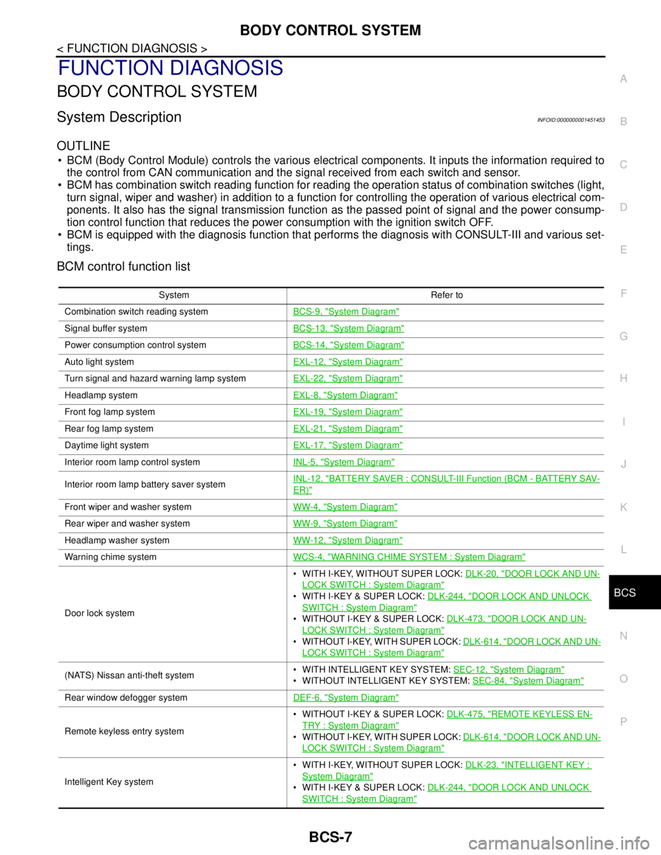
System Refer to
Combination switch reading systemBCS-9, "
System Diagram"
Signal buffer systemBCS-13, "System Diagram"
Power consumption control systemBCS-14, "System Diagram"
Auto light systemEXL-12, "System Diagram"
Turn signal and hazard warning lamp systemEXL-22, "System Diagram"
Headlamp systemEXL-8, "System Diagram"
Front fog lamp systemEXL-19, "System Diagram"
Rear fog lamp systemEXL-21, "System Diagram"
Daytime light systemEXL-17, "System Diagram"
Interior room lamp control systemINL-5, "System Diagram"
Interior room lamp battery saver systemINL-12, "BATTERY SAVER : CONSULT-III Function (BCM - BATTERY SAV-
ER)"
Front wiper and washer systemWW-4, "System Diagram"
Rear wiper and washer systemWW-9, "System Diagram"
Headlamp washer systemWW-12, "System Diagram"
Warning chime systemWCS-4, "WARNING CHIME SYSTEM : System Diagram"
Door lock system WITH I-KEY, WITHOUT SUPER LOCK: DLK-20, "
DOOR LOCK AND UN-
LOCK SWITCH : System Diagram"
WITH I-KEY & SUPER LOCK: DLK-244, "DOOR LOCK AND UNLOCK
SWITCH : System Diagram"
WITHOUT I-KEY & SUPER LOCK: DLK-473, "DOOR LOCK AND UN-
LOCK SWITCH : System Diagram"
WITHOUT I-KEY, WITH SUPER LOCK: DLK-614, "DOOR LOCK AND UN-
LOCK SWITCH : System Diagram"
(NATS) Nissan anti-theft system WITH INTELLIGENT KEY SYSTEM: SEC-12, "System Diagram"
WITHOUT INTELLIGENT KEY SYSTEM: SEC-84, "System Diagram"
Rear window defogger systemDEF-6, "System Diagram"
Remote keyless entry system WITHOUT I-KEY & SUPER LOCK: DLK-475, "
REMOTE KEYLESS EN-
TRY : System Diagram"
WITHOUT I-KEY, WITH SUPER LOCK: DLK-614, "DOOR LOCK AND UN-
LOCK SWITCH : System Diagram"
Intelligent Key system WITH I-KEY, WITHOUT SUPER LOCK: DLK-23, "
INTELLIGENT KEY :
System Diagram"
WITH I-KEY & SUPER LOCK: DLK-244, "DOOR LOCK AND UNLOCK
SWITCH : System Diagram"
Page 150 of 5883

BCS
POWER CONSUMPTION CONTROL SYSTEM
BCS-15
< FUNCTION DIAGNOSIS >
C
D
E
F
G
H
I
J
K
L B A
O
P N
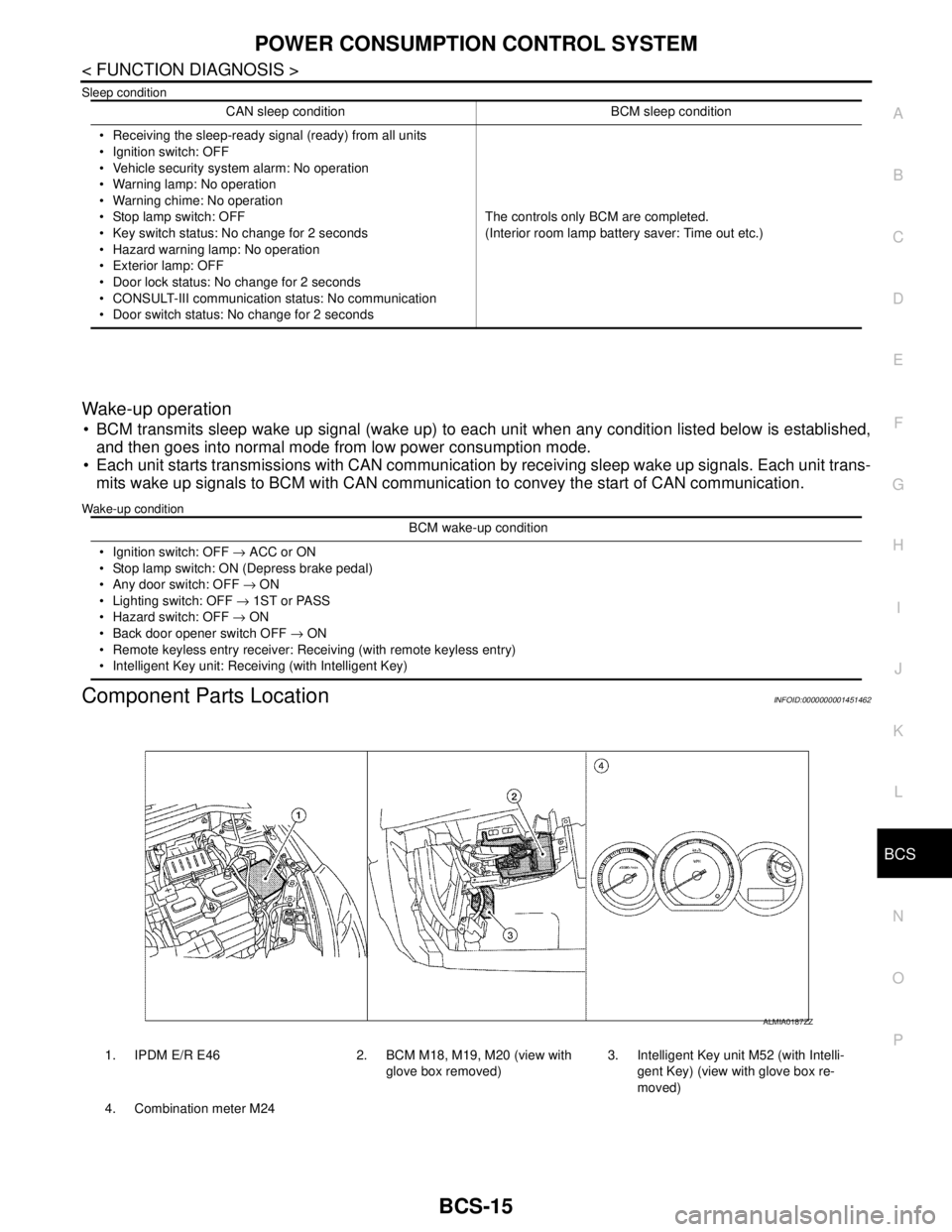
Sleep condition
Wake-up operation
BCM transmits sleep wake up signal (wake up) to each unit when any condition listed below is established,
and then goes into normal mode from low power consumption mode.
Each unit starts transmissions with CAN communication by receiving sleep wake up signals. Each unit trans-
mits wake up signals to BCM with CAN communication to convey the start of CAN communication.
Wake-up condition
Component Parts LocationINFOID:0000000001451462
CAN sleep condition BCM sleep condition
Receiving the sleep-ready signal (ready) from all units
Ignition switch: OFF
Vehicle security system alarm: No operation
Warning lamp: No operation
Warning chime: No operation
Stop lamp switch: OFF
Key switch status: No change for 2 seconds
Hazard warning lamp: No operation
Exterior lamp: OFF
Door lock status: No change for 2 seconds
CONSULT-III communication status: No communication
Door switch status: No change for 2 secondsThe controls only BCM are completed.
(Interior room lamp battery saver: Time out etc.)
BCM wake-up condition
Ignition switch: OFF → ACC or ON
Stop lamp switch: ON (Depress brake pedal)
Any door switch: OFF → ON
Lighting switch: OFF → 1ST or PASS
Hazard switch: OFF → ON
Back door opener switch OFF → ON
Remote keyless entry receiver: Receiving (with remote keyless entry)
Intelligent Key unit: Receiving (with Intelligent Key)
1. IPDM E/R E46 2. BCM M18, M19, M20 (view with
glove box removed)3. Intelligent Key unit M52 (with Intelli-
gent Key) (view with glove box re-
moved)
4. Combination meter M24
ALMIA0187ZZ